EP0594255A1 - A device for manufacturing a mould for a disc-shaped registration carrier - Google Patents
A device for manufacturing a mould for a disc-shaped registration carrier Download PDFInfo
- Publication number
- EP0594255A1 EP0594255A1 EP93202917A EP93202917A EP0594255A1 EP 0594255 A1 EP0594255 A1 EP 0594255A1 EP 93202917 A EP93202917 A EP 93202917A EP 93202917 A EP93202917 A EP 93202917A EP 0594255 A1 EP0594255 A1 EP 0594255A1
- Authority
- EP
- European Patent Office
- Prior art keywords
- substrate
- station
- arm
- photoresist layer
- pivotable
- Prior art date
- Legal status (The legal status is an assumption and is not a legal conclusion. Google has not performed a legal analysis and makes no representation as to the accuracy of the status listed.)
- Granted
Links
Images


Classifications
-
- G—PHYSICS
- G11—INFORMATION STORAGE
- G11B—INFORMATION STORAGE BASED ON RELATIVE MOVEMENT BETWEEN RECORD CARRIER AND TRANSDUCER
- G11B7/00—Recording or reproducing by optical means, e.g. recording using a thermal beam of optical radiation by modifying optical properties or the physical structure, reproducing using an optical beam at lower power by sensing optical properties; Record carriers therefor
- G11B7/24—Record carriers characterised by shape, structure or physical properties, or by the selection of the material
- G11B7/26—Apparatus or processes specially adapted for the manufacture of record carriers
- G11B7/261—Preparing a master, e.g. exposing photoresist, electroforming
-
- B—PERFORMING OPERATIONS; TRANSPORTING
- B29—WORKING OF PLASTICS; WORKING OF SUBSTANCES IN A PLASTIC STATE IN GENERAL
- B29D—PRODUCING PARTICULAR ARTICLES FROM PLASTICS OR FROM SUBSTANCES IN A PLASTIC STATE
- B29D17/00—Producing carriers of records containing fine grooves or impressions, e.g. disc records for needle playback, cylinder records; Producing record discs from master stencils
- B29D17/005—Producing optically read record carriers, e.g. optical discs
-
- G—PHYSICS
- G11—INFORMATION STORAGE
- G11B—INFORMATION STORAGE BASED ON RELATIVE MOVEMENT BETWEEN RECORD CARRIER AND TRANSDUCER
- G11B7/00—Recording or reproducing by optical means, e.g. recording using a thermal beam of optical radiation by modifying optical properties or the physical structure, reproducing using an optical beam at lower power by sensing optical properties; Record carriers therefor
- G11B7/24—Record carriers characterised by shape, structure or physical properties, or by the selection of the material
- G11B7/26—Apparatus or processes specially adapted for the manufacture of record carriers
- G11B7/263—Preparing and using a stamper, e.g. pressing or injection molding substrates
-
- Y—GENERAL TAGGING OF NEW TECHNOLOGICAL DEVELOPMENTS; GENERAL TAGGING OF CROSS-SECTIONAL TECHNOLOGIES SPANNING OVER SEVERAL SECTIONS OF THE IPC; TECHNICAL SUBJECTS COVERED BY FORMER USPC CROSS-REFERENCE ART COLLECTIONS [XRACs] AND DIGESTS
- Y10—TECHNICAL SUBJECTS COVERED BY FORMER USPC
- Y10S—TECHNICAL SUBJECTS COVERED BY FORMER USPC CROSS-REFERENCE ART COLLECTIONS [XRACs] AND DIGESTS
- Y10S414/00—Material or article handling
- Y10S414/135—Associated with semiconductor wafer handling
- Y10S414/141—Associated with semiconductor wafer handling includes means for gripping wafer
-
- Y—GENERAL TAGGING OF NEW TECHNOLOGICAL DEVELOPMENTS; GENERAL TAGGING OF CROSS-SECTIONAL TECHNOLOGIES SPANNING OVER SEVERAL SECTIONS OF THE IPC; TECHNICAL SUBJECTS COVERED BY FORMER USPC CROSS-REFERENCE ART COLLECTIONS [XRACs] AND DIGESTS
- Y10—TECHNICAL SUBJECTS COVERED BY FORMER USPC
- Y10S—TECHNICAL SUBJECTS COVERED BY FORMER USPC CROSS-REFERENCE ART COLLECTIONS [XRACs] AND DIGESTS
- Y10S430/00—Radiation imagery chemistry: process, composition, or product thereof
- Y10S430/146—Laser beam
Definitions
- the invention relates to a device for manufacturing a mould for a disc-shaped registration carrier, said device being provided with a station for applying a photosensitive layer, such as a photoresist layer, to a substrate, with a station for exposing said photosensitive layer in accordance with the registration data to be stored, with a station for developing the photosensitive layer and metallizing the side of the substrate carrying the developed photoresist layer, with a station for applying a metal coating and with a station for applying a protective lacquer coating.
- a photosensitive layer such as a photoresist layer
- registration carriers is understood to mean sound and/or picture carriers and/or data carriers and the like, for example so-called compact discs, as well as carriers which can be processed at a later stage for storing sound, pictures or other data to be registered thereon.
- a method for manufacturing such a mould is for example described in Dutch Patent Application No. 8802211. Said publication does not provide any indication with regard to the construction of a device to be used for carrying out such a method, however.
- Dutch Patent Application No. 8702157 describes a device for carrying out a certain treatment of such registration carriers, whereby the device is provided with a rotary table for supporting a registration carrier, which rotary table and its driving mechanism are movable between several stations. Not only does this lead to a complicated construction of the device, but a further drawback is that the processing of a registration carrier in the first station cannot start before the processing in the last station has been completed and the rotary table has been returned to the first station. It will be apparent that an economical mass production cannot be realized with such a device.
- the object of the invention is to obtain a device of the above kind, which can have an efficient and compact construction and wherein the successive operations can take place in succession and without the operator having to take action.
- the substrates may be transported in the desired manner by means of the transport mechanism, between the substrate receiving means provided in the various stations, whilst desired operations may be carried out, independently of each other, on the substrate in each of said stations.
- Figure 1 is a diagrammatic front view of the device according to the invention.
- Figure 2 is a diagrammatic plan view of the various stations of the device according to the invention.
- Figure 3 is a cross-sectional view of the device shown in Figures 1 and 2.
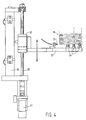
- Figure 4 is an elevational view of a device for removing a substrate from a stack of substrates and for transferring said substrate to the transport mechanism.
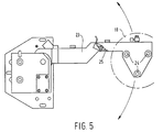
- Figure 5 is a plan view of Figure 4.
- Figure 6 is a plan view of the mechanism for cleaning and applying a first coating and a photoresist layer.
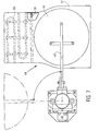
- Figure 7 is a plan view of parts of a drying station.
- Figure 8 is a side view of Figure 7.
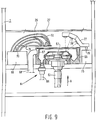
- Figure 9 is a view, partly in section and partly in elevation, of the developing and metallizing station.
- Figure 10 is an elevational view of the means for placing contact rings on a substrate.
- Figure 11 is a plan view of Figure 10.
- Figure 12 is an elevational view of the means for placing a clamping ring on a substrate.
- Figure 13 is a plan view of Figure 12.
- Figure 14 shows a mechanism for carrying out the immersing step in a bath (likewise shown) containing electrolytic fluid.
- Figure 15 is a larger-scale view of a detail of the construction shown in Figure 14.
- Figure 16 is an elevational view of a part of a station, where the mould obtained can be subjected to a finishing operation.
- Figure 17 is a plan view of Figure 16.
- the device shown in Figures 1 - 3 comprises a housing 1, which is closed during normal operation, in which several units 2 - 7 are accommodated.
- the design of said units 2 - 7 is such that it is possible to remove such a unit as a whole, so as to be replaced as desired by a unit carrying out (a) corresponding operation(s) or (an)other operation(s).
- a girder 8 is provided, which extends in the longitudinal direction of the device and which forms part of a transport mechanism.
- a slide 9 is reciprocatingly movable along said girder by means of a driving mechanism (not shown), as indicated by means of the arrow A.
- the slide 9 supports a girder 10 extending perpendicularly to the girder 8, along which a further slide 9' is reciprocatingly movable in the direction according to the arrow B.
- the slide 10 functions to support two transport means 11 and 12, which are provided with radially movable hook-shaped fingers 13.
- the transport means 11 and 12 are reciprocatingly movable in vertical direction by driving means (not shown).
- a transport means can be placed on a substrate, and when the fingers 13 are moved inwards again the hook-shaped ends of the fingers will engage under the substrate, so that the substrate can thus be lifted by a respective transport means and be moved through the housing by means of the above-described transport mechanism.
- the housing may be subdivided into three compartments 14 - 16, one being located above the other.
- the uppermost compartment 14 actually accommodates the transport mechanism.
- the compartment 15 located thereunder which may be subdivided near the units 2 - 7 in the manner shown in Figures 1 and 2, accommodates the various means yet to be described for processing the registration carrier. At least some of these units will be provided with a rotary table as diagrammatically indicated in Figure 3.
- the lowermost compartment 16, likewise subdivided in correlation with the units 2 - 7, will accommodate auxiliary means, such as electronic equipment, liquid-containing vessels and the like.
- auxiliary means such as electronic equipment, liquid-containing vessels and the like.
- said auxiliary means are disposed on slides, so that they can be moved into and out of the housing transversely to the longitudinal direction of the housing in order to carry out maintenance work and the like.
- the unit 3 is provided with an opening, through which a holder supporting a number of substrates arranged one on top of the other, generally glass discs, may be disposed in the device.
- a mechanism which is shown in more detail in Figures 4 and 5, is disposed near said introduction opening, said mechanism functioning to remove a substrate from the stack and deliver said substrate to the transportmechanism.
- a number of substrates 18, for example glass discs, are stacked one on top of the other within the housing.
- the mechanism shown in Figures 4 and 5 comprises a support 19 secured to the frame of the device, in which a vertical lead screw 20 is rotatably journalled.
- the lead screw 20 can be rotated by means of a driving motor 21 connected to said lead screw.
- the lead screw 20 is passed through a nut means 22, which is locked against rotation about the central axis of the lead screw 20 in a manner not shown.
- a nut means 22 Connected to said nut means 22 is one end of an arm 23, which is rotatable about the central axis of the lead screw 20 with respect to the nut means 22, by driving means not shown, and which is capable of vertical reciprocating movement along with the lead screw.
- Three suction pads 24 facing upwards are secured to the free end of the arm 23.
- the arm 23 When a stack of substrates 18 has been placed in the device, the arm 23 may be moved to a position under the stack by means of a suitable control mechanism, then be pivoted under the stack and be moved upwards until the suction pads 24 abut against the bottom side of the lowermost substrate 18. This position is detected by means of a sensor 25 mounted on the arm. In the suction pads 24 a sub-atmospheric pressure can be generated by means not shown, after which the lowermost substrate 18 can be pivoted away from its position under the stack of substrates remaining behind to a position beside the holder with substrates. In this position the substrate 18 can be taken over from the arm 23 by one of the transport means 11 or 12.
- the registration carriers will be wet during certain stages of the process.
- the one transport means may be used for transporting dry substrates and the other transport means may be used for transporting wet substrates, as a result of which undesirable contamination of the substrate and the device can be avoided.
- a substrate 18 usually formed by a glass disc
- said substrate may be moved upwards into the space 14 through a hole 27 provided in the wall 26 closing the compartment 15 at its upper side and be transported to the unit 4, in order to be moved downwards there through a hole 27 provided in the wall 26 to a station 28 for cleaning and applying a first coating and a so-called lacquer coating or photoresist layer.
- this station 28 comprises a rotary table 29, which is disposed within a cup-shaped means, whose construction at least substantially corresponds with the cup-shaped yet to be described in more detail with reference to Figure 9.
- a rinsing liquid deionized water in this case, will be spread over the upper surface of the substrate by means of the supply pipe 33 in order to rinse the substrate.
- rinsing liquid While rinsing liquid is being supplied the upper surface of the substrate is also brushed clean by means of the brush 36, which has been pivoted to a position above the substrate. After cleaning the brush may be pivoted back to the position shown in Figure 6, in which the brush is located above a pan 37 (diagrammatically shown), to which a drain pipe 38 is connected for draining moisture dripping from the brush.
- a first coating may be applied via pipe 33. After a first coating has been applied the material for forming the eventual lacquer coating or so-called photoresist layer is applied by means of the supply pipe 34 and spread over the substrate surface.
- suction pipe 39 for exhausting vapours is connected to the cup-shaped pan 30.
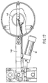
- said substrate After the lacquer coating or photoresist layer has thus been applied to the substrate, said substrate will be moved by means of the transport mechanism to the station 40 for drying the lacquer coating.
- An air line with a horizontal pipe part 41 shown in station 40 in the Figures is provided for the drying of the lacquer.
- a rotary table 42 is at least partially disposed within the interior of the pipe part 41, through a hole provided in the bottom wall of the pipe part 41.
- Said rotary table is provided with three suction pads 43, in which a sub-atmospheric pressure can be generated for fixing a substrate 18 on the rotary table in question.
- the rotary table can be rotated by means of a driving motor 44 coupled to the rotary table.
- the substrate 18 can be placed on the rotary table by means of the transport mechanism, through an opening provided in the upper wall of the pipe part 41, which opening can be closed by means of a cover 45.
- the cover 45 is secured to one end of a supporting arm 45'.
- the supporting arm 45' is secured to a vertical shaft 46, which can be rotated about its central axis by means of a rotation motor 47.
- the shaft 46 is furthermore supported by a supporting mechanism 48, which can be moved upwards and downwards by means of a setting cylinder 49.
- a supporting mechanism 48 which can be moved upwards and downwards by means of a setting cylinder 49.
- the air passage may be closed by moving the cover in opposite direction. Then an air flow may be generated in the air passage by means of a fan (not shown).
- Heating coils 50 extending perpendicularly to the longitudinal direction of the air passage are provided for the heating of the air in the air passage, said heating coils in Figure 7 being shown in a position turned through 90° with respect to their actual position.
- a diaphragm 51 which slightly narrows the air passage, is provided between the rotary table and the heating coils in the air passage, in order to effect an air flow as even as possible over the substrate supported on the rotary table.
- cooler air for cooling the substrate is passed through the air line for some time.
- the substrate which is now provided with a photoresist layer, may be supplied to a station 52 for recording the desired information on the registration carrier.
- This station 52 comprises a rotary table 53, on which the substrate 18 provided with a lacquer coating or photoresist layer can be placed by means of the transport mechanism.
- the station 52 conventionally comprises a laser device 54, as well as an optical apparatus 55, by means of which the light beam is emitted to lenses 57 supported by a carrier 56.
- the carrier 56 is secured to a shaft 58, which can be moved lengthwise by means of a driving mechanism 59 in order to move the carrier over guide rails 60, in such a manner that the carrier moves over the substrate 18 supported by the rotary table 53.
- a driving mechanism 59 in order to move the carrier over guide rails 60, in such a manner that the carrier moves over the substrate 18 supported by the rotary table 53.
- the substrate 18 is moved to a station 61 by means of the above-described transport mechanism.
- the station 61 comprises a rotary table 62 for receiving a substrate.
- the rotary table 62 can be rotated about a vertical axis by means of a motor 63.
- the rotary table 62 is disposed in a cup-shaped means 65, to the bottom side of which a drain pipe 66 is connected.
- a circular recess 67 is provided in the cup-shaped means, the inner wall of said recess being located slightly lower than the outer wall, as will be apparent from Figure 9.
- a pipe 68 for exhausting vapours is connected to said recess 67.
- a rotary shaft 70 which is rotatable about a vertical axis of rotation by means of a driving mechanism 69, is provided near the rotary table, to which rotary shaft the end of an arm 71 is secured.
- the end of the arm 71 functions to support a plurality of pipes 72 for supplying various liquids when the end of the arm 71 in question supporting the pipes is located above the cup-shaped means in the manner indicated in Figure 9.
- the arm 71 can be pivoted to a position in which the free end of the arm supporting the pipes is located above a pan 74 ( Figure 2), so that any liquid dripping from the pipes or rinsing liquid used for flushing the pipes can be drained via the pan 74.
- a further vertical shaft 76 which is rotatable by a driving means 75, supports an arm 77, to which three lenses 78 are secured.
- the lenses 78 function to pick up laser light beamed in the direction according to the arrow B, which can move through the substrate processed in the above-described manner and which is subsequently picked up by the lenses 78.
- the light picked up by the lenses is influenced by the configuration which the photoresist layer obtains during the processing step, and thus it is made possible to check whether or not the desired processing is carried out in the desired manner.
- the remaining photoresist layer and/or the upper surface of the substrate 18 is metallized by supplying suitable liquids, generally provided with a nickel coating, so that a product is obtained which in principle corresponds with the product depicted in Figure 2 of the aforesaid Dutch Patent Application No. 8802211.
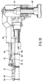
- the substrate 18 and the photoresist layer applied thereto have thus been treated in the station 61 and after the arms 77 and 71 have been pivoted to a position beside the cup-shaped means, the substrate is transported to a subsequent station 80 by means of the transport mechanism, and that on a supporting plate 81 ( Figure 15) secured to the upper end of a supporting arm 82, which, when the substrate is being placed, occupies the vertical position shown in Figure 14. From this position the supporting arm 82 is pivotable about a horizontal pivot axis 84 to the position illustrated in dotted lines in Figure 14 by means of a setting cylinder (not shown), which is coupled to the arm 82 by means of a connecting rod 83.
- a setting cylinder not shown
- the substrate 18 will thereby come to lie on the upper ends of a few compression springs 85 mounted within the supporting plate 81.
- a thin metal contact ring 86 in particular made of stainless steel or nickel, must be placed on the substrate, the dimensions of said ring being such that the ring covers a narrow outer edge of the substrate and slightly projects beyond the substrate at the outer side.
- This mechanism comprises a supporting means 87, which is vertically movable by means of a setting cylinder 88.
- Said supporting means 87 supports a vertical shaft 89, to which one end of an arm 90 is secured.
- the shaft 89 with the arm 90 secured thereto can be pivoted about the vertical axis of the shaft 89 by means of a setting cylinder 91 secured to the supporting means, the piston rod 91' of said setting cylinder being coupled to the shaft 89.
- the free end of the arm 90 is formed by a plate 92.
- a disc 93 is supported on the plate 92, which disc is rotatable about an axis 94 with respect to the plate 92.
- the plate 93 is coupled to a piston rod 95 of a setting cylinder 96 secured to the arm 90 with a view to rotating the plate 93.
- Three slotted holes 97 are provided in the plate 93, in such a manner that the distance between the axis 94 and the respective slotted holes from one end of each of said slotted holes to the other end of each of said slotted holes gradually increases.
- Vertical pins 98 are located within said slotted holes 97, said pins being connected to the ends of rods 99, which extend in radial direction with respect to the axis 94.
- the rods 99 are accommodated in guide blocks 99' secured to the plate 92 so as to be movable in longitudinal direction.
- Downwardly extending arms 100 are secured to the ends of rods 99, and fingers 101 are secured to the ends of said arms 100.
- a plurality of rings 86 one lying above the other in a rack or the like, will be disposed near the station 80, for example in the position 86 diagrammatically indicated in Figure 10.
- the uppermost ring from the stack may now be picked up by means of the mechanism described with reference to Figures 10 and 11, by first moving the fingers outwards by means of the arms 99, and furthermore moving the fingers to a position in which they are located under the uppermost ring of the stack, by pivoting and vertically moving the arm 90 in a suitable manner, after which the fingers may be moved towards each other again, so that the fingers 101 will come to lie under the uppermost ring of the stack. Then the uppermost ring may be moved to a position above the substrate supported by the' supporting plate 81, by suitably moving the arm 90 in vertical direction and pivoting said arm, so as to place the ring on said substrate in this manner.
- the mechanism shown in Figures 12 and 13 is disposed in station 80 with a view to providing a clamping ring 102.
- the clamping ring 102 has a more or less L-shaped section, the configuration being such that in the mounted position of the clamping ring 102 one leg of the clamping ring 102, with a sealing ring 103 provided therein, will come to lie on the ring 86, whilst the other leg will more or less extend along the outer circumference of the supporting plate 81.
- Three radially extending pins 104 are provided in the outer circumference of the supporting plate 81 in regularly spaced-apart relationship, in such a manner that said pins project beyond the outer circumference of the supporting plate 81, and are able to cooperate with L-shaped slotted holes 105 provided in the clamping ring 102, the short leg of said slotted holes being open at a point located at the inner side and bottom side of the clamping ring, and the long leg extending in circumferential direction.
- the mechanism shown in Figure 12 and 13 for providing or removing the clamping ring 102 comprises a supporting means 106, which is vertically movable by means of a setting cylinder 107.
- the supporting means supports a vertical shaft 108, to which the free end of an arm 109 is secured.
- the shaft 108, together with the arm 109, is pivotable about the central axis of the shaft 108 by means of a setting cylinder 110 secured to the supporting means 106, a piston rod of said setting cylinder being coupled to the shaft 108.
- the free end of the arm 109 supports a disc 113 by means of a vertical shaft 112, said disc being rotatable about the central axis of the vertical shaft 112 by means of a setting cylinder 114 secured to the arm 109.
- a further plate 115 is secured to the bottom side of the plate 113 by means of bolts 116. Said bolts 116 are passed through slotted holes 117, in order to enable a correct adjustment of the two plates 113 and 115 with respect to each other.
- a few pins 117 extending under the plate 115 are secured to the plate 115 at regular intervals. Heads 118 are secured to the bottom ends of said pins, which heads are accommodated in curved slotted holes 119 provided in the interior of the clamping ring 102, said slotted holes at one end being provided with an enlarged hole 120, which is open at the upper side of the clamping ring, through which a head 118 may be introduced into the slotted hole 119 or be removed therefrom, as the case may be, upon suitable vertical movement of the arm 109 with the parts supported by the arm and rotation of the plates 113 and 115 about the shaft 112.
- the clamping ring 102 By pivoting of the arm 109 the clamping ring 102 can be moved to a position above the supporting plate 81 shown in Figure 15 and subsequently be moved downwards, in such a manner that the pins 104 will move towards the inside through the vertically extending parts of the L-shaped slotted holes 105 and the clamping ring 102 will be supported on the ring 86. Then the clamping ring may be rotated by rotating the interconnected plates 113 and 115 by means of the setting cylinder 114, whereby the clamping ring is taken along by the plates 113 and 115 via the bolts 117. At the end of the rotation the pins 104 will be located near the closed ends of the horizontally extending parts of the slotted holes 105.
- the plates 113 and 115 may be pivoted to a position in which the heads 118 will come to lie near the recesses 120, so that the plates 113 and 115 can then be moved upwards with the pins 117 whilst leaving behind the clamping ring 102 on the supporting plate 81.
- the substrate 18 thus clamped down and the stainless steel contact ring 86 clamped down thereon may be pivoted into a vessel 125 containing electrolytic fluid.
- a housing 126 is disposed within said vessel, which housing is provided with an opening 127 at one side, opposite which the supporting plate 81 with the substrate 18 clamped down thereon is disposed in the manner illustrated in dotted lines in Figure 14.
- a plate 129 may be moved in front of the opening 127 within the housing 126, said plate being provided with a passage 130, which is adapted to the substrate surface to be metallized. Since the plate 129 is readily exchangeable with another plate having another passage, the size of the passage may readily be adjusted according to what is required.
- a receiving means 131 is placed within the vessel, in which receiving means a large number of metal balls, generally nickel balls 132, will be located.
- receiving means a large number of metal balls generally nickel balls 132
- the distance between the receiving means 132 containing the nickel balls and the substrate to be treated may be kept comparatively small, in the order of ⁇ 35 mm, which has a positive effect on the quick and even coating of the substrate.
- a number of liquid passages 133 are provided over a circumferential angle of ⁇ 50° in the wall of the housing 126 bounding the opening 127. Through these openings fresh electrolyte may be supplied, in such a manner that said fresh electrolyte approximately flows in a direction parallel to the surface of the substrate 18, as is indicated by means of the arrow C.
- the nickel deposit on the substrate and the metal contact ring placed thereon will for example act as a cathode thereby, and the nickel balls will form the anode, as is usual in processes like this.
- the supporting plate 81 will be pivoted back again, whereby the supporting plate with the substrate and the coating will be rinsed with hot deionized water. Then the supporting plate is pivoted back to the position shown in Figure 14, after which the clamping ring 102 can be removed by reversing the above-described steps for providing the clamping ring 102. Then the substrate with the coating provided thereon, which is now integral with the ring 86 placed on the substrate, may be removed by means of the transport mechanism and be placed on a pivotable arm 140, which is disposed in a further station 141.
- the construction of the pivotable arm 140 at least substantially corresponds with the above-described arm 23, and the substrates may be placed in a rack 142 provided in the station 141 by means of said arm 140, which is pivotable about a vertical axis and which is vertically movable as well.
- the substrates processed in this manner can be removed from the device through an access door (not shown), so that the substrate can be removed in the usual manner, for example by hand, from the so-called male mould formed on the substrate in the above-described manner, which will look as shown in Figure 4 of the above-mentioned Dutch Patent Application No. 8802211.
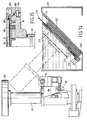
- said male mould may be placed on a rotary table 145 present in the station 141 with its embossed surface turned upwards, after which a light source 146 (diagrammatically indicated), which is secured to an arm 147, which is pivotable about a vertical axis, may be moved over the plate so as to develop the residual lacquer or photoresist remaining behind on the male mould that has been formed. Then a spraying mechanism 149 secured to the end of an arm 148 ( Figures 16, 17) may be pivoted above the male mould supported on the rotary table. The arm 148 can be moved upwards and downwards, in a similar manner as described above, by means of a setting cylinder 150, and also be pivoted about a vertical pivot axis by means of a horizontal setting cylinder 151.
- rinsing liquid may be sprayed on the male mould 152 supported on the rotary table 145 (not shown in Figure 16), so as to rinse the male mould.
- a lacquer coating may be provided on the male mould 152 via the spraying device 149.
- the arm 148 is moved downwards, so that a receiving ring 153 coupled to a shell 153' secured to the arm 148 and surrounding the spraying mechanism will come to rest on the upwardly tapering circumferential surface of the cup-shaped means 154 accommodating the rotary table 145.
- a bottom ring 155 of the receiving ring is designed to slope upwards from its outer circumference towards the inside, as a result of which a space 156 for catching any residual lacquer is formed between the outer wall of the receiving ring 153 and the bottom ring 155.
- the receiving ring 153 is coupled to the shell 153' by means of pins 157 and suitable L-shaped slotted holes, which form some kind of bayonet catch, so as to be readily detachable, so that the receiving ring 153 can readily be removed and cleaned when a certain amount of lacquer has been collected in the ring.
- the male mould thus completed may be discharged from the device so as to be stored and/or be supplied to further processing machines.
- the housing 1 will be closed and clean air can be supplied to the substrate processing stations through ducts 158 bounded by the housing and a grid 159.
- the station 52 near one end of the housing 1, since the equipment disposed in said station, such as the laser device and the optics, comprises sensitive components, which require regular maintenance.
- the housing 1 may also be curved, for example.
Landscapes
- Engineering & Computer Science (AREA)
- Manufacturing & Machinery (AREA)
- Mechanical Engineering (AREA)
- Manufacturing Optical Record Carriers (AREA)
- Container, Conveyance, Adherence, Positioning, Of Wafer (AREA)
- Moulds For Moulding Plastics Or The Like (AREA)
- Coating Apparatus (AREA)
- Perforating, Stamping-Out Or Severing By Means Other Than Cutting (AREA)
Abstract
Description
- The invention relates to a device for manufacturing a mould for a disc-shaped registration carrier, said device being provided with a station for applying a photosensitive layer, such as a photoresist layer, to a substrate, with a station for exposing said photosensitive layer in accordance with the registration data to be stored, with a station for developing the photosensitive layer and metallizing the side of the substrate carrying the developed photoresist layer, with a station for applying a metal coating and with a station for applying a protective lacquer coating.
- The term registration carriers is understood to mean sound and/or picture carriers and/or data carriers and the like, for example so-called compact discs, as well as carriers which can be processed at a later stage for storing sound, pictures or other data to be registered thereon.
- A method for manufacturing such a mould is for example described in Dutch Patent Application No. 8802211. Said publication does not provide any indication with regard to the construction of a device to be used for carrying out such a method, however.
- Dutch Patent Application No. 8702157 describes a device for carrying out a certain treatment of such registration carriers, whereby the device is provided with a rotary table for supporting a registration carrier, which rotary table and its driving mechanism are movable between several stations. Not only does this lead to a complicated construction of the device, but a further drawback is that the processing of a registration carrier in the first station cannot start before the processing in the last station has been completed and the rotary table has been returned to the first station. It will be apparent that an economical mass production cannot be realized with such a device.
- Furthermore it has been proposed to design the various above-mentioned stations as separate units, and to transport registration carriers between the various stations in cassettes. An arrangement of separate stations of this kind requires a great deal of space, whilst also the transport between the various stations constitutes a disadvantageous factor, which slows down the production process.
- The object of the invention is to obtain a device of the above kind, which can have an efficient and compact construction and wherein the successive operations can take place in succession and without the operator having to take action.
- According to the invention this can be achieved in that the various stations are accommodated in a housing and means for receiving the substrates are provided in the various stations, whilst a transport mechanism disposed within the housing is provided with at least one transport means for gripping a substrate, which transport means is movable in a horizontal plane in two directions including an angle with each other, and which is also capable of moving upward and downward within the housing.
- When using the construction according to the invention the substrates may be transported in the desired manner by means of the transport mechanism, between the substrate receiving means provided in the various stations, whilst desired operations may be carried out, independently of each other, on the substrate in each of said stations.
- The invention will be explained in more detail hereafter with reference to an embodiment of the construction according to the invention diagrammatically illustrated in the accompanying Figures.
- Figure 1 is a diagrammatic front view of the device according to the invention.
- Figure 2 is a diagrammatic plan view of the various stations of the device according to the invention.
- Figure 3 is a cross-sectional view of the device shown in Figures 1 and 2.
- Figure 4 is an elevational view of a device for removing a substrate from a stack of substrates and for transferring said substrate to the transport mechanism.
- Figure 5 is a plan view of Figure 4.
- Figure 6 is a plan view of the mechanism for cleaning and applying a first coating and a photoresist layer.
- Figure 7 is a plan view of parts of a drying station.
- Figure 8 is a side view of Figure 7.
- Figure 9 is a view, partly in section and partly in elevation, of the developing and metallizing station.
- Figure 10 is an elevational view of the means for placing contact rings on a substrate.
- Figure 11 is a plan view of Figure 10.
- Figure 12 is an elevational view of the means for placing a clamping ring on a substrate.
- Figure 13 is a plan view of Figure 12.
- Figure 14 shows a mechanism for carrying out the immersing step in a bath (likewise shown) containing electrolytic fluid.
- Figure 15 is a larger-scale view of a detail of the construction shown in Figure 14.
- Figure 16 is an elevational view of a part of a station, where the mould obtained can be subjected to a finishing operation.
- Figure 17 is a plan view of Figure 16.
- The device shown in Figures 1 - 3 comprises a
housing 1, which is closed during normal operation, in which several units 2 - 7 are accommodated. Preferably the design of said units 2 - 7 is such that it is possible to remove such a unit as a whole, so as to be replaced as desired by a unit carrying out (a) corresponding operation(s) or (an)other operation(s). - Near the upper side of the device a
girder 8 is provided, which extends in the longitudinal direction of the device and which forms part of a transport mechanism. Aslide 9 is reciprocatingly movable along said girder by means of a driving mechanism (not shown), as indicated by means of the arrow A. Theslide 9 supports agirder 10 extending perpendicularly to thegirder 8, along which a further slide 9' is reciprocatingly movable in the direction according to the arrow B. Theslide 10 functions to support two transport means 11 and 12, which are provided with radially movable hook-shaped fingers 13. The transport means 11 and 12 are reciprocatingly movable in vertical direction by driving means (not shown). - When the
fingers 13 have been moved radially outwards a transport means can be placed on a substrate, and when thefingers 13 are moved inwards again the hook-shaped ends of the fingers will engage under the substrate, so that the substrate can thus be lifted by a respective transport means and be moved through the housing by means of the above-described transport mechanism. - As will furthermore be apparent from Figures 1 - 3 the housing may be subdivided into three compartments 14 - 16, one being located above the other. The
uppermost compartment 14 actually accommodates the transport mechanism. Thecompartment 15 located thereunder, which may be subdivided near the units 2 - 7 in the manner shown in Figures 1 and 2, accommodates the various means yet to be described for processing the registration carrier. At least some of these units will be provided with a rotary table as diagrammatically indicated in Figure 3. - The
lowermost compartment 16, likewise subdivided in correlation with the units 2 - 7, will accommodate auxiliary means, such as electronic equipment, liquid-containing vessels and the like. Preferably said auxiliary means are disposed on slides, so that they can be moved into and out of the housing transversely to the longitudinal direction of the housing in order to carry out maintenance work and the like. - The unit 3 is provided with an opening, through which a holder supporting a number of substrates arranged one on top of the other, generally glass discs, may be disposed in the device. A mechanism, which is shown in more detail in Figures 4 and 5, is disposed near said introduction opening, said mechanism functioning to remove a substrate from the stack and deliver said substrate to the transportmechanism.
- As is shown in Figure 4 a number of
substrates 18, for example glass discs, are stacked one on top of the other within the housing. - The mechanism shown in Figures 4 and 5 comprises a
support 19 secured to the frame of the device, in which avertical lead screw 20 is rotatably journalled. Thelead screw 20 can be rotated by means of a drivingmotor 21 connected to said lead screw. - The
lead screw 20 is passed through a nut means 22, which is locked against rotation about the central axis of thelead screw 20 in a manner not shown. Connected to said nut means 22 is one end of anarm 23, which is rotatable about the central axis of thelead screw 20 with respect to the nut means 22, by driving means not shown, and which is capable of vertical reciprocating movement along with the lead screw. - Three
suction pads 24 facing upwards are secured to the free end of thearm 23. - When a stack of
substrates 18 has been placed in the device, thearm 23 may be moved to a position under the stack by means of a suitable control mechanism, then be pivoted under the stack and be moved upwards until the suction pads 24 abut against the bottom side of thelowermost substrate 18. This position is detected by means of asensor 25 mounted on the arm. In the suction pads 24 a sub-atmospheric pressure can be generated by means not shown, after which thelowermost substrate 18 can be pivoted away from its position under the stack of substrates remaining behind to a position beside the holder with substrates. In this position thesubstrate 18 can be taken over from thearm 23 by one of the transport means 11 or 12. - As will become apparent hereafter the registration carriers will be wet during certain stages of the process. On the basis of this two transport means 11 and 12 are provided, as already mentioned above, so that the one transport means may be used for transporting dry substrates and the other transport means may be used for transporting wet substrates, as a result of which undesirable contamination of the substrate and the device can be avoided.
- After a
substrate 18, usually formed by a glass disc, has been picked up by atransport means space 14 through ahole 27 provided in thewall 26 closing thecompartment 15 at its upper side and be transported to the unit 4, in order to be moved downwards there through ahole 27 provided in thewall 26 to astation 28 for cleaning and applying a first coating and a so-called lacquer coating or photoresist layer. - As is diagrammatically shown in Figure 6 this
station 28 comprises a rotary table 29, which is disposed within a cup-shaped means, whose construction at least substantially corresponds with the cup-shaped yet to be described in more detail with reference to Figure 9. - Furthermore two
supply pipes rotation - Whilst the substrate placed on the rotary table 29 is rotated by means of said rotary table a rinsing liquid, deionized water in this case, will be spread over the upper surface of the substrate by means of the
supply pipe 33 in order to rinse the substrate. While rinsing liquid is being supplied the upper surface of the substrate is also brushed clean by means of thebrush 36, which has been pivoted to a position above the substrate. After cleaning the brush may be pivoted back to the position shown in Figure 6, in which the brush is located above a pan 37 (diagrammatically shown), to which adrain pipe 38 is connected for draining moisture dripping from the brush. After rinsing a first coating may be applied viapipe 33. After a first coating has been applied the material for forming the eventual lacquer coating or so-called photoresist layer is applied by means of thesupply pipe 34 and spread over the substrate surface. - Furthermore a
suction pipe 39 for exhausting vapours is connected to the cup-shapedpan 30. - After the lacquer coating or photoresist layer has thus been applied to the substrate, said substrate will be moved by means of the transport mechanism to the
station 40 for drying the lacquer coating. - An air line with a
horizontal pipe part 41 shown instation 40 in the Figures is provided for the drying of the lacquer. A rotary table 42 is at least partially disposed within the interior of thepipe part 41, through a hole provided in the bottom wall of thepipe part 41. Said rotary table is provided with threesuction pads 43, in which a sub-atmospheric pressure can be generated for fixing asubstrate 18 on the rotary table in question. The rotary table can be rotated by means of a drivingmotor 44 coupled to the rotary table. - The
substrate 18 can be placed on the rotary table by means of the transport mechanism, through an opening provided in the upper wall of thepipe part 41, which opening can be closed by means of acover 45. Thecover 45 is secured to one end of a supporting arm 45'. The supporting arm 45' is secured to a vertical shaft 46, which can be rotated about its central axis by means of arotation motor 47. - The shaft 46 is furthermore supported by a supporting
mechanism 48, which can be moved upwards and downwards by means of asetting cylinder 49. Thus, in order to open the aperture provided in the upper wall of thepipe part 41, thecover 44 may be moved upwards and then be pivoted horizontally from the position illustrated in full lines in Figure 7 to the position illustrated in dotted lines in Figure 7. - After the substrate has been placed on the rotary table the air passage may be closed by moving the cover in opposite direction. Then an air flow may be generated in the air passage by means of a fan (not shown). Heating coils 50 extending perpendicularly to the longitudinal direction of the air passage are provided for the heating of the air in the air passage, said heating coils in Figure 7 being shown in a position turned through 90° with respect to their actual position.
- As is furthermore apparent from Figure 7 a
diaphragm 51, which slightly narrows the air passage, is provided between the rotary table and the heating coils in the air passage, in order to effect an air flow as even as possible over the substrate supported on the rotary table. - After the passage of hot air for the drying step cooler air for cooling the substrate is passed through the air line for some time.
- In practice it has become apparent that in a suitable embodiment hot air is passed for ± 3 minutes and cooling air is passed for ± 7 minutes. In practice this implies that as a result of this a considerably shortening of the time required for drying the lacquer or photoresist has been obtained. So far it has been usual to have this drying take place in a separate oven, whereby the drying time amounts to ± 1 hour.
- After the photoresist layer has thus been dried and the
pipe part 41 has been opened again by removing thecover 45, the substrate, which is now provided with a photoresist layer, may be supplied to astation 52 for recording the desired information on the registration carrier. Thisstation 52 comprises a rotary table 53, on which thesubstrate 18 provided with a lacquer coating or photoresist layer can be placed by means of the transport mechanism. Furthermore thestation 52 conventionally comprises alaser device 54, as well as anoptical apparatus 55, by means of which the light beam is emitted to lenses 57 supported by acarrier 56. Thecarrier 56 is secured to ashaft 58, which can be moved lengthwise by means of a driving mechanism 59 in order to move the carrier overguide rails 60, in such a manner that the carrier moves over thesubstrate 18 supported by the rotary table 53. Thus the photoresist layer will be exposed in the desired manner in accordance with information or the like to be recorded. - After having been exposed in this manner the
substrate 18 is moved to astation 61 by means of the above-described transport mechanism. - As is shown in more detail in Figure 9 the
station 61 comprises a rotary table 62 for receiving a substrate. The rotary table 62 can be rotated about a vertical axis by means of amotor 63. - The rotary table 62 is disposed in a cup-shaped
means 65, to the bottom side of which adrain pipe 66 is connected. - Near the upper side of the cup-shaped means 65 a
circular recess 67 is provided in the cup-shaped means, the inner wall of said recess being located slightly lower than the outer wall, as will be apparent from Figure 9. Apipe 68 for exhausting vapours is connected to saidrecess 67. - A
rotary shaft 70, which is rotatable about a vertical axis of rotation by means of adriving mechanism 69, is provided near the rotary table, to which rotary shaft the end of anarm 71 is secured. The end of thearm 71 functions to support a plurality ofpipes 72 for supplying various liquids when the end of thearm 71 in question supporting the pipes is located above the cup-shaped means in the manner indicated in Figure 9. - From this position the
arm 71 can be pivoted to a position in which the free end of the arm supporting the pipes is located above a pan 74 (Figure 2), so that any liquid dripping from the pipes or rinsing liquid used for flushing the pipes can be drained via the pan 74. - It is noted that for easy reference the diagrammatically indicated
arm 71 and thepipes 72 in Figure 2 are not shown in their position above the pan 74, as is usual, but in a different position. - A further
vertical shaft 76, which is rotatable by a driving means 75, supports anarm 77, to which threelenses 78 are secured. Thelenses 78 function to pick up laser light beamed in the direction according to the arrow B, which can move through the substrate processed in the above-described manner and which is subsequently picked up by thelenses 78. The light picked up by the lenses is influenced by the configuration which the photoresist layer obtains during the processing step, and thus it is made possible to check whether or not the desired processing is carried out in the desired manner. - Various liquids are supplied in succession by means of the various pipes. First the substrate will be rinsed, after which a basic developing fluid is washed over the photoresist layer in order to remove the exposed materials from the photoresist layer. Whilst the photoresist layer is being developed in this manner the above-described checking by means of the laser light and the
lenses 78 is in particular effected. - After that the remaining photoresist layer and/or the upper surface of the
substrate 18 is metallized by supplying suitable liquids, generally provided with a nickel coating, so that a product is obtained which in principle corresponds with the product depicted in Figure 2 of the aforesaid Dutch Patent Application No. 8802211. - After the
substrate 18 and the photoresist layer applied thereto have thus been treated in thestation 61 and after thearms subsequent station 80 by means of the transport mechanism, and that on a supporting plate 81 (Figure 15) secured to the upper end of a supportingarm 82, which, when the substrate is being placed, occupies the vertical position shown in Figure 14. From this position the supportingarm 82 is pivotable about ahorizontal pivot axis 84 to the position illustrated in dotted lines in Figure 14 by means of a setting cylinder (not shown), which is coupled to thearm 82 by means of a connectingrod 83. - More particularly the
substrate 18 will thereby come to lie on the upper ends of a few compression springs 85 mounted within the supportingplate 81. - Then a thin
metal contact ring 86, in particular made of stainless steel or nickel, must be placed on the substrate, the dimensions of said ring being such that the ring covers a narrow outer edge of the substrate and slightly projects beyond the substrate at the outer side. - The mechanism shown in Figures 10 and 11 is disposed in
station 80 with a view of providing themetal contact ring 86. - This mechanism comprises a supporting
means 87, which is vertically movable by means of asetting cylinder 88. - Said supporting
means 87 supports avertical shaft 89, to which one end of anarm 90 is secured. - The
shaft 89 with thearm 90 secured thereto can be pivoted about the vertical axis of theshaft 89 by means of asetting cylinder 91 secured to the supporting means, the piston rod 91' of said setting cylinder being coupled to theshaft 89. - The free end of the
arm 90 is formed by aplate 92. Adisc 93 is supported on theplate 92, which disc is rotatable about anaxis 94 with respect to theplate 92. Theplate 93 is coupled to apiston rod 95 of asetting cylinder 96 secured to thearm 90 with a view to rotating theplate 93. - Three slotted
holes 97 are provided in theplate 93, in such a manner that the distance between theaxis 94 and the respective slotted holes from one end of each of said slotted holes to the other end of each of said slotted holes gradually increases.Vertical pins 98 are located within said slottedholes 97, said pins being connected to the ends ofrods 99, which extend in radial direction with respect to theaxis 94. Therods 99 are accommodated in guide blocks 99' secured to theplate 92 so as to be movable in longitudinal direction. - It will be apparent that when the
plate 93 is being pivoted forwards and backwards by means of the settingcylinder 96, therods 99 will be moved in their longitudinal direction. - Downwardly extending
arms 100 are secured to the ends ofrods 99, andfingers 101 are secured to the ends of saidarms 100. - A plurality of
rings 86, one lying above the other in a rack or the like, will be disposed near thestation 80, for example in theposition 86 diagrammatically indicated in Figure 10. - The uppermost ring from the stack may now be picked up by means of the mechanism described with reference to Figures 10 and 11, by first moving the fingers outwards by means of the
arms 99, and furthermore moving the fingers to a position in which they are located under the uppermost ring of the stack, by pivoting and vertically moving thearm 90 in a suitable manner, after which the fingers may be moved towards each other again, so that thefingers 101 will come to lie under the uppermost ring of the stack. Then the uppermost ring may be moved to a position above the substrate supported by the' supportingplate 81, by suitably moving thearm 90 in vertical direction and pivoting said arm, so as to place the ring on said substrate in this manner. - After that the substrate and the ring placed on the substrate are to be clamped down on the supporting
plate 85 for further processing. - The mechanism shown in Figures 12 and 13 is disposed in
station 80 with a view to providing aclamping ring 102. - As is apparent in particular from Figure 15, the
clamping ring 102 has a more or less L-shaped section, the configuration being such that in the mounted position of theclamping ring 102 one leg of theclamping ring 102, with asealing ring 103 provided therein, will come to lie on thering 86, whilst the other leg will more or less extend along the outer circumference of the supportingplate 81. Three radially extendingpins 104 are provided in the outer circumference of the supportingplate 81 in regularly spaced-apart relationship, in such a manner that said pins project beyond the outer circumference of the supportingplate 81, and are able to cooperate with L-shaped slottedholes 105 provided in theclamping ring 102, the short leg of said slotted holes being open at a point located at the inner side and bottom side of the clamping ring, and the long leg extending in circumferential direction. - The mechanism shown in Figure 12 and 13 for providing or removing the
clamping ring 102, as the case may be, comprises a supportingmeans 106, which is vertically movable by means of asetting cylinder 107. The supporting means supports avertical shaft 108, to which the free end of anarm 109 is secured. Theshaft 108, together with thearm 109, is pivotable about the central axis of theshaft 108 by means of asetting cylinder 110 secured to the supporting means 106, a piston rod of said setting cylinder being coupled to theshaft 108. - The free end of the
arm 109 supports adisc 113 by means of avertical shaft 112, said disc being rotatable about the central axis of thevertical shaft 112 by means of asetting cylinder 114 secured to thearm 109. Afurther plate 115 is secured to the bottom side of theplate 113 by means ofbolts 116. Saidbolts 116 are passed through slottedholes 117, in order to enable a correct adjustment of the twoplates - A
few pins 117 extending under theplate 115 are secured to theplate 115 at regular intervals.Heads 118 are secured to the bottom ends of said pins, which heads are accommodated in curved slottedholes 119 provided in the interior of theclamping ring 102, said slotted holes at one end being provided with anenlarged hole 120, which is open at the upper side of the clamping ring, through which ahead 118 may be introduced into the slottedhole 119 or be removed therefrom, as the case may be, upon suitable vertical movement of thearm 109 with the parts supported by the arm and rotation of theplates shaft 112. - By pivoting of the
arm 109 theclamping ring 102 can be moved to a position above the supportingplate 81 shown in Figure 15 and subsequently be moved downwards, in such a manner that thepins 104 will move towards the inside through the vertically extending parts of the L-shaped slottedholes 105 and theclamping ring 102 will be supported on thering 86. Then the clamping ring may be rotated by rotating theinterconnected plates setting cylinder 114, whereby the clamping ring is taken along by theplates bolts 117. At the end of the rotation thepins 104 will be located near the closed ends of the horizontally extending parts of the slotted holes 105. Then theplates heads 118 will come to lie near therecesses 120, so that theplates pins 117 whilst leaving behind theclamping ring 102 on the supportingplate 81. - Then, as is illlustrated in dotted lines in Figure 14, the
substrate 18 thus clamped down and the stainlesssteel contact ring 86 clamped down thereon may be pivoted into avessel 125 containing electrolytic fluid. Ahousing 126 is disposed within said vessel, which housing is provided with anopening 127 at one side, opposite which the supportingplate 81 with thesubstrate 18 clamped down thereon is disposed in the manner illustrated in dotted lines in Figure 14. - As is furthermore indicated in Figure 14 a
plate 129 may be moved in front of theopening 127 within thehousing 126, said plate being provided with apassage 130, which is adapted to the substrate surface to be metallized. Since theplate 129 is readily exchangeable with another plate having another passage, the size of the passage may readily be adjusted according to what is required. - Furthermore a receiving means 131 is placed within the vessel, in which receiving means a large number of metal balls, generally
nickel balls 132, will be located. By using the construction illustrated the distance between the receiving means 132 containing the nickel balls and the substrate to be treated may be kept comparatively small, in the order of ± 35 mm, which has a positive effect on the quick and even coating of the substrate. - As is furthermore indicated in Figure 14 a number of
liquid passages 133 are provided over a circumferential angle of ± 50° in the wall of thehousing 126 bounding theopening 127. Through these openings fresh electrolyte may be supplied, in such a manner that said fresh electrolyte approximately flows in a direction parallel to the surface of thesubstrate 18, as is indicated by means of the arrow C. - By constantly supplying fresh electrolyte a satisfactory deposition of the nickel on the substrate surface will be effected.
- It will be apparent that the nickel deposit on the substrate and the metal contact ring placed thereon will for example act as a cathode thereby, and the nickel balls will form the anode, as is usual in processes like this.
- Thus a thick coating will be applied to the substrate in this station, within the spirit as shown in Figure 3 of the aforesaid Dutch Patent Application No. 8802211.
- Once a sufficiently thick coating has been formed, the supporting
plate 81 will be pivoted back again, whereby the supporting plate with the substrate and the coating will be rinsed with hot deionized water. Then the supporting plate is pivoted back to the position shown in Figure 14, after which theclamping ring 102 can be removed by reversing the above-described steps for providing theclamping ring 102. Then the substrate with the coating provided thereon, which is now integral with thering 86 placed on the substrate, may be removed by means of the transport mechanism and be placed on apivotable arm 140, which is disposed in a further station 141. The construction of thepivotable arm 140 at least substantially corresponds with the above-describedarm 23, and the substrates may be placed in arack 142 provided in the station 141 by means of saidarm 140, which is pivotable about a vertical axis and which is vertically movable as well. - The substrates processed in this manner can be removed from the device through an access door (not shown), so that the substrate can be removed in the usual manner, for example by hand, from the so-called male mould formed on the substrate in the above-described manner, which will look as shown in Figure 4 of the above-mentioned Dutch Patent Application No. 8802211.
- If necessary said male mould may be placed on a rotary table 145 present in the station 141 with its embossed surface turned upwards, after which a light source 146 (diagrammatically indicated), which is secured to an
arm 147, which is pivotable about a vertical axis, may be moved over the plate so as to develop the residual lacquer or photoresist remaining behind on the male mould that has been formed. Then aspraying mechanism 149 secured to the end of an arm 148 (Figures 16, 17) may be pivoted above the male mould supported on the rotary table. Thearm 148 can be moved upwards and downwards, in a similar manner as described above, by means of asetting cylinder 150, and also be pivoted about a vertical pivot axis by means of ahorizontal setting cylinder 151. - In the position of the
spraying mechanism 149 shown in Figure 16 rinsing liquid may be sprayed on the male mould 152 supported on the rotary table 145 (not shown in Figure 16), so as to rinse the male mould. - Then a lacquer coating may be provided on the male mould 152 via the
spraying device 149. For this purpose thearm 148 is moved downwards, so that a receivingring 153 coupled to a shell 153' secured to thearm 148 and surrounding the spraying mechanism will come to rest on the upwardly tapering circumferential surface of the cup-shapedmeans 154 accommodating the rotary table 145. For this purpose abottom ring 155 of the receiving ring is designed to slope upwards from its outer circumference towards the inside, as a result of which aspace 156 for catching any residual lacquer is formed between the outer wall of the receivingring 153 and thebottom ring 155. The receivingring 153 is coupled to the shell 153' by means ofpins 157 and suitable L-shaped slotted holes, which form some kind of bayonet catch, so as to be readily detachable, so that the receivingring 153 can readily be removed and cleaned when a certain amount of lacquer has been collected in the ring. - The male mould thus completed may be discharged from the device so as to be stored and/or be supplied to further processing machines.
- During operation the
housing 1 will be closed and clean air can be supplied to the substrate processing stations throughducts 158 bounded by the housing and agrid 159. - The sequence in which the various stations are arranged may be different from the sequence described above and depicted in the Figures.
- It is to be preferred, however, to provide the
station 52 near one end of thehousing 1, since the equipment disposed in said station, such as the laser device and the optics, comprises sensitive components, which require regular maintenance. - As a result of the arrangement of this equipment near one end of the device the equipment can be accommodated so as to be readily accessible.
- Furthermore it is not necessary for the various stations to be arranged in a straight line. The
housing 1 may also be curved, for example. - Although in the above several references have been made to Dutch Patent Application No. 8802211 it will be apparent that when using the device according to the invention, it will be possible to form a male mould on the
substrate 18 by using a method which deviates from the method described in Dutch Patent Application No. 8802211.
Claims (31)
- A device for manufacturing a mould for a disc-shaped registration carrier, said device being provided with a station for applying a photosensitive layer, such as a photoresist layer, to a substrate, with a station for exposing said photosensitive layer in accordance with the registration data to be stored, with a station for developing the photosensitive layer and metallizing the side of the substrate carrying the developed photoresist layer, and with a station for applying a metal coating, characterized in that the various stations are accommodated in a housing and means for receiving the substrates are provided in the various stations, whilst a transport mechanism disposed within the housing is provided with at least one transport means for gripping a substrate, which transport means is movable in a horizontal plane in two directions including an angle with each other, and which is also capable of moving upward and downward within the housing.
- A device according to claim 1, characterized in that said device, at the location of a feed station, is provided with an arm which is pivotable about a vertical axis and which is vertically movable, to one end of which means are provided for picking up a substrate.
- A device according to claim 2, characterized in that a sub-atmospheric pressure can be generated in said means for picking up the substrate.
- A device according to any one of the preceding claims, characterized in that the station for applying a photosensitive layer is provided with a rotary table for receiving a substrate, as well as with movable, for example being pivotable about vertical axes, supply pipes for supplying rinsing liquid and first coating material and photosensitive material to the upper side of the substrate supported on the rotary table, whilst furthermore a brush device, which is pivotable about a vertical axis and which is vertically movable, is provided in said station.
- A device according to claim 4, characterized in that a pan is disposed beside said rotary table, above which said brush may be placed, whilst said pan is connected to a drain pipe.
- A device according to any one of the preceding claims, characterized in that said device is provided with a drying station for drying a photoresist layer that has been applied, whereby said drying station comprises an air line for receiving a substrate, as well as means for passing air through said air line and means for heating the air passed through said air line.
- A device according to claim 6, characterized in that an opening is provided in an upper wall of the air line in order for a substrate to be introduced into said air line, which opening can be closed by means of a vertically movable cover, which is pivotable about a vertical axis of rotation.
- A device according to claim 6 or 7, characterized in that a diaphragm is provided in said air line, upstream of the location where a substrate is introduced into the air line.
- A device according to any one of the preceding claims 2 - 8, characterized in that said drying station is disposed near the feed station for the substrates.
- A device according to any one of the preceding claims, characterized in that the station for developing the photoresist layer and for metallizing the developed photoresist layer is provided with a rotary table and an arm which is pivotable about a vertical axis of rotation near said rotary table, which arm supports pipes through which fluids for treating said photoresist layer and for metallizing can be supplied.
- A device according to claim 10, characterized in that a pan, which is connected to a drain pipe, is disposed beside said rotary table, above which the arm supporting the pipes can be pivoted.
- A device according to claim 10 or 11, characterized in that an arm supporting lenses, which is pivotable about vertical axes of rotation, is disposed near said rotary table, whilst a laser light source is disposed under said rotary table, in such a manner that light moving from said laser source through the substrate can be picked up by the lenses and be processed in order to determine the quality of the substrate with the developed photoresist layer applied thereto.
- A device according to any one of the preceding claims, characterized in that said device is provided with a station for applying a metal coating to the substrate provided with a developed photoresist layer, whereby a supporting means for receiving a substrate is disposed in said station, said supporting means being pivotable about a horizontal axis between a position suitable for receiving a substrate and a position in which the substrate supported by said supporting means is immersed in a vessel containing electrolytic fluid.
- A device according to claim 13, characterized in that a gripping means mounted on the end of an arm which is pivotable about a vertical axis is disposed in said station for applying a coating, which gripping means comprises a few fingers capable of reciprocating movement in radial direction with respect to the axis of the gripping means, for picking up annular objects to be placed on the substrate.
- A device according to claim 13 or 14, characterized in that a pivotable arm, which is pivotable about a vertical axis, is disposed in the station for applying a coating, whereby a mechanism for securing a clamping ring to the supporting means is mounted on the end of said arm.
- A device according to claim 15, characterized in that said clamping ring and the supporting means intended for receiving the substrate are provided with pins and substantially L-shaped slotted holes, which in combination form some form of bayonet catch for fixing the clamping ring to the supporting means.
- A device according to claim 15 or 16, characterized in that the mechanism for fixing the clamping ring comprises a carrier which is rotatable about an axis of rotation with respect to the arm, and that a few pins projecting under the carrier are secured to said carrier, said pins at their bottom ends being provided with heads, which fit in the interior of slotted holes provided in the interior of the clamping ring and concentrically surrounding the axis of rotation, which slotted holes are accessible near one end for inserting and pulling out the heads secured to the bottom ends of the pins.
- A device according to any one of the preceding claims 13 - 17, characterized in that in the position where the supporting means is located inside the vessel containing electrolytic fluid the substrate supported by the supporting means is located opposite an opening provided in a housing disposed in said vessel, which contains grains of the material from which the coating is to be formed, whilst furthermore means are provided by which a flow of fresh electrolytic fluid supplied can be generated along the side of the substrate facing the interior of the housing.
- A device according to claim 19, characterized in that an exchangeable plate is provided within the housing, said plate being provided with an opening whose centre substantially corresponds with the centre of the opening provided in the housing.
- A device according to any one of the preceding claims, characterized in that said device is provided with a station in which a rack for receiving treated substrates is disposed as well as an arm, which is pivotable about a vertical pivot axis and which is vertically movable, said arm at its end being provided with means for picking up the substrate, all this in such a manner, that substrates placed on the arm by means of the transport mechanism can be placed in the rack by means of said arm and also be removed from said rack by means of said arm.
- A device according to any one of the preceding claims, characterized in that said device is provided with a station in which a rotary table is disposed, on which a formed mould may be placed, in such a manner that the mould rests on the coating applied, whilst the station furthermore accommodates an arm being pivotable about a vertical axis, which supports a light source for exposing the mould, more in particular any residual photoresist present on the mould.
- A device according to claim 21, characterized in that said station furthermore accommodates an arm being pivotable about a vertical pivot axis and being capable of vertical reciprocating movement, which arm supports spraying means, by which a rinsing liquid and/or a lacquer can be applied to the upper surface of the mould.
- A device according to claim 22, characterized in that said spraying means are surrounded by an annular shell which is joined at its bottom side by a bottom edge which slopes upwards towards the inside.
- A device according to claim 23, characterized in that said shell is coupled to the arm so as to be readily detachable.
- A device according to any one of the preceding claims, characterized in that said station for exposing the photoresist layer is disposed near one end of the device.
- A device according to any one of the preceding claims, characterized in that said transport mechanism is provided with two transport means for gripping a substrate, whereby the two transport means are secured to a slide, which is movable in two directions including an angle with each other, whilst each of said transport means can be moved upwards and downwards independently of the other transport means.
- A device according to any one of the preceding claims, characterized in that each station is disposed in a space in which means are provided for supplying clean air to said space.
- A method for manufacturing a mould for a disc-shaped registration carrier, wherein a substrate, on which said mould is to be formed, is automatically moved by transport means within a housing which is closed during normal operation, between several stations, such as a station for applying a photoresist layer to said substrate, a station for exposing said photoresist layer in accordance with the registration data to be stored, a station for developing the photosensitive layer and metallizing the side of the substrate carrying the developed photoresist layer, and a station for applying a metal coating.
- A method according to claim 28, characterized in that said substrate is first rinsed and/or brushed clean in a station suitable for that purpose, after which a photoresist layer is applied to said substrate in said station.
- A method according to claim 28 or 29, characterized in that after the photoresist layer has been applied said substrate is moved to a station in which heated air is passed over said photoresist layer, so as to dry said photoresist layer.
- A method according to claim 30, characterized in that said substrate is placed in an air line which can be closed, through which first heated air and then cooling air is passed.
Applications Claiming Priority (2)
| Application Number | Priority Date | Filing Date | Title |
|---|---|---|---|
| NL9201825A NL9201825A (en) | 1992-10-21 | 1992-10-21 | Device for manufacturing a mold for a disc-shaped record carrier. |
| NL9201825 | 1992-10-21 |
Publications (2)
| Publication Number | Publication Date |
|---|---|
| EP0594255A1 true EP0594255A1 (en) | 1994-04-27 |
| EP0594255B1 EP0594255B1 (en) | 1995-06-28 |
Family
ID=19861405
Family Applications (1)
| Application Number | Title | Priority Date | Filing Date |
|---|---|---|---|
| EP93202917A Expired - Lifetime EP0594255B1 (en) | 1992-10-21 | 1993-10-18 | A device for manufacturing a mould for a disc-shaped registration carrier |
Country Status (11)
| Country | Link |
|---|---|
| US (2) | US5403397A (en) |
| EP (1) | EP0594255B1 (en) |
| JP (1) | JP2771762B2 (en) |
| KR (1) | KR0182331B1 (en) |
| CN (1) | CN1039063C (en) |
| AT (1) | ATE124562T1 (en) |
| DE (1) | DE69300222T2 (en) |
| HK (1) | HK184995A (en) |
| NL (1) | NL9201825A (en) |
| RU (1) | RU2113020C1 (en) |
| TW (1) | TW239212B (en) |
Cited By (8)
| Publication number | Priority date | Publication date | Assignee | Title |
|---|---|---|---|---|
| GB2287210A (en) * | 1993-12-27 | 1995-09-13 | Sony Disc Technology Inc | Injection moulding apparatus:automatic stamper exchange |
| DE19537409A1 (en) * | 1995-10-09 | 1997-04-10 | Leybold Ag | Device for producing exposed and metallized substrates |
| NL1002849C2 (en) * | 1996-04-12 | 1997-10-15 | Od & Me Bv | Device for processing a disc-shaped substrate as well as a station suitable for coupling with such a device. |
| NL1002848C2 (en) * | 1996-04-12 | 1997-10-15 | Od & Me Bv | Gripper device for gripping a disc-shaped object. |
| NL1002876C2 (en) * | 1996-04-16 | 1997-10-17 | Robi Omp Mastering Dev Gmbh | Device for manufacturing disc-shaped information carriers. |
| NL1002879C2 (en) * | 1996-04-16 | 1997-10-17 | Robi Omp Mastering Dev Gmbh | Storage cassette for glass disc or substrate |
| DE29909642U1 (en) * | 1999-06-02 | 2000-10-05 | Universalmanufakturing & Logistics GmbH, 30851 Langenhagen | Device for coating disc-shaped information carriers |
| EP1965383A1 (en) * | 2007-03-02 | 2008-09-03 | Singulus Mastering B.V. | Diffraction order measurement |
Families Citing this family (20)
| Publication number | Priority date | Publication date | Assignee | Title |
|---|---|---|---|---|
| KR100284556B1 (en) * | 1993-03-25 | 2001-04-02 | 다카시마 히로시 | Coating film forming method and apparatus therefor |
| US5565034A (en) * | 1993-10-29 | 1996-10-15 | Tokyo Electron Limited | Apparatus for processing substrates having a film formed on a surface of the substrate |
| US5518542A (en) * | 1993-11-05 | 1996-05-21 | Tokyo Electron Limited | Double-sided substrate cleaning apparatus |
| US6074901A (en) * | 1993-12-03 | 2000-06-13 | Semiconductor Energy Laboratory Co., Ltd. | Process for crystallizing an amorphous silicon film and apparatus for fabricating the same |
| KR100284559B1 (en) * | 1994-04-04 | 2001-04-02 | 다카시마 히로시 | Treatment method and processing device |
| JP3196917B2 (en) * | 1994-06-17 | 2001-08-06 | 大日本スクリーン製造株式会社 | Substrate processing equipment |
| US5529626A (en) * | 1994-10-24 | 1996-06-25 | Nec Electronics, Inc. | Spincup with a wafer backside deposition reduction apparatus |
| JP3235012B2 (en) * | 1995-08-18 | 2001-12-04 | 株式会社新川 | Die transfer device |
| JP3354761B2 (en) * | 1995-08-30 | 2002-12-09 | オリジン電気株式会社 | Disk coating equipment |
| US5779799A (en) * | 1996-06-21 | 1998-07-14 | Micron Technology, Inc. | Substrate coating apparatus |
| JP3249395B2 (en) * | 1996-06-21 | 2002-01-21 | 東京応化工業株式会社 | Processing unit construct |
| NL1004837C2 (en) * | 1996-12-19 | 1998-06-22 | O T B Engineering B V | System for the production of optical data carriers. |
| KR20000046116A (en) * | 1998-12-31 | 2000-07-25 | 김영환 | Apparatus for processing layer 3 message of switching system for cdma radio data service |
| FR2788760B1 (en) * | 1999-01-27 | 2001-03-23 | Cogema | HEAT TRANSFER SYSTEM FOR UF6 CONVERSION REACTOR IN URANIUM OXIDE |
| WO2002095499A1 (en) * | 2001-05-23 | 2002-11-28 | Optical Measuring-Equipment & Projects Bv | Method for manufacturing a stamper for optical disc production, a stamper obtained by the method, and an optical disc obtained with such stamper |
| DE10136331A1 (en) * | 2001-07-26 | 2003-02-20 | Steag Hamatech Ag | Device and method for scanning data carriers |
| DE10202559A1 (en) * | 2002-01-24 | 2003-07-31 | Krauss Maffei Kunststofftech | Method and device for producing optical data carriers |
| US7644512B1 (en) * | 2006-01-18 | 2010-01-12 | Akrion, Inc. | Systems and methods for drying a rotating substrate |
| DE102006015460A1 (en) * | 2006-03-31 | 2007-10-04 | Büttner, Dieter | Glass master fixing device for use during manufacturing of datacarrier-stencil, has sealing area of retaining device corresponding with sealing units of another retaining device, where sealing area is different from flat supporting plane |
| DE102009060649A1 (en) * | 2009-12-22 | 2011-06-30 | EISENMANN Anlagenbau GmbH & Co. KG, 71032 | Plant for surface treatment of objects |
Citations (1)
| Publication number | Priority date | Publication date | Assignee | Title |
|---|---|---|---|---|
| US4850791A (en) * | 1986-09-10 | 1989-07-25 | Pioneer Electronic Corporation | Flow processing system |
Family Cites Families (10)
| Publication number | Priority date | Publication date | Assignee | Title |
|---|---|---|---|---|
| US4650735A (en) * | 1982-10-14 | 1987-03-17 | U.S. Philips Corporation | Method of manufacturing a metal matrix and an intermediate product obtained in performing the method |
| US4604027A (en) * | 1984-06-21 | 1986-08-05 | At&T Technologies, Inc. | Manipulator of articles and methods of moving articles over an extended distance |
| JPH0620922B2 (en) * | 1984-10-19 | 1994-03-23 | 株式会社東芝 | Conveyance device for test object |
| DE3681799D1 (en) * | 1985-01-22 | 1991-11-14 | Applied Materials Inc | SEMICONDUCTOR MACHINING DEVICE. |
| JPS61178747A (en) * | 1985-02-04 | 1986-08-11 | Matsushita Electric Ind Co Ltd | Method and device for manufacturing optical disk |
| JPH0739288B2 (en) * | 1985-09-18 | 1995-05-01 | 松下電器産業株式会社 | Disk substrate transfer device |
| JPH0410529A (en) * | 1990-04-27 | 1992-01-14 | Shin Etsu Handotai Co Ltd | Susceptor and automatic wafer fitting and removing device |
| JPH0451444A (en) * | 1990-06-20 | 1992-02-19 | Nec Kyushu Ltd | Ion implantation device |
| JPH04221444A (en) * | 1990-12-20 | 1992-08-11 | Matsushita Electric Ind Co Ltd | Optical disc manufacturing equipment |
| DE4127341C2 (en) * | 1991-08-19 | 2000-03-09 | Leybold Ag | Device for automatic casting, coating, painting, checking and sorting workpieces |
-
1992
- 1992-10-21 NL NL9201825A patent/NL9201825A/en not_active Application Discontinuation
-
1993
- 1993-10-18 AT AT93202917T patent/ATE124562T1/en not_active IP Right Cessation
- 1993-10-18 DE DE69300222T patent/DE69300222T2/en not_active Expired - Fee Related
- 1993-10-18 EP EP93202917A patent/EP0594255B1/en not_active Expired - Lifetime
- 1993-10-20 US US08/138,224 patent/US5403397A/en not_active Expired - Fee Related
- 1993-10-21 RU RU93048165A patent/RU2113020C1/en active
- 1993-10-21 CN CN93120241A patent/CN1039063C/en not_active Expired - Fee Related
- 1993-10-21 KR KR1019930021947A patent/KR0182331B1/en not_active Expired - Fee Related
- 1993-10-21 JP JP5263487A patent/JP2771762B2/en not_active Expired - Fee Related
- 1993-11-02 TW TW082109132A patent/TW239212B/zh active
-
1995
- 1995-12-07 HK HK184995A patent/HK184995A/en not_active IP Right Cessation
-
1997
- 1997-04-10 US US08/838,805 patent/US5780205A/en not_active Expired - Fee Related
Patent Citations (2)
| Publication number | Priority date | Publication date | Assignee | Title |
|---|---|---|---|---|
| US4850791A (en) * | 1986-09-10 | 1989-07-25 | Pioneer Electronic Corporation | Flow processing system |
| US5002455A (en) * | 1986-09-10 | 1991-03-26 | Pioneer Electronic Corporation | Flow processing system |
Cited By (15)
| Publication number | Priority date | Publication date | Assignee | Title |
|---|---|---|---|---|
| GB2287210A (en) * | 1993-12-27 | 1995-09-13 | Sony Disc Technology Inc | Injection moulding apparatus:automatic stamper exchange |
| US5599564A (en) * | 1993-12-27 | 1997-02-04 | Sony Corporation | Automatic stamper exchange device and injection molding apparatus employing the exchange device |
| GB2287210B (en) * | 1993-12-27 | 1997-07-16 | Sony Disc Technology Inc | Automatic stamper exchange device and injection molding apparatus employing the exchange device |
| DE19537409A1 (en) * | 1995-10-09 | 1997-04-10 | Leybold Ag | Device for producing exposed and metallized substrates |
| US6023042A (en) * | 1995-10-09 | 2000-02-08 | Balzers Und Leybold Deutschland Holding Ag | Apparatus for the production of exposed and metallized substrates |
| EP0801383A1 (en) * | 1996-04-12 | 1997-10-15 | ODME International B.V. | A device for processing a disc-shaped substrate as well as a station suitable for being coupled to such a device |
| NL1002848C2 (en) * | 1996-04-12 | 1997-10-15 | Od & Me Bv | Gripper device for gripping a disc-shaped object. |
| NL1002849C2 (en) * | 1996-04-12 | 1997-10-15 | Od & Me Bv | Device for processing a disc-shaped substrate as well as a station suitable for coupling with such a device. |
| US6039172A (en) * | 1996-04-12 | 2000-03-21 | Odme International B.V. | Device for processing a disc-shaped substrate as well as a station suitable for being coupled to such a device |
| NL1002876C2 (en) * | 1996-04-16 | 1997-10-17 | Robi Omp Mastering Dev Gmbh | Device for manufacturing disc-shaped information carriers. |
| NL1002879C2 (en) * | 1996-04-16 | 1997-10-17 | Robi Omp Mastering Dev Gmbh | Storage cassette for glass disc or substrate |
| WO1997039449A1 (en) * | 1996-04-16 | 1997-10-23 | Robi-Omp Mastering Development Gmbh | A device for manufacturing of disc-shaped information carriers |
| DE29909642U1 (en) * | 1999-06-02 | 2000-10-05 | Universalmanufakturing & Logistics GmbH, 30851 Langenhagen | Device for coating disc-shaped information carriers |
| EP1965383A1 (en) * | 2007-03-02 | 2008-09-03 | Singulus Mastering B.V. | Diffraction order measurement |
| WO2008107228A1 (en) * | 2007-03-02 | 2008-09-12 | Singulus Mastering B.V. | Diffraction order measurement |
Also Published As
| Publication number | Publication date |
|---|---|
| CN1039063C (en) | 1998-07-08 |
| HK184995A (en) | 1995-12-15 |
| NL9201825A (en) | 1994-05-16 |
| JPH06195764A (en) | 1994-07-15 |
| ATE124562T1 (en) | 1995-07-15 |
| CN1091852A (en) | 1994-09-07 |
| US5780205A (en) | 1998-07-14 |
| DE69300222T2 (en) | 1995-11-16 |
| JP2771762B2 (en) | 1998-07-02 |
| KR0182331B1 (en) | 1999-04-15 |
| RU2113020C1 (en) | 1998-06-10 |
| US5403397A (en) | 1995-04-04 |
| DE69300222D1 (en) | 1995-08-03 |
| KR940008779A (en) | 1994-05-16 |
| TW239212B (en) | 1995-01-21 |
| EP0594255B1 (en) | 1995-06-28 |
Similar Documents
| Publication | Publication Date | Title |
|---|---|---|
| EP0594255B1 (en) | A device for manufacturing a mould for a disc-shaped registration carrier | |
| US6273802B1 (en) | Method and apparatus for dry-in, dry-out polishing and washing of a semiconductor device | |
| CN107210256B (en) | Wafer processing system with chuck assembly maintenance module | |
| US4281031A (en) | Method and apparatus for processing workpieces | |
| KR20010031925A (en) | Integrated manufacturing tool comprising electroplating, chemical-mechanical polishing, clean and dry stations, and method therefor | |
| US6415803B1 (en) | Method and apparatus for semiconductor wafer cleaning with reuse of chemicals | |
| JP2001232250A (en) | Film forming equipment | |
| US6668844B2 (en) | Systems and methods for processing workpieces | |
| JP2001319869A (en) | Development processing apparatus and development processing method | |
| US6207337B1 (en) | Immersion coating system | |
| JP2003243350A (en) | Brush cleaning method and processing system in scrub cleaning device | |
| US20050242063A1 (en) | Method and device for the chemical mechanical polishing of workpieces | |
| EP1735817B1 (en) | Single workpiece processing chamber | |
| US6651704B2 (en) | Stationary and pivotable trays for semiconductor wafer transfer | |
| JP5389478B2 (en) | Washing and drying method and washing and drying apparatus | |
| JPH09299890A (en) | Circulation drive type cleaning device with transfer arm with lid | |
| WO2003008114A1 (en) | Systems and methods for processing workpieces | |
| JP2001319919A5 (en) | ||
| JPH0936082A (en) | Semiconductor wafer dry processing equipment | |
| GB2320135A (en) | Semiconductor wafer processing apparatus |
Legal Events
| Date | Code | Title | Description |
|---|---|---|---|
| PUAI | Public reference made under article 153(3) epc to a published international application that has entered the european phase |
Free format text: ORIGINAL CODE: 0009012 |
|
| 17P | Request for examination filed |
Effective date: 19940211 |
|
| AK | Designated contracting states |
Kind code of ref document: A1 Designated state(s): AT BE CH DE ES FR GB IT LI NL SE |
|
| 17Q | First examination report despatched |
Effective date: 19940427 |
|
| RAP1 | Party data changed (applicant data changed or rights of an application transferred) |
Owner name: ODME INTERNATIONAL B.V. |
|
| GRAA | (expected) grant |
Free format text: ORIGINAL CODE: 0009210 |
|
| AK | Designated contracting states |
Kind code of ref document: B1 Designated state(s): AT BE CH DE ES FR GB IT LI NL SE |
|
| PG25 | Lapsed in a contracting state [announced via postgrant information from national office to epo] |
Ref country code: IT Free format text: LAPSE BECAUSE OF FAILURE TO SUBMIT A TRANSLATION OF THE DESCRIPTION OR TO PAY THE FEE WITHIN THE PRE;WARNING: LAPSES OF ITALIAN PATENTS WITH EFFECTIVE DATE BEFORE 2007 MAY HAVE OCCURRED AT ANY TIME BEFORE 2007. THE CORRECT EFFECTIVE DATE MAY BE DIFFERENT FROM THE ONE RECORDED.SCRIBED TIME-LIMIT Effective date: 19950628 Ref country code: ES Free format text: THE PATENT HAS BEEN ANNULLED BY A DECISION OF A NATIONAL AUTHORITY Effective date: 19950628 Ref country code: BE Effective date: 19950628 Ref country code: AT Effective date: 19950628 |
|
| REF | Corresponds to: |
Ref document number: 124562 Country of ref document: AT Date of ref document: 19950715 Kind code of ref document: T |
|
| REF | Corresponds to: |
Ref document number: 69300222 Country of ref document: DE Date of ref document: 19950803 |
|
| ET | Fr: translation filed | ||
| PLBE | No opposition filed within time limit |
Free format text: ORIGINAL CODE: 0009261 |
|
| 26N | No opposition filed | ||
| PGFP | Annual fee paid to national office [announced via postgrant information from national office to epo] |
Ref country code: FR Payment date: 20010821 Year of fee payment: 9 |
|
| PGFP | Annual fee paid to national office [announced via postgrant information from national office to epo] |
Ref country code: SE Payment date: 20011126 Year of fee payment: 9 |
|
| REG | Reference to a national code |
Ref country code: GB Ref legal event code: IF02 |
|
| NLS | Nl: assignments of ep-patents |
Owner name: OTB GROUP B.V. |
|
| PG25 | Lapsed in a contracting state [announced via postgrant information from national office to epo] |
Ref country code: SE Free format text: LAPSE BECAUSE OF NON-PAYMENT OF DUE FEES Effective date: 20021019 |
|
| REG | Reference to a national code |
Ref country code: CH Ref legal event code: PUE Owner name: OTB GROUP B.V. Free format text: ODME INTERNATIONAL B.V.#VESTDIJK 55#EINDHOVEN (NL) -TRANSFER TO- OTB GROUP B.V.#LUCHTHAVENWEG 10#5657 EB EINDHOVEN (NL) Ref country code: CH Ref legal event code: NV Representative=s name: PATENTANWAELTE SCHAAD, BALASS, MENZL & PARTNER AG |
|
| EUG | Se: european patent has lapsed | ||
| PG25 | Lapsed in a contracting state [announced via postgrant information from national office to epo] |
Ref country code: FR Free format text: LAPSE BECAUSE OF NON-PAYMENT OF DUE FEES Effective date: 20030630 |
|
| REG | Reference to a national code |
Ref country code: FR Ref legal event code: ST |
|
| PGFP | Annual fee paid to national office [announced via postgrant information from national office to epo] |
Ref country code: GB Payment date: 20031016 Year of fee payment: 11 |
|
| REG | Reference to a national code |
Ref country code: CH Ref legal event code: PUE Owner name: SINGULUS MASTERING B.V. Free format text: OTB GROUP B.V.#LUCHTHAVENWEG 10#5657 EB EINDHOVEN (NL) -TRANSFER TO- SINGULUS MASTERING B.V.#MARINUS VAN MEELWEG 2#5657 EN EINDHOVEN (NL) |
|
| NLS | Nl: assignments of ep-patents |
Owner name: ODME B.V. |
|
| NLT1 | Nl: modifications of names registered in virtue of documents presented to the patent office pursuant to art. 16 a, paragraph 1 |
Owner name: SINGULUS MASTERING B.V. |
|
| PG25 | Lapsed in a contracting state [announced via postgrant information from national office to epo] |
Ref country code: GB Free format text: LAPSE BECAUSE OF NON-PAYMENT OF DUE FEES Effective date: 20041018 |
|
| PGFP | Annual fee paid to national office [announced via postgrant information from national office to epo] |
Ref country code: NL Payment date: 20041019 Year of fee payment: 12 |
|
| PGFP | Annual fee paid to national office [announced via postgrant information from national office to epo] |
Ref country code: CH Payment date: 20041025 Year of fee payment: 12 |
|
| PGFP | Annual fee paid to national office [announced via postgrant information from national office to epo] |
Ref country code: DE Payment date: 20041102 Year of fee payment: 12 |
|
| GBPC | Gb: european patent ceased through non-payment of renewal fee |
Effective date: 20041018 |
|
| REG | Reference to a national code |
Ref country code: CH Ref legal event code: NV Representative=s name: PATENTANWAELTE SCHAAD, BALASS, MENZL & PARTNER AG |
|
| PG25 | Lapsed in a contracting state [announced via postgrant information from national office to epo] |
Ref country code: LI Free format text: LAPSE BECAUSE OF NON-PAYMENT OF DUE FEES Effective date: 20051031 Ref country code: CH Free format text: LAPSE BECAUSE OF NON-PAYMENT OF DUE FEES Effective date: 20051031 |
|
| PG25 | Lapsed in a contracting state [announced via postgrant information from national office to epo] |
Ref country code: NL Free format text: LAPSE BECAUSE OF NON-PAYMENT OF DUE FEES Effective date: 20060501 |
|
| PG25 | Lapsed in a contracting state [announced via postgrant information from national office to epo] |
Ref country code: DE Free format text: LAPSE BECAUSE OF NON-PAYMENT OF DUE FEES Effective date: 20060503 |
|
| REG | Reference to a national code |
Ref country code: CH Ref legal event code: PL |
|
| NLV4 | Nl: lapsed or anulled due to non-payment of the annual fee |
Effective date: 20060501 |