EP0593941A1 - Laser operating head and auxiliary equipment for a numerically controlled tool machine - Google Patents
Laser operating head and auxiliary equipment for a numerically controlled tool machine Download PDFInfo
- Publication number
- EP0593941A1 EP0593941A1 EP93115505A EP93115505A EP0593941A1 EP 0593941 A1 EP0593941 A1 EP 0593941A1 EP 93115505 A EP93115505 A EP 93115505A EP 93115505 A EP93115505 A EP 93115505A EP 0593941 A1 EP0593941 A1 EP 0593941A1
- Authority
- EP
- European Patent Office
- Prior art keywords
- laser
- tool
- processing head
- laser processing
- head
- Prior art date
- Legal status (The legal status is an assumption and is not a legal conclusion. Google has not performed a legal analysis and makes no representation as to the accuracy of the status listed.)
- Granted
Links
Images

Classifications
-
- G—PHYSICS
- G05—CONTROLLING; REGULATING
- G05B—CONTROL OR REGULATING SYSTEMS IN GENERAL; FUNCTIONAL ELEMENTS OF SUCH SYSTEMS; MONITORING OR TESTING ARRANGEMENTS FOR SUCH SYSTEMS OR ELEMENTS
- G05B19/00—Programme-control systems
- G05B19/02—Programme-control systems electric
- G05B19/18—Numerical control [NC], i.e. automatically operating machines, in particular machine tools, e.g. in a manufacturing environment, so as to execute positioning, movement or co-ordinated operations by means of programme data in numerical form
- G05B19/406—Numerical control [NC], i.e. automatically operating machines, in particular machine tools, e.g. in a manufacturing environment, so as to execute positioning, movement or co-ordinated operations by means of programme data in numerical form characterised by monitoring or safety
-
- B—PERFORMING OPERATIONS; TRANSPORTING
- B23—MACHINE TOOLS; METAL-WORKING NOT OTHERWISE PROVIDED FOR
- B23B—TURNING; BORING
- B23B31/00—Chucks; Expansion mandrels; Adaptations thereof for remote control
- B23B31/006—Conical shanks of tools
-
- B—PERFORMING OPERATIONS; TRANSPORTING
- B23—MACHINE TOOLS; METAL-WORKING NOT OTHERWISE PROVIDED FOR
- B23K—SOLDERING OR UNSOLDERING; WELDING; CLADDING OR PLATING BY SOLDERING OR WELDING; CUTTING BY APPLYING HEAT LOCALLY, e.g. FLAME CUTTING; WORKING BY LASER BEAM
- B23K26/00—Working by laser beam, e.g. welding, cutting or boring
- B23K26/0093—Working by laser beam, e.g. welding, cutting or boring combined with mechanical machining or metal-working covered by other subclasses than B23K
-
- B—PERFORMING OPERATIONS; TRANSPORTING
- B23—MACHINE TOOLS; METAL-WORKING NOT OTHERWISE PROVIDED FOR
- B23K—SOLDERING OR UNSOLDERING; WELDING; CLADDING OR PLATING BY SOLDERING OR WELDING; CUTTING BY APPLYING HEAT LOCALLY, e.g. FLAME CUTTING; WORKING BY LASER BEAM
- B23K26/00—Working by laser beam, e.g. welding, cutting or boring
- B23K26/14—Working by laser beam, e.g. welding, cutting or boring using a fluid stream, e.g. a jet of gas, in conjunction with the laser beam; Nozzles therefor
- B23K26/1462—Nozzles; Features related to nozzles
- B23K26/1482—Detachable nozzles, e.g. exchangeable or provided with breakaway lines
-
- B—PERFORMING OPERATIONS; TRANSPORTING
- B23—MACHINE TOOLS; METAL-WORKING NOT OTHERWISE PROVIDED FOR
- B23P—METAL-WORKING NOT OTHERWISE PROVIDED FOR; COMBINED OPERATIONS; UNIVERSAL MACHINE TOOLS
- B23P23/00—Machines or arrangements of machines for performing specified combinations of different metal-working operations not covered by a single other subclass
- B23P23/02—Machine tools for performing different machining operations
-
- B—PERFORMING OPERATIONS; TRANSPORTING
- B23—MACHINE TOOLS; METAL-WORKING NOT OTHERWISE PROVIDED FOR
- B23Q—DETAILS, COMPONENTS, OR ACCESSORIES FOR MACHINE TOOLS, e.g. ARRANGEMENTS FOR COPYING OR CONTROLLING; MACHINE TOOLS IN GENERAL CHARACTERISED BY THE CONSTRUCTION OF PARTICULAR DETAILS OR COMPONENTS; COMBINATIONS OR ASSOCIATIONS OF METAL-WORKING MACHINES, NOT DIRECTED TO A PARTICULAR RESULT
- B23Q1/00—Members which are comprised in the general build-up of a form of machine, particularly relatively large fixed members
- B23Q1/0009—Energy-transferring means or control lines for movable machine parts; Control panels or boxes; Control parts
-
- B—PERFORMING OPERATIONS; TRANSPORTING
- B23—MACHINE TOOLS; METAL-WORKING NOT OTHERWISE PROVIDED FOR
- B23Q—DETAILS, COMPONENTS, OR ACCESSORIES FOR MACHINE TOOLS, e.g. ARRANGEMENTS FOR COPYING OR CONTROLLING; MACHINE TOOLS IN GENERAL CHARACTERISED BY THE CONSTRUCTION OF PARTICULAR DETAILS OR COMPONENTS; COMBINATIONS OR ASSOCIATIONS OF METAL-WORKING MACHINES, NOT DIRECTED TO A PARTICULAR RESULT
- B23Q1/00—Members which are comprised in the general build-up of a form of machine, particularly relatively large fixed members
- B23Q1/25—Movable or adjustable work or tool supports
- B23Q1/44—Movable or adjustable work or tool supports using particular mechanisms
- B23Q1/50—Movable or adjustable work or tool supports using particular mechanisms with rotating pairs only, the rotating pairs being the first two elements of the mechanism
- B23Q1/54—Movable or adjustable work or tool supports using particular mechanisms with rotating pairs only, the rotating pairs being the first two elements of the mechanism two rotating pairs only
- B23Q1/545—Movable or adjustable work or tool supports using particular mechanisms with rotating pairs only, the rotating pairs being the first two elements of the mechanism two rotating pairs only comprising spherical surfaces
- B23Q1/5462—Movable or adjustable work or tool supports using particular mechanisms with rotating pairs only, the rotating pairs being the first two elements of the mechanism two rotating pairs only comprising spherical surfaces with one supplementary sliding pair
-
- B—PERFORMING OPERATIONS; TRANSPORTING
- B23—MACHINE TOOLS; METAL-WORKING NOT OTHERWISE PROVIDED FOR
- B23Q—DETAILS, COMPONENTS, OR ACCESSORIES FOR MACHINE TOOLS, e.g. ARRANGEMENTS FOR COPYING OR CONTROLLING; MACHINE TOOLS IN GENERAL CHARACTERISED BY THE CONSTRUCTION OF PARTICULAR DETAILS OR COMPONENTS; COMBINATIONS OR ASSOCIATIONS OF METAL-WORKING MACHINES, NOT DIRECTED TO A PARTICULAR RESULT
- B23Q11/00—Accessories fitted to machine tools for keeping tools or parts of the machine in good working condition or for cooling work; Safety devices specially combined with or arranged in, or specially adapted for use in connection with, machine tools
-
- B—PERFORMING OPERATIONS; TRANSPORTING
- B23—MACHINE TOOLS; METAL-WORKING NOT OTHERWISE PROVIDED FOR
- B23Q—DETAILS, COMPONENTS, OR ACCESSORIES FOR MACHINE TOOLS, e.g. ARRANGEMENTS FOR COPYING OR CONTROLLING; MACHINE TOOLS IN GENERAL CHARACTERISED BY THE CONSTRUCTION OF PARTICULAR DETAILS OR COMPONENTS; COMBINATIONS OR ASSOCIATIONS OF METAL-WORKING MACHINES, NOT DIRECTED TO A PARTICULAR RESULT
- B23Q17/00—Arrangements for observing, indicating or measuring on machine tools
- B23Q17/006—Arrangements for observing, indicating or measuring on machine tools for indicating the presence of a work or tool in its holder
Definitions
- the invention relates to a laser processing head for a numerically controlled machine tool, which, for the purpose of replacement with a mechanical processing tool, can be coupled to the tool holder of the machine tool, corresponds to the tool shaft of the mechanical processing tool, and the coaxial arrangement of the laser head to the axis of the mechanical processing tool permitting tool shank is provided.
- the invention further relates to an additional device for a numerically controlled machine tool with such a laser processing head that can be coupled to the tool holder of the machine tool.
- EP 0158866 B1 discloses a numerically controlled machine tool for optionally machining a workpiece with a mechanical machining tool or with a laser cutting device.
- the mechanical processing tool for example a punching tool
- the laser processing head are each provided with an identically designed shaft with which they are inserted into the tool holder of the machine tool. If the laser processing head is inserted into the tool holder, the geometric axis of the laser head corresponds to the geometric axis of the mechanical processing tool. As a result, the same program can be used in such a machine regardless of the tool.
- the interchangeable laser processing head is designed as a rigid device. It consists of a cylindrical hollow body and comprises a nozzle directed against the workpiece and a lens holder with a lens through which the laser beams are focused on the workpiece.
- the laser beams are deflected in the axial direction via a deflection mirror arranged outside the laser head and directed through the cylindrical hollow body onto the lens.
- a device of the type mentioned at the outset is also known, in which the laser radiation is transmitted from the laser to the laser processing head by means of a light guide cable (JP 3-165983 A, Patents Abstracts of Japan, 1991, Vol.15 / No.404, Sec.M-1168)
- the invention is based on the object of further developing a machine tool of the type mentioned at the outset such that possible displacements of the geometric axis of the laser beam and / or angular deflections of the laser beam which cannot always be avoided due to misalignments in the mechanical and optical system of such a machine, can be corrected at any time in a relatively simple manner.
- this object is achieved in that the laser machining head from a containing the tool shank Part and a part containing the laser optics, the spatial position of each other is adjustable.
- the tool shank with which the laser machining head is inserted into the tool holder can expediently be a tool shank with the standardized dimensions of a tool shank for a cutting tool, so that the laser tool according to the invention Machining head can be clamped in a standard tool holder of a machine tool.
- the part containing the tool shank and the part of the laser machining head containing the laser optics are connected to one another via a self-aligning bearing, the angular position of the two parts relative to one another being adjustable by means of adjusting screws.
- the bearing shell of the self-aligning bearing arranged in the part having the tool shank is expediently adjusted by adjusting screws perpendicular to the axial direction of the tool holder of the machine tool adjustable.
- a further advantageous embodiment of the invention consists in that the laser beams are transmitted from a stationary laser to the laser processing head via a light guide cable which is coupled to the laser processing head laterally at a right angle to the direction of the laser beam emerging from the laser processing head and that for deflecting the laser beams in the axial direction of the tool carrier, an optical system is arranged in the laser machining head.
- a retrofit kit for a numerically controlled machine tool which has a laser machining head provided with a tool shaft that can be coupled to the tool holder of the machine tool, comprises a tool box accommodating the laser processing head in the waiting position and a control circuit controlling the laser and the machine tool, the laser processing head consisting of a part containing the tool shaft and a part containing the laser optics, the spatial position of which can be adjusted relative to one another such that the laser -Processing head has a control switch for controlling the clamping and a position sensor for detecting the clamping position, and that the control switch and / or the position sensor forms a part of the control circuit safety circuit for switching on d drive it laser.
- the machine tool 1 is, for example, a numerically controlled milling machine in which a cross slide is provided with a tool carrier which has a tool spindle arranged concentrically to the tool carrier and driven by an electric motor.
- the tool spindle is coupled to the rotating milling tool as soon as the milling tool is fastened in the tool carrier.
- the rotatable tool spindle can be used directly as a tool carrier serve.
- the machine tool 1 can also be, for example, a numerically controlled lathe, in which the tool is arranged on a cross slide and is displaced longitudinally and transversely to the axis of rotation of the clamped and rotated workpiece.
- both the XY travel control of the cross slide and the control of the drive motor for are carried out with the aid of the numerical control, which is integrated in the schematic representation in the machine tool 1 the tool spindle and the control of the other drive motors, for example the drive motor for the coolant during mechanical processing and the drive motor of the fan supplying the working gas when using the laser processing head.
- the tool carrier of the milling machine is equipped with a standardized clamping coupling, for example for a SK40 steep taper. To this extent, it is preferably a conventional machine tool, such as is used for the machining of workpieces and is available on the market.
- the tool holder of the machine tool 1 is clamped with the laser machining head 2 provided with a tool shaft corresponding to the coupling piece of the tool holder, the construction of which will be described in detail later.
- a flexible light guide cable 3 is coupled to the laser processing head 2, through which the laser beams generated in the laser 4 can be supplied to the laser processing head 2.
- the laser 4 can be arranged at a suitable location on the machine tool 1 in a stationary manner.
- a safety device which comprises a tool box 6 and is connected to the laser control 5.
- the tool box 6 serves to receive the laser processing head 2 when it is not in use and is not clamped to the tool carrier.
- the top of the tool box is provided with a recess adapted to the laser processing head 2, into which the laser head 2 is inserted.
- One or more safety switches 13 are arranged in the tool box 6 and are actuated by the laser head 2 when it is in the tool box.
- the safety device also includes a control switch 9 arranged in the laser head 2. This control switch 9 detects whether the laser head 2 is properly clamped in the tool holder.
- the safety device includes a position sensor 10, which is activated only when the part of the laser head 2 which emits the laser beam is exactly aligned in the desired working position, in which the operator and the surroundings of the machine are protected by suitable safety precautions.
- the safety circuit fulfilling these criteria ensures that, on the one hand, the operator of the machine and the working environment are not endangered by the laser beam, since the laser 4 cannot be switched on as long as the laser head 2 is not firmly clamped and the laser beam is not has the desired direction, that is to say is not aligned exactly downwards in a milling machine. On the other hand, it is additionally ensured that the work spindle, and thus the laser head 2, is not set in rotation in its working position.
- control signals coming from this safety circuit can expediently perform other additional functions. This means that these control signals can be used in addition to switching the laser and the drive motor of the work spindle on and off can still be used to switch the drive motor of the coolant pump on and off and to switch the drive motor of the gas pump delivering the working gas for the laser head on and off. In other words, these control signals coming from the safety circuit can also be used to switch over other devices of the machine tool, the switchover of which is necessary or expedient when changing from mechanical operation of the machine to laser operation and vice versa.
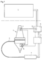
- the structure of the laser processing head 2 is shown in detail in FIG. 2. It comprises two parts which are movably connected to one another to a certain extent, namely the actual tool shaft 12 and a lower part 14 which contains the laser optics.
- a slide 16 loaded with a plate spring 15, in which the clamping receiver 17 provided with an annular flute is seated.
- the self-aligning bearing for mounting the lower part 14 which has the laser optics.
- the self-aligning bearing comprises a bearing shell 19 in the form of a hollow cylindrical body, the upper bearing surface 20 of which is hollow.
- the bearing shell 19 rests on an externally threaded washer 21 which is screwed into a corresponding threaded hole in the tool shank.
- the bearing shell 19 can be adjusted so that the laser beam emerging from the laser head runs coaxially to the spindle axis of rotation of the machine tool.
- the lower part 14 of the laser head 2 is pivoted in all directions.
- the angular position of the lower part 14, and thus the precise alignment of the laser beam, can be adjusted using three screws 28, for example.
- the light guide cable coming from the laser is connected laterally to the lower part 14 of the laser head.
- a connection socket 29 is provided on the side, into which the plug of the light guide cable is inserted.
- the laser beams strike the deflecting mirror 30 arranged in the lower part 14 and are deflected by the latter onto a lens or a lens system 31, through which the laser beams are focused.
- the laser head is provided with a cutting nozzle 32, through which the laser beam on the one hand and a working gas on the other hand exit.
- the connection for the working gas is not shown in the drawing.
- a welding attachment can also be used.
Abstract
Ein Laser-Bearbeitungskopf (2) für eine numerisch gesteuerte Werkzeugmaschine (1) ist zum Zweck der Auswechselung gegen ein mechanisches Bearbeitungswerkzeug mit einem Werkzeugschaft versehen, der dem Werkzeugschaft des mechanischen Bearbeitungswerkzeugs entspricht. Er besteht aus einem den Werkzeugschaft enthaltenden Teil und einem die Laser-Optik enthaltenden Teil, deren räumliche Lage zueinander einstellbar ist. Erforderliche Justiermaßnahmen können auf diese Weise am Laser-Kopf (2) selbst vorgenommen werden. Ein Kontrollschalter (9) im Werkzeugschaft, ein Lagesensor (10) in dem die Laser-Optik enthaltenden Teil und ein Sicherheitsschalter (13) in einer Werkzeugbox (6), die den Laser-Bearbeitungskopf (2) in seiner Wartestellung aufnimmt, sind in einem gemeinsamen Sicherheitskreis miteinander verknüpft. Der Sicherheitskreis stellt sicher, daß der Laser (4) nur dann eingeschaltet werden kann, wenn der Laser-Bearbeitungskopf (2) ordnungsgemäß eingespannt und ausgerichtet ist. <IMAGE>A laser processing head (2) for a numerically controlled machine tool (1) is provided with a tool shaft for the purpose of replacement with a mechanical processing tool, which tool shaft corresponds to the tool shaft of the mechanical processing tool. It consists of a part containing the tool shank and a part containing the laser optics, the spatial position of which can be adjusted relative to one another. In this way, necessary adjustment measures can be carried out on the laser head (2) itself. A control switch (9) in the tool shank, a position sensor (10) in the part containing the laser optics and a safety switch (13) in a tool box (6) which receives the laser processing head (2) in its waiting position are all in one common safety circuit linked together. The safety circuit ensures that the laser (4) can only be switched on when the laser processing head (2) is properly clamped and aligned. <IMAGE>
Description
Die Erfindung betrifft einen Laser-Bearbeitungskopf für eine numerisch gesteuerte Werkzeugmaschine, der zum Zweck der Auswechslung gegen ein mechanisches Bearbeitungswerkzeug mit einem mit dem Werkzeugträger der Werkzeugmaschine kuppelbaren, dem Werkzeugschaft des mechanischen Bearbeitungswerkzeugs entsprechenden und die koaxiale Anordnung des Laser-Kopfes zur Achse des mechanischen Bearbeitungswerkzeugs erlaubenden Werkzeugschaft versehen ist. Die Erfindung betrifft ferner eine Zusatzeinrichtung für eine numerisch gesteuerte Werkzeugmaschine mit einem derartigen mit dem Werkzeugträger der Werkzeugmaschine kuppelbaren Laser-Bearbeitungskopf.The invention relates to a laser processing head for a numerically controlled machine tool, which, for the purpose of replacement with a mechanical processing tool, can be coupled to the tool holder of the machine tool, corresponds to the tool shaft of the mechanical processing tool, and the coaxial arrangement of the laser head to the axis of the mechanical processing tool permitting tool shank is provided. The invention further relates to an additional device for a numerically controlled machine tool with such a laser processing head that can be coupled to the tool holder of the machine tool.
Aus der EP 0158866 B1 ist eine numerisch gesteuerte Werkzeugmaschine zur wahlweisen Bearbeitung eines Werkstücks mit einem mechanischen Bearbeitungswerkzeug oder mit einer Laser-Schneideinrichtung bekannt. Bei dieser bekannten Werkzeugmaschine sind das mechanische Bearbeitungswerkzeug, beispielsweise ein Stanzwerkzeug, und der Laser-Bearbeitungskopf jeweils mit einem gleich ausgebildeten Schaft versehen, mit dem sie in die Werkzeugaufnahme der Werkzeugmaschine eingesetzt werden. Wenn der Laser-Bearbeitungskopf in die Werkzeugaufnahme eingesetzt ist, entspricht die geometrische Achse des Laser-Kopfes der geometrischen Achse des mechanischen Bearbeitungswerkzeugs. Infolgedessen kann bei einer solchen Maschine unabhängig von dem jeweiligen Werkzeug dasselbe Programm verwendet werden.EP 0158866 B1 discloses a numerically controlled machine tool for optionally machining a workpiece with a mechanical machining tool or with a laser cutting device. In this known machine tool, the mechanical processing tool, for example a punching tool, and the laser processing head are each provided with an identically designed shaft with which they are inserted into the tool holder of the machine tool. If the laser processing head is inserted into the tool holder, the geometric axis of the laser head corresponds to the geometric axis of the mechanical processing tool. As a result, the same program can be used in such a machine regardless of the tool.
Bei dieser bekannten Werkzeugmaschine ist der auswechselbare Laser-Bearbeitungskopf als in sich starre Vorrichtung ausgebildet. Er besteht aus einem zylinderförmigen Hohlkörper und umfaßt eine gegen das Werkstück gerichtete Düse und eine Linsenfassung mit einer Linse, durch die die Laserstrahlen auf das Werkstück fokussiert werden. Die Laserstrahlen werden über einen außerhalb des Laser-Kopfes angeordneten Umlenkspiegel in die Achsrichtung umgelenkt und durch den zylindrischen Hohlkörper hindurch auf die Linse gerichtet.In this known machine tool, the interchangeable laser processing head is designed as a rigid device. It consists of a cylindrical hollow body and comprises a nozzle directed against the workpiece and a lens holder with a lens through which the laser beams are focused on the workpiece. The laser beams are deflected in the axial direction via a deflection mirror arranged outside the laser head and directed through the cylindrical hollow body onto the lens.
Es ist ferner eine Einrichtung der eingangs genannten Art bekannt, bei der die Laserstrahlung von dem Laser mittels eines Lichtleitkabels auf den Laser-Bearbeitungskopf übertragen wird (JP 3-165983 A, Patents Abstracts of Japan,1991,Vol.15/No.404, Sec. M-1168)
Der Erfindung liegt die Aufgabe zugrunde, eine Werkzeugmaschine der eingangs genannten Art dahingehend weiterzuentwickeln, daß eventuelle Verschiebungen der geometrischen Achse des Laserstrahls und/oder winkelmäßige Ablenkungen des Laserstrahls, die aufgrund von Dejustierungen im mechanischen und im optischen System einer solchen Maschine nicht immer vermeidbar sind, jederzeit auf verhältnismäßig einfache Weise korrigiert werden können.A device of the type mentioned at the outset is also known, in which the laser radiation is transmitted from the laser to the laser processing head by means of a light guide cable (JP 3-165983 A, Patents Abstracts of Japan, 1991, Vol.15 / No.404, Sec.M-1168)
The invention is based on the object of further developing a machine tool of the type mentioned at the outset such that possible displacements of the geometric axis of the laser beam and / or angular deflections of the laser beam which cannot always be avoided due to misalignments in the mechanical and optical system of such a machine, can be corrected at any time in a relatively simple manner.
Gemaß der Erfindung wird diese Aufgabe dadurch gelöst, daß der Laser-Bearbeitungskopf aus einem den Werkzeugschaft enthaltenden Teil und einem die Laseroptik enthaltenden Teil besteht, deren räumliche Lage zueinander einstellbar ist.According to the invention, this object is achieved in that the laser machining head from a containing the tool shank Part and a part containing the laser optics, the spatial position of each other is adjustable.
Mit Hilfe eines erfindungsgemäß ausgebildeten Laser-Bearbeitungskopfes ist es also möglich, gegebenenfalls erforderliche Justierungsmaßnahmen auf einfache Weise an dem Laser-Kopf selbst vorzunehmen, ohne daß an der Werkzeugmaschine als solcher irgendwelche Eingriffe vorgenommen werden müssen. Da der Laser-Kopf in der Regel leicht zugänglich ist, können solche Justierungsmaßnahmen ohne größeren Aufwand und verhältnismäßig schnell durchgeführt werden.With the aid of a laser machining head designed according to the invention, it is therefore possible to carry out any necessary adjustment measures in a simple manner on the laser head itself, without any intervention having to be carried out on the machine tool as such. Since the laser head is usually easily accessible, such adjustment measures can be carried out relatively quickly and without great effort.
Bei dem Werkzeugschaft, mit dem der Laser-Bearbeitungskopf in die Werkzeugaufnahme, das heißt in das Kupplungsstück im Werkzeugträger, eingesetzt wird, kann es sich zweckmäßigerweise um einen Werkzeugschaft mit den genormten Abmessungen eines Werkzeugschaftes für ein spanabhebendes Werkzeug handeln, so daß der erfindungsgemäße Laser-Bearbeitungskopf in einen üblichen genormten Werkzeugträger einer Werkzeugmaschine eingespannt werden kann.The tool shank with which the laser machining head is inserted into the tool holder, that is to say into the coupling piece in the tool holder, can expediently be a tool shank with the standardized dimensions of a tool shank for a cutting tool, so that the laser tool according to the invention Machining head can be clamped in a standard tool holder of a machine tool.
Vorteilhafterweise sind in Weiterbildung der Erfindung der den Werkzeugschaft enthaltende Teil und der die Laser-Optik enthaltende Teil des Laser-Bearbeitungskopfes über ein Pendellager miteinander verbunden, wobei die Winkellage der beiden Teile zueinander durch Justierschrauben einstellbar ist.Advantageously, in a further development of the invention, the part containing the tool shank and the part of the laser machining head containing the laser optics are connected to one another via a self-aligning bearing, the angular position of the two parts relative to one another being adjustable by means of adjusting screws.
Bei Verbindung der beiden Teile des Laser-Bearbeitungskopfes über ein Pendellager ist zweckmäßigerweise die in dem den Werkzeugschaft aufweisenden Teil angeordnete Lagerschale des Pendellagers durch Justierschrauben senkrecht zur Achsrichtung des Werkzeugträgers der Werkzeugmaschine einstellbar.When the two parts of the laser machining head are connected via a self-aligning bearing, the bearing shell of the self-aligning bearing arranged in the part having the tool shank is expediently adjusted by adjusting screws perpendicular to the axial direction of the tool holder of the machine tool adjustable.
Eine weitere vorteilhafte Ausgestaltung der Erfindung besteht darin, daß die Laserstrahlen von einem stationär angeordneten Laser auf den Laser-Bearbeitungskopf über ein Lichtleitkabel übertragen werden, das an den Laser-Bearbeitungskopf seitlich unter einem rechten Winkel zur Richtung des aus dem Laser-Bearbeitungskopf austretenden Laserstrahls angekoppelt ist, und daß zum Umlenken der Laserstrahlen in die axiale Richtung des Werkzeugträgers ein optisches System in dem Laser-Bearbeitungskopf angeordnet ist.A further advantageous embodiment of the invention consists in that the laser beams are transmitted from a stationary laser to the laser processing head via a light guide cable which is coupled to the laser processing head laterally at a right angle to the direction of the laser beam emerging from the laser processing head and that for deflecting the laser beams in the axial direction of the tool carrier, an optical system is arranged in the laser machining head.
Die Erfindung kann insbesondere auch in der Weise verwirklicht werden, daß ein Nachrüstsatz für eine numerisch gesteuerte Werkzeugmaschine bereitgestellt wird, der einen mit einem mit dem Werkzeugträger der Werkzeugmaschine kuppelbaren Werkzeugschaft versehenen Laser-Bearbeitungskopf, einen mit dem Laser-Bearbeitungskopf über ein Lichtleitkabel verbundenen Laser, eine den Laser-Bearbeitungskopf in der Wartestellung aufnehmende Werkzeugbox und eine den Laser und die Werkzeugmaschine ansteuernde Steuerschaltung umfaßt, wobei der Laser-Bearbeitungkopf aus einem den Werkzeugschaft enthaltenden Teil und einem die Laseroptik enthaltenden Teil besteht, deren räumliche Lage zueinander einstellbar ist, daß der Laser-Bearbeitungskopf einen Kontrollschalter zur Kontrolle der Einspannung und einen Lagesensor zur Erkennung der Einspannlage aufweist, und daß der Kontrollschalter und/oder der Lagesensor eine einen Teil der Steuerschaltung bildende Sicherheitsschaltung für die Einschaltung des Lasers ansteuern.The invention can in particular also be implemented in such a way that a retrofit kit for a numerically controlled machine tool is provided which has a laser machining head provided with a tool shaft that can be coupled to the tool holder of the machine tool, comprises a tool box accommodating the laser processing head in the waiting position and a control circuit controlling the laser and the machine tool, the laser processing head consisting of a part containing the tool shaft and a part containing the laser optics, the spatial position of which can be adjusted relative to one another such that the laser -Processing head has a control switch for controlling the clamping and a position sensor for detecting the clamping position, and that the control switch and / or the position sensor forms a part of the control circuit safety circuit for switching on d drive it laser.
Durch einen derartigen Nachrüstsatz kann praktisch jede für die rein mechanische Bearbeitung eines Werkstücks ausgerüstete Werkzeugmaschine in außerordentlich kostengünstiger Weise kurzfristig in eine Laser-Bearbeitungsmaschine umgerüstet werden. Durch Auswechseln des Laser-Bearbeitungskopfes gegen ein mechanisches Bearbeitungswerkzeug kann die Maschine kurzfristig wieder in eine mechanische Bearbeitungsmaschine umgewandelt werden.With such a retrofit kit, practically anyone can use it purely mechanical processing of a workpiece equipped machine tool can be converted into a laser processing machine at short notice in an extremely cost-effective manner. By replacing the laser processing head with a mechanical processing tool, the machine can be quickly converted back into a mechanical processing machine.
Weitere vorteilhafte Weiterbildungen der Erfindung ergeben sich aus den Unteransprüchen und aus der nachfolgenden Beschreibung eines bevorzugten Ausführungsbeispiels anhand der Zeichnungen.Further advantageous developments of the invention result from the subclaims and from the following description of a preferred exemplary embodiment with reference to the drawings.
Von den Zeichnungen zeigt
- Fig. 1
- eine erfindungsgemäße Zusatzeinrichtung für eine numerisch gesteuerte Werkzeugmaschine in einer schematischen Gesamtdarstellung, und
- Fig. 2
- den erfindungsgemäßen Laser-Bearbeitungskopf, teilweise im Schnitt.
- Fig. 1
- an additional device according to the invention for a numerically controlled machine tool in a schematic overall view, and
- Fig. 2
- the laser processing head according to the invention, partly in section.
In der schematischen Darstellung der Fig. 1 ist die Werkzeugmaschine 1 beispielsweise eine numerisch gesteuerte Fräsmaschine, bei der ein Kreuzschlitten mit einem Werkzeugträger versehen ist, der eine innerhalb des Werkzeugträgers konzentrisch zu diesem angeordnete und von einem Elektromotor angetriebene Werkzeugspindel aufweist. Die Werkzeugspindel ist mit dem rotierenden Fräswerkzeug gekoppelt, sobald das Fräswerkzeug in dem Werkzeugträger befestigt ist. Stattdessen kann aber auch die in Drehung versetzbare Werkzeugspindel als solche unmittelbar als Werkzeugträger dienen. Bei der Werkzeugmaschine 1 kann es sich aber auch beispielsweise um eine numerisch gesteuerte Drehbank handeln, bei der das Werkzeug auf einem Kreuzschlitten angeordnet ist und längs und quer zur Drehachse des eingespannten und in Rotation versetzten Werkstücks verschoben wird.In the schematic representation of FIG. 1, the
Im Fall einer CNC-Fräsmaschine, für die die Erfindung im folgenden näher beschrieben wird, erfolgt mit Hilfe der numerischen Steuerung, die bei der schematischen Darstellung in die Werkzeugmaschine 1 integriert ist, sowohl die X-Y-Wegsteuerung des Kreuzschlittens als auch die Ansteuerung des Antriebsmotors für die Werkzeugspindel und die Ansteuerung der übrigen Antriebsmotoren, beispielsweise des Antriebsmotors für die Kühlflüssigkeit bei der mechanischen Bearbeitung und des Antriebsmotors des das Arbeitsgas liefernden Ventilators beim Einsatz des Laser-Bearbeitungskopfes.In the case of a CNC milling machine, for which the invention is described in more detail below, both the XY travel control of the cross slide and the control of the drive motor for are carried out with the aid of the numerical control, which is integrated in the schematic representation in the
Der Werkzeugträger der Fräsmaschine ist mit einer genormten Spannkupplung versehen, beispielsweise für einen SK40-Steilkegel. Insoweit handelt es sich vorzugsweise um eine übliche Werkzeugmaschine, wie sie für die spanabhebende Bearbeitung von Werkstücken Verwendung findet und auf dem Markt erhältlich ist.The tool carrier of the milling machine is equipped with a standardized clamping coupling, for example for a SK40 steep taper. To this extent, it is preferably a conventional machine tool, such as is used for the machining of workpieces and is available on the market.
Mit dem Werkzeugträger der Werkzeugmaschine 1 wird anstelle eines üblichen spanabhebenden Bearbeitungswerkzeugs der mit einem dem Kupplungsstück des Werkzeugträgers entsprechenden Werkzeugschaft versehene Laser-Bearbeitungskopf 2 verspannt, dessen Aufbau später noch im einzelnen beschrieben wird. An den Laser-Bearbeitungskopf 2 ist ein flexibles Lichtleitkabel 3 angekoppelt, durch das die im Laser 4 erzeugten Laserstrahlen dem Laser-Bearbeitungskopf 2 zugeführt werden. Der Laser 4 kann an geeigneter Stelle an der Werkzeugmaschine 1 ortsfest angeordnet werden.Instead of a conventional machining tool, the tool holder of the
Um den ordnungsgemäßen Betrieb der Maschine zu gewährleisten und um mögliche Gefahrenquellen auszuschließen, ist außer dem Laser-Bearbeitungskopf 2, dem Laser 4 und der Laser-Steuerung 5 eine Sicherheitseinrichtung vorgesehen, die eine Werkzeugbox 6 umfaßt und mit der Laser-Steuerung 5 verbunden ist. Die Werkzeugbox 6 dient dazu, den Laser-Bearbeitungskopf 2 aufzunehmen, wenn er nicht benutzt wird und nicht mit dem Werkzeugträger verspannt ist. Zu diesem Zweck ist die Werkzeugbox auf ihrer Oberseite mit einer dem Laser-Bearbeitungskopf 2 angepaßten Vertiefung versehen, in die der Laser-Kopf 2 eingesetzt wird. In der Werkzeugbox 6 sind ein oder mehrere Sicherheitsschalter 13 angeordnet, die durch den Laser-Kopf 2 betätigt werden, wenn dieser sich in der Werkzeugbox befindet. Zu der Sicherheitseinrichtung gehören ferner ein in dem Laser-Kopf 2 angeordneter Kontrollschalter 9. Dieser Kontrollschalter 9 erkennt, ob der Laser-Kopf 2 ordnungsgemäß im Werkzeugträger eingespannt ist. Ferner gehört zu der Sicherheitseinrichtung ein Lagesensor 10, der nur dann aktiviert wird, wenn der den Laserstrahl aussendende Teil des Laser-Kopfes 2 exakt in der gewünschten Arbeitsstellung ausgerichtet ist, in der die Bedienungsperson und die Umgebung der Maschine durch geeignete Sicherheitsvorkehrungen geschützt sind.In order to ensure the proper operation of the machine and to rule out possible sources of danger, in addition to the
Der bzw. die Sicherheitsschalter 13 in der Werkzeugbox 6, der Kontrollschalter 9 in dem den Werkzeugschaft aufweisenden Teil des Laser-Kopfes 2 und der Lagesensor 10 in dem die Laser-Optik enthaltenden Teil des Laser-Kopfes 2 sind in einem gemeinsamen Sicherheitskreis derart miteinander verknüpft, daß die folgenden Sicherheitskriterien erfüllt sind:
- a) Der Laser 4 kann nicht eingeschaltet werden, solange der Laser-
Kopf 2 sich in derWerkzeugbox 6 befindet; - b) der Laser 4 kann nur dann eingeschaltet werden, wenn der
Kontrollschalter 9 im Laser-Kopf 2 geschlossen ist, das heißt, wenn der Laser-Kopf 2 in der Werkzeugmaschine eingespannt ist; - c) der Laser 4 kann ferner nur dann eingeschaltet werden, wenn die Kontakte des
Lagesensors 10 im Laser-Kopf 2 geschlossen sind, und - d) der Antriebsmotor für eine Arbeitsspindel kann nur dann eingeschaltet werden, wenn sich der Laser-
Bearbeitungskopf 2 in derWerkzeugbox 6 befindet, sofern es sich um eine Werkzeugmaschine mit sich drehender Arbeitsspindel handelt.
- a) The
laser 4 cannot be switched on as long as thelaser head 2 is in thetool box 6; - b) the
laser 4 can only be switched on when thecontrol switch 9 in thelaser head 2 is closed, that is to say when thelaser head 2 is clamped in the machine tool; - c) the
laser 4 can also only be switched on when the contacts of theposition sensor 10 in thelaser head 2 are closed, and - d) the drive motor for a work spindle can only be switched on when the
laser processing head 2 is in thetool box 6, provided that it is a machine tool with a rotating work spindle.
Durch den diese Kriterien erfüllenden Sicherheitskreis wird sichergestellt, daß einerseits die Bedienungsperson der Maschine und das Arbeitsumfeld durch den Laserstrahl nicht gefährdet werden, da der Laser 4 solange nicht eingeschaltet werden kann, wie der Laser-Kopf 2 nicht fest eingespannt ist und der Laserstrahl nicht die gewünschte Richtung aufweist, das heißt bei einer Fräsmaschine nicht genau nach unten ausgerichtet ist. Andererseits wird zusätzlich sichergestellt, daß die Arbeitsspindel, und damit der Laser-Kopf 2, in seiner Arbeitsstellung nicht in Drehung versetzt wird.The safety circuit fulfilling these criteria ensures that, on the one hand, the operator of the machine and the working environment are not endangered by the laser beam, since the
Die von dieser Sicherheitsschaltung kommenden Steuersignale können zweckmäßigerweise noch andere zusätzliche Funktionen übernehmen. So können diese Steuersignale außer zum Ein- und Ausschalten des Lasers und des Antriebsmotors der Arbeitsspindel noch zum Ein- und Ausschalten des Antriebsmotors der Kühlmittelpumpe und zum Ein- und Ausschalten des Antriebsmotors der das Arbeitsgas für den Laser-Kopf fördernden Gaspumpe benutzt werden. Mit diesen von der Sicherheitsschaltung kommenden Steuersignalen können mit anderen Worten auch andere Einrichtungen der Werkzeugmaschine umgeschaltet werden, deren Umschaltung beim Wechsel vom mechanischen Betrieb der Maschine auf den Laser-Betrieb, und umgekehrt, erforderlich oder zweckmäßig ist.The control signals coming from this safety circuit can expediently perform other additional functions. This means that these control signals can be used in addition to switching the laser and the drive motor of the work spindle on and off can still be used to switch the drive motor of the coolant pump on and off and to switch the drive motor of the gas pump delivering the working gas for the laser head on and off. In other words, these control signals coming from the safety circuit can also be used to switch over other devices of the machine tool, the switchover of which is necessary or expedient when changing from mechanical operation of the machine to laser operation and vice versa.
Der Aufbau des Laser-Bearbeitungskopfes 2 ergibt sich im einzelnen aus der Fig. 2. Er umfaßt zwei Teile, die in einem bestimmten Ausmaß miteinander beweglich verbunden sind, nämlich den eigentlichen Werkzeugschaft 12 und einen unteren Teil 14, der die Laser-Optik enthält. Innerhalb des Werkzeugschaftes 12 ist ein mit einer Tellerfeder 15 belasteter Schieber 16 angeordnet, in dem der mit einer ringförmigen Spannut versehene Spannaufnehmer 17 sitzt. Unterhalb des Schiebers 16 ist innerhalb des Werkzeugschaftes 12 der Kontrollschalter 9 angeordnet, der durch den Schieber 16 betätigt wird, wenn der Werkzeugschaft 12 ordnungsgemäß eingespannt ist.The structure of the
Innerhalb des Werkzeugschaftes 12 befindet sich das Pendellager für die Lagerung des unteren, die Laser-Optik aufweisenden Teils 14. Das Pendellager umfaßt eine Lagerschale 19 in Form eines Hohlzylinderkörpers, dessen obere Lagerfläche 20 hohlkugelförmig ausgebildet ist. Die Lagerschale 19 ruht auf einer mit Außengewinde versehenen Scheibe 21, die in eine entsprechende Gewindebohrung im Werkzeugschaft eingeschraubt ist. Mit Hilfe von beispielsweise drei radial im Werkzeugschaft angeordneten Schrauben 29 kann die Lagerschale 19 einjustiert werden, so daß der aus dem Laser-Kopf austretende Laserstrahl koaxial zur Spindeldrehachse der Werkzeugmaschine verläuft.Within the
Auf der Lagerschale 19 ruht ein kugelkalottenförmiges Lagerstück 25, an dem eine Stange 26 befestigt ist, die ihrerseits an dem die Laser-Optik aufweisenden unteren Teil 14 befestigt ist. Der untere Teil 14 des Laser-Kopfes 2 ist auf diese Weise in allen Richtungen pendelnd gelagert. Die Winkelstellung des unteren Teils 14, und damit die genaue Ausrichtung des Laserstrahls, kann mit Hilfe von beispielsweise drei Schrauben 28 einjustiert werden.On the bearing shell 19 rests a spherical cap-shaped
Das von dem Laser kommende Lichtleitkabel wird seitlich an den unteren Teil 14 des Laser-Kopfes angeschlossen. Zu diesem Zweck ist seitlich eine Anschlußbuchse 29 vorgesehen, in die der Stecker des Lichtleitkabels eingeführt wird. Die Laserstrahlen treffen auf den in dem unteren Teil 14 angeordneten Umlenkspiegel 30 und werden von diesem auf eine Linse oder ein Linsensystem 31 umgelenkt, durch das die Laserstrahlen fokussiert werden. Im dargestellten Fall ist der Laser-Kopf mit einer Schneiddüse 32 versehen, durch die einerseits der Laserstrahl und andererseits ein Arbeitsgas austritt. Der Einfachheit halber ist der Anschluß für das Arbeitsgas in der Zeichnung nicht dargestellt. Anstelle einer Schneiddüse kann beispielsweise auch ein Schweißvorsatz eingesetzt werden.The light guide cable coming from the laser is connected laterally to the
Claims (12)
Applications Claiming Priority (2)
| Application Number | Priority Date | Filing Date | Title |
|---|---|---|---|
| DE4235592 | 1992-10-22 | ||
| DE4235592A DE4235592C1 (en) | 1992-10-22 | 1992-10-22 | Laser processing head and additional device for a numerically controlled machine tool |
Publications (2)
| Publication Number | Publication Date |
|---|---|
| EP0593941A1 true EP0593941A1 (en) | 1994-04-27 |
| EP0593941B1 EP0593941B1 (en) | 1995-03-15 |
Family
ID=6471037
Family Applications (1)
| Application Number | Title | Priority Date | Filing Date |
|---|---|---|---|
| EP93115505A Expired - Lifetime EP0593941B1 (en) | 1992-10-22 | 1993-09-25 | Laser operating head and auxiliary equipment for a numerically controlled tool machine |
Country Status (5)
| Country | Link |
|---|---|
| US (1) | US5508490A (en) |
| EP (1) | EP0593941B1 (en) |
| JP (1) | JPH06339785A (en) |
| AT (1) | ATE119816T1 (en) |
| DE (2) | DE4235592C1 (en) |
Cited By (2)
| Publication number | Priority date | Publication date | Assignee | Title |
|---|---|---|---|---|
| US5728051A (en) * | 1996-02-27 | 1998-03-17 | Chi; Stephen | Massager having removable massage elements |
| CN105612026A (en) * | 2013-09-13 | 2016-05-25 | 德马吉森股份公司 | Numerically controlled machine tool |
Families Citing this family (28)
| Publication number | Priority date | Publication date | Assignee | Title |
|---|---|---|---|---|
| IT1277080B1 (en) * | 1995-12-14 | 1997-11-04 | Salvagnini Italia Spa | FOCUSING HEAD OF A LASER BEAM EQUIPPED WITH A FOCUSING LENS FOR A METAL WORKING MACHINE |
| DE19853365A1 (en) * | 1998-11-19 | 2000-05-25 | Schuler Pressen Gmbh & Co | Method and device for forming |
| AU5168000A (en) * | 1999-05-26 | 2000-12-12 | Ii-Vi Incorporated | Improved optical contacting method and apparatus |
| US6658316B1 (en) | 1999-12-30 | 2003-12-02 | Abb Technology Ag | Parametric programming of robots and automated machines for manufacturing electrical enclosures |
| AU2221000A (en) | 1999-12-30 | 2001-07-16 | Abb Power T & D Company Inc. | Parametric programming of laser cutting system |
| DE10060176B4 (en) * | 2000-12-04 | 2008-06-19 | Precitec Kg | Laser processing head |
| US11228735B2 (en) * | 2003-01-14 | 2022-01-18 | Tseng-Lu Chien | LED or laser project light has more than 1 functions |
| JP4390627B2 (en) * | 2004-05-28 | 2009-12-24 | ヤマザキマザック株式会社 | Laser hardening tool |
| US20060006157A1 (en) * | 2004-07-09 | 2006-01-12 | Ingersoll Machine Tools, Inc. | Method and apparatus for repairing or building up surfaces on a workpiece while the workpiece is mounted on a machine tool |
| DE502004008645D1 (en) * | 2004-08-06 | 2009-01-22 | Trumpf Werkzeugmaschinen Gmbh | Laser processing head |
| JP2006281390A (en) * | 2005-04-01 | 2006-10-19 | Jtekt Corp | Combined machine tool, and method for machining workpiece using the same |
| DE102006003682A1 (en) * | 2006-01-24 | 2007-07-26 | Jenoptik Automatisierungstechnik Gmbh | Combined device for material processing with a milling cutter and a laser |
| JP2007313515A (en) * | 2006-05-23 | 2007-12-06 | Jtekt Corp | Compound machining apparatus, and machining method using the same |
| DE102008056278A1 (en) * | 2008-10-25 | 2010-04-29 | Kjellberg Finsterwalde Plasma Und Maschinen Gmbh | System for the thermal processing of workpieces |
| DE102008055971A1 (en) * | 2008-11-05 | 2010-05-06 | Komet Group Gmbh | Machining center with rotary transformer for electrical energy |
| US11476626B2 (en) | 2008-11-12 | 2022-10-18 | Aaron Chien | DC powered remote control LED light-bar assembly |
| US20100271010A1 (en) * | 2009-04-27 | 2010-10-28 | Visible Assets, Inc | Tool Sensor, System and Method |
| CN102166685B (en) * | 2011-04-27 | 2013-12-25 | 华中科技大学 | Three-coordinate galvanometer scanning laser processing head |
| JP6139918B2 (en) * | 2013-03-06 | 2017-05-31 | 株式会社アマダホールディングス | Laser processing machine |
| US20140283987A1 (en) * | 2013-03-19 | 2014-09-25 | Systems And Materials Research Corporation | Method and apparatus to apply a fill material to a substrate |
| US20170057011A1 (en) * | 2014-02-20 | 2017-03-02 | Dmg Mori Advanced Solutions Development | A Processing Head for a Hybrid Additive/Subtractive Manufacturing Center |
| CN105643366A (en) * | 2016-04-12 | 2016-06-08 | 莱芜钢铁集团有限公司 | Auxiliary component for levelness correction of horizontal guide rail of machine tool and method |
| CN105773303A (en) * | 2016-04-12 | 2016-07-20 | 莱芜钢铁集团有限公司 | Milling machine rectilinear rising and falling precision correction auxiliary component and method |
| US10464165B2 (en) * | 2016-08-02 | 2019-11-05 | Nakamura-Tome Precision Industry Co., Ltd. | Combined machining apparatus having a laser machining head |
| WO2019055049A1 (en) * | 2017-09-18 | 2019-03-21 | Robert Bosch Tool Corporation | Method to ensure safety critical functionality for an electrically powered machine |
| US11931823B2 (en) | 2019-02-05 | 2024-03-19 | Dukane Ias, Llc | Systems and methods for laser-welding a workpiece with a laser beam that reaches inaccessible areas of the workpiece using multiple reflecting parts |
| US10926355B2 (en) | 2019-02-05 | 2021-02-23 | Dukane Ias, Llc | Systems and methods for laser-welding tubular components using a single, fixed optical reflector with multiple reflecting surfaces |
| US11819940B2 (en) | 2019-02-05 | 2023-11-21 | Dukane Ias, Llc | Systems and methods for laser-welding a workpiece with a laser beam that reaches inaccessible areas of the workpiece using multiple reflecting parts |
Citations (5)
| Publication number | Priority date | Publication date | Assignee | Title |
|---|---|---|---|---|
| JPS56168918A (en) * | 1980-05-31 | 1981-12-25 | Amada Co Ltd | Laser cutter |
| EP0158866B1 (en) * | 1984-03-24 | 1989-06-28 | Trumpf GmbH & Co | Machine tool for processing a work piece mechanically and thermally |
| JPH03165983A (en) * | 1989-11-22 | 1991-07-17 | Amada Co Ltd | Combined machine of laser beam and punch |
| JPH04197589A (en) * | 1990-11-28 | 1992-07-17 | Amada Co Ltd | Laser punch press, laser working head unit for the laser punch press, device for connecting laser working head unit with laser oscillator and beam detector used in adjusting laser beam path |
| WO1992016334A1 (en) * | 1991-03-15 | 1992-10-01 | Fanuc Ltd | Laser-workable combination type machine tool |
Family Cites Families (11)
| Publication number | Priority date | Publication date | Assignee | Title |
|---|---|---|---|---|
| FR2556262B1 (en) * | 1983-12-09 | 1987-02-20 | Ressencourt Hubert | THE PRESENT INVENTION CONCERNS A CENTER FOR FORMING SHEET MATERIALS WITH NUMERICAL CONTROL |
| JPS63503213A (en) * | 1986-03-25 | 1988-11-24 | レーザー・ラブ・リミテッド | work head device |
| JPS63104794A (en) * | 1986-10-21 | 1988-05-10 | Mitsubishi Electric Corp | Laser beam machine |
| DE3814074A1 (en) * | 1988-04-26 | 1989-11-09 | Baasel Carl Lasertech | Laser nozzle tip |
| JPH01321089A (en) * | 1988-06-22 | 1989-12-27 | Mitsubishi Electric Corp | Machining head for laser beam machine |
| JPH02224887A (en) * | 1989-02-28 | 1990-09-06 | Komatsu Ltd | Laser processing device |
| DE3939812C2 (en) * | 1989-12-01 | 1993-11-11 | Deutsche Aerospace | Laser soldering system for SMD elements |
| JPH04111989A (en) * | 1990-08-31 | 1992-04-13 | Mitsubishi Electric Corp | Laser beam machine |
| WO1992016314A1 (en) * | 1991-03-12 | 1992-10-01 | Haakansson Lars | A device for cleaning objects, preferably of metal |
| DE4143414C2 (en) * | 1991-09-03 | 1996-06-20 | Precitec Gmbh | Tool head with automatically adjustable focusing optics |
| JP2804206B2 (en) * | 1992-09-22 | 1998-09-24 | 三菱電機株式会社 | Laser processing head |
-
1992
- 1992-10-22 DE DE4235592A patent/DE4235592C1/en not_active Expired - Fee Related
-
1993
- 1993-09-25 DE DE59300107T patent/DE59300107D1/en not_active Expired - Fee Related
- 1993-09-25 EP EP93115505A patent/EP0593941B1/en not_active Expired - Lifetime
- 1993-09-25 AT AT93115505T patent/ATE119816T1/en not_active IP Right Cessation
- 1993-10-14 US US08/136,510 patent/US5508490A/en not_active Expired - Fee Related
- 1993-10-19 JP JP5260724A patent/JPH06339785A/en active Pending
Patent Citations (5)
| Publication number | Priority date | Publication date | Assignee | Title |
|---|---|---|---|---|
| JPS56168918A (en) * | 1980-05-31 | 1981-12-25 | Amada Co Ltd | Laser cutter |
| EP0158866B1 (en) * | 1984-03-24 | 1989-06-28 | Trumpf GmbH & Co | Machine tool for processing a work piece mechanically and thermally |
| JPH03165983A (en) * | 1989-11-22 | 1991-07-17 | Amada Co Ltd | Combined machine of laser beam and punch |
| JPH04197589A (en) * | 1990-11-28 | 1992-07-17 | Amada Co Ltd | Laser punch press, laser working head unit for the laser punch press, device for connecting laser working head unit with laser oscillator and beam detector used in adjusting laser beam path |
| WO1992016334A1 (en) * | 1991-03-15 | 1992-10-01 | Fanuc Ltd | Laser-workable combination type machine tool |
Non-Patent Citations (3)
| Title |
|---|
| PATENT ABSTRACTS OF JAPAN vol. 006, no. 056 (M - 121) 13 April 1982 (1982-04-13) * |
| PATENT ABSTRACTS OF JAPAN vol. 015, no. 404 (M - 1168) 15 October 1991 (1991-10-15) * |
| PATENT ABSTRACTS OF JAPAN vol. 016, no. 529 (M - 1332) 29 October 1992 (1992-10-29) * |
Cited By (3)
| Publication number | Priority date | Publication date | Assignee | Title |
|---|---|---|---|---|
| US5728051A (en) * | 1996-02-27 | 1998-03-17 | Chi; Stephen | Massager having removable massage elements |
| CN105612026A (en) * | 2013-09-13 | 2016-05-25 | 德马吉森股份公司 | Numerically controlled machine tool |
| CN105612026B (en) * | 2013-09-13 | 2019-08-06 | 德马吉森股份公司 | Numerically-controlled machine tool |
Also Published As
| Publication number | Publication date |
|---|---|
| US5508490A (en) | 1996-04-16 |
| EP0593941B1 (en) | 1995-03-15 |
| DE59300107D1 (en) | 1995-04-20 |
| DE4235592C1 (en) | 1994-01-27 |
| ATE119816T1 (en) | 1995-04-15 |
| JPH06339785A (en) | 1994-12-13 |
Similar Documents
| Publication | Publication Date | Title |
|---|---|---|
| EP0593941B1 (en) | Laser operating head and auxiliary equipment for a numerically controlled tool machine | |
| DE60217629T2 (en) | Laser positioning system for machine for machining holes | |
| EP1034875B1 (en) | Workpiece machining machine tool with cutting tools and laser beam | |
| EP3484656B1 (en) | Method and laser machining device for laser welding of a first and a second workpiece section | |
| DE102018005097B4 (en) | FIBER SELECTION APPARATUS AND LASER APPARATUS | |
| DE2933700A1 (en) | MACHINE TOOL WITH MELT CUTTING DEVICE | |
| EP0707920A2 (en) | Compact laser processing head for laser processing of material, with an integrated on-line track control | |
| EP1023140A1 (en) | Welding device for two work pieces to be joined together by a weld seam which is closed in itself | |
| WO1999012696A1 (en) | Automatic welding machine | |
| CH622457A5 (en) | ||
| DE3543897A1 (en) | ROBOT LASER SYSTEM | |
| EP2036652A1 (en) | Laser welding device with a manually movable holding means for the optic processing head | |
| DE202017101590U1 (en) | Device for guiding a laser beam onto a workpiece | |
| EP3081324A1 (en) | Long turning machine with two nc-controlled processing axes and method for machining workpieces on a long turning machine with two nc-controlled processing axes | |
| DE10144256B4 (en) | Short-time arc welding system and method | |
| DE3523887C2 (en) | ||
| DE3634018C2 (en) | ||
| DE3822565A1 (en) | Automatic clamping device | |
| DE4242057C2 (en) | Laser processing plant | |
| EP3787833A1 (en) | Laser processing head and laser processing machine | |
| DE19813419C2 (en) | Welding torch system, especially for MIG / MAG welding with automatic welding machines | |
| DE19531484C2 (en) | Device for adjusting the position of portable tools | |
| DE19609511A1 (en) | Auxiliary system for hand-guided tool with guide unit for tool holder | |
| DE102020211533B3 (en) | Measuring instrument for a laser tool, laser tool and workpiece processing device, and method for measuring a distance | |
| EP0223076A1 (en) | Fully automatic robot system |
Legal Events
| Date | Code | Title | Description |
|---|---|---|---|
| PUAI | Public reference made under article 153(3) epc to a published international application that has entered the european phase |
Free format text: ORIGINAL CODE: 0009012 |
|
| AK | Designated contracting states |
Kind code of ref document: A1 Designated state(s): AT BE CH DE DK ES FR GB IT LI LU NL SE |
|
| 17P | Request for examination filed |
Effective date: 19940420 |
|
| 17Q | First examination report despatched |
Effective date: 19940823 |
|
| GRAA | (expected) grant |
Free format text: ORIGINAL CODE: 0009210 |
|
| AK | Designated contracting states |
Kind code of ref document: B1 Designated state(s): AT BE CH DE DK ES FR GB IT LI LU NL SE |
|
| PG25 | Lapsed in a contracting state [announced via postgrant information from national office to epo] |
Ref country code: NL Free format text: LAPSE BECAUSE OF FAILURE TO SUBMIT A TRANSLATION OF THE DESCRIPTION OR TO PAY THE FEE WITHIN THE PRESCRIBED TIME-LIMIT Effective date: 19950315 Ref country code: IT Free format text: LAPSE BECAUSE OF FAILURE TO SUBMIT A TRANSLATION OF THE DESCRIPTION OR TO PAY THE FEE WITHIN THE PRE;WARNING: LAPSES OF ITALIAN PATENTS WITH EFFECTIVE DATE BEFORE 2007 MAY HAVE OCCURRED AT ANY TIME BEFORE 2007. THE CORRECT EFFECTIVE DATE MAY BE DIFFERENT FROM THE ONE RECORDED.SCRIBED TIME-LIMIT Effective date: 19950315 Ref country code: GB Effective date: 19950315 Ref country code: FR Effective date: 19950315 Ref country code: ES Free format text: THE PATENT HAS BEEN ANNULLED BY A DECISION OF A NATIONAL AUTHORITY Effective date: 19950315 Ref country code: DK Effective date: 19950315 Ref country code: BE Effective date: 19950315 |
|
| REF | Corresponds to: |
Ref document number: 119816 Country of ref document: AT Date of ref document: 19950415 Kind code of ref document: T |
|
| REF | Corresponds to: |
Ref document number: 59300107 Country of ref document: DE Date of ref document: 19950420 |
|
| PG25 | Lapsed in a contracting state [announced via postgrant information from national office to epo] |
Ref country code: SE Effective date: 19950615 |
|
| EN | Fr: translation not filed | ||
| NLV1 | Nl: lapsed or annulled due to failure to fulfill the requirements of art. 29p and 29m of the patents act | ||
| GBV | Gb: ep patent (uk) treated as always having been void in accordance with gb section 77(7)/1977 [no translation filed] |
Effective date: 19950315 |
|
| PG25 | Lapsed in a contracting state [announced via postgrant information from national office to epo] |
Ref country code: AT Effective date: 19950925 |
|
| PG25 | Lapsed in a contracting state [announced via postgrant information from national office to epo] |
Ref country code: LU Free format text: LAPSE BECAUSE OF NON-PAYMENT OF DUE FEES Effective date: 19950930 Ref country code: LI Effective date: 19950930 Ref country code: CH Effective date: 19950930 |
|
| PLBE | No opposition filed within time limit |
Free format text: ORIGINAL CODE: 0009261 |
|
| STAA | Information on the status of an ep patent application or granted ep patent |
Free format text: STATUS: NO OPPOSITION FILED WITHIN TIME LIMIT |
|
| 26N | No opposition filed | ||
| REG | Reference to a national code |
Ref country code: CH Ref legal event code: PL |
|
| PGFP | Annual fee paid to national office [announced via postgrant information from national office to epo] |
Ref country code: DE Payment date: 19961210 Year of fee payment: 4 |
|
| PG25 | Lapsed in a contracting state [announced via postgrant information from national office to epo] |
Ref country code: DE Free format text: LAPSE BECAUSE OF NON-PAYMENT OF DUE FEES Effective date: 19980603 |