EP0593881A1 - A seat-support for sitting furniture - Google Patents
A seat-support for sitting furniture Download PDFInfo
- Publication number
- EP0593881A1 EP0593881A1 EP93113793A EP93113793A EP0593881A1 EP 0593881 A1 EP0593881 A1 EP 0593881A1 EP 93113793 A EP93113793 A EP 93113793A EP 93113793 A EP93113793 A EP 93113793A EP 0593881 A1 EP0593881 A1 EP 0593881A1
- Authority
- EP
- European Patent Office
- Prior art keywords
- seat support
- rocker
- support according
- seat
- backrest
- Prior art date
- Legal status (The legal status is an assumption and is not a legal conclusion. Google has not performed a legal analysis and makes no representation as to the accuracy of the status listed.)
- Ceased
Links
Images


Classifications
-
- A—HUMAN NECESSITIES
- A47—FURNITURE; DOMESTIC ARTICLES OR APPLIANCES; COFFEE MILLS; SPICE MILLS; SUCTION CLEANERS IN GENERAL
- A47C—CHAIRS; SOFAS; BEDS
- A47C1/00—Chairs adapted for special purposes
- A47C1/02—Reclining or easy chairs
- A47C1/031—Reclining or easy chairs having coupled concurrently adjustable supporting parts
- A47C1/032—Reclining or easy chairs having coupled concurrently adjustable supporting parts the parts being movably-coupled seat and back-rest
- A47C1/03255—Reclining or easy chairs having coupled concurrently adjustable supporting parts the parts being movably-coupled seat and back-rest with a central column, e.g. rocking office chairs
-
- A—HUMAN NECESSITIES
- A47—FURNITURE; DOMESTIC ARTICLES OR APPLIANCES; COFFEE MILLS; SPICE MILLS; SUCTION CLEANERS IN GENERAL
- A47C—CHAIRS; SOFAS; BEDS
- A47C1/00—Chairs adapted for special purposes
- A47C1/02—Reclining or easy chairs
- A47C1/031—Reclining or easy chairs having coupled concurrently adjustable supporting parts
- A47C1/032—Reclining or easy chairs having coupled concurrently adjustable supporting parts the parts being movably-coupled seat and back-rest
- A47C1/03261—Reclining or easy chairs having coupled concurrently adjustable supporting parts the parts being movably-coupled seat and back-rest characterised by elastic means
- A47C1/03266—Reclining or easy chairs having coupled concurrently adjustable supporting parts the parts being movably-coupled seat and back-rest characterised by elastic means with adjustable elasticity
-
- A—HUMAN NECESSITIES
- A47—FURNITURE; DOMESTIC ARTICLES OR APPLIANCES; COFFEE MILLS; SPICE MILLS; SUCTION CLEANERS IN GENERAL
- A47C—CHAIRS; SOFAS; BEDS
- A47C1/00—Chairs adapted for special purposes
- A47C1/02—Reclining or easy chairs
- A47C1/031—Reclining or easy chairs having coupled concurrently adjustable supporting parts
- A47C1/032—Reclining or easy chairs having coupled concurrently adjustable supporting parts the parts being movably-coupled seat and back-rest
- A47C1/03205—Reclining or easy chairs having coupled concurrently adjustable supporting parts the parts being movably-coupled seat and back-rest having adjustable and lockable inclination
- A47C1/03216—Reclining or easy chairs having coupled concurrently adjustable supporting parts the parts being movably-coupled seat and back-rest having adjustable and lockable inclination by fluid means
-
- A—HUMAN NECESSITIES
- A47—FURNITURE; DOMESTIC ARTICLES OR APPLIANCES; COFFEE MILLS; SPICE MILLS; SUCTION CLEANERS IN GENERAL
- A47C—CHAIRS; SOFAS; BEDS
- A47C1/00—Chairs adapted for special purposes
- A47C1/02—Reclining or easy chairs
- A47C1/031—Reclining or easy chairs having coupled concurrently adjustable supporting parts
- A47C1/032—Reclining or easy chairs having coupled concurrently adjustable supporting parts the parts being movably-coupled seat and back-rest
- A47C1/03261—Reclining or easy chairs having coupled concurrently adjustable supporting parts the parts being movably-coupled seat and back-rest characterised by elastic means
- A47C1/03283—Reclining or easy chairs having coupled concurrently adjustable supporting parts the parts being movably-coupled seat and back-rest characterised by elastic means with fluid springs
-
- A—HUMAN NECESSITIES
- A47—FURNITURE; DOMESTIC ARTICLES OR APPLIANCES; COFFEE MILLS; SPICE MILLS; SUCTION CLEANERS IN GENERAL
- A47C—CHAIRS; SOFAS; BEDS
- A47C3/00—Chairs characterised by structural features; Chairs or stools with rotatable or vertically-adjustable seats
- A47C3/20—Chairs or stools with vertically-adjustable seats
- A47C3/30—Chairs or stools with vertically-adjustable seats with vertically-acting fluid cylinder
Definitions
- the present invention relates to a seat support for seating furniture according to the preamble of claim 1 and a seating furniture using the seat support according to the invention.
- the object of the present invention is to provide a seat support for seating furniture which enables a simple construction which is favorable in terms of production technology and which is highly user-friendly and reliable.
- the invention has only one damping member for backrest adjustment, in particular a gas spring, which interacts with a locking device provided as a complete structural unit.
- the gas spring usually has a valve which can be actuated by the locking device, the locking device being adjustable by the user via an actuating part, in particular via a handle.
- the action of the gas spring is carried out via a longitudinally displaceable pin of the locking device, which creates the possibility to easily control the locking device, namely so that only a longitudinal displacement of the pin necessary is.
- the embodiment of claims 3 and 4 have the advantage that the control of the pen is carried out only by pressurization at its free end, the locking - as in a ballpoint pen - changes with each pressurization of the pen.
- the design means that the user only ever has to operate the handle in the same way to unlock or lock the backrest.
- the object of claim 5 has the advantage that all parts connected to the handle and transmitting the rotary movement are not visible from the outside, since they run in the cross member. In addition, these parts are effectively protected against contamination. Finally, the risk of injury is reduced by avoiding parts protruding from the underside of the seat.
- the base body is preferably designed like a housing, the gas spring and its locking means being arranged within the base body.
- the base body is connected with the interposition of a rocker with the seat, which has the advantage that different rockers can be mounted, so that for example when synchronizing the movement of the backrest and the movement of the rocker of the seat different synchronization angles can be achieved depending on customer requirements .
- the inclination of the rocker changes with the inclination of the rocker for the backrest, in such a way that the rear region of the seat, which directly adjoins the backrest pivoted slightly downwards. This maintains an ergonomically favorable positioning of the backrest and seat.
- the housing of the gas spring is arranged to be longitudinally movable in the base body.
- the plunger of the gas spring can act as a fixed part, for example on the locking device, which serves as an abutment.
- a synchronization of the movement of the backrest to the rocker of the seat can also be achieved in that the rocker engages on a fastening part of the housing of the gas spring via at least one inclined or curved cam part.
- the cam surface is designed such that when the rocker arm of the backrest is pivoted backwards, due to the movement of the housing of the gas spring or its fastening part, the rocker arm swings downward on the side facing the backrest.
- the rocker is equipped with an adjustment device, in particular a spindle for any adjustment of the seat inclination
- the pivoting range of the backrest can be changed by adjusting the adjustment device or spindle, i.e. be made smaller.
- the force exerted by the spindle is transmitted to the fastening part of the gas spring via the cam surface of the rocker and causes something to be displaced longitudinally from its rest, which reduces the stroke of the gas spring.
- the object of claim 11 is particularly simple from a design point of view, since the cross bolt as a fastening part of the housing of the gas spring firstly ensures the guidance of the gas spring within the base body and secondly forms the receptacle for the cam surface of the rocker for the seat.
- a common movement from the swing arm to the backrest Swing arm of the seat can also be achieved in that the rocker arm of the seat is connected to one another via a synchronization linkage which is rotatably mounted on both sides with the cross bar and a lever arm fixedly arranged thereon.
- the synchronization linkage thus transmits the rotary movement of the crossbar and thus the swing arm of the backrest to the swing arm of the seat.
- a further embodiment of the invention in particular intended for a standard seat support model, is characterized in that the rocker arm is connected to the base body so that it does not move, so that there is no movement even when the backrest is moved.
- an additional damping element is provided for damping the movement of the backrest, to ensure effective damping even for people with a high body weight.
- the damping element is expediently designed so that when the rocker arm of the backrest is pivoted back, the damping element is compressed.
- the subject matter of claim 16 describes a structurally very simple configuration of the attenuator, which can be assembled in a simple manner and, moreover, consists of a few parts.
- the damping effect of the attenuator is also adjustable depending on the weight of the user.
- claim 18 offers a very simple possibility of constructively realizing the attenuator. In addition, assembly is particularly easy.
- the subclaims 20-24 relate to expedient configurations of the seat height adjustment, which also applies in this way it is provided that all transmission parts starting from the handle on the outside of the crossbar run inside the crossbar and are therefore not visible from the outside.
- the Bowden cable intended for power transmission is changed in its longitudinal extent via inclined planes on the handle side, which are rotated relative to one another.
- the use of two inclined planes which can be rotated relative to one another has the advantage that these parts can also be accommodated within the cross member.
- the subject matter of claim 23 offers a particularly simple possibility of ensuring a restoring force of the seat height adjustment mechanism.
- the base body is expediently designed like a housing, the gas spring, locking device, damping element and seat height adjustment mechanism being arranged for the most part within the base body and therefore not accessible or not visible from the outside. Only the transmitting parts starting from the handles arranged on both sides of the crossbars are located within the crossbars in question, which creates a very compact design.
- the basic body is designed as a module as a unitary part, so that there is the possibility of using the seat support for different chair types. Only minor modifications or adjustments are necessary.
- the base body for accommodating the individual parts can have a plurality of chambers running transversely to the two cross bars. This results in advantages in terms of assembly, for example the lateral guidance of the fastening element of the gas spring.
- the connection between the swing arm and the backrest is form-fitting on the rocker slide-on holding part is provided, which is attached to the backrest. Since the swing arm of the backrest tapers towards the top, the holding part can be pushed downward onto the swing arm if the holding part is designed analogously.
- a device for quick locking is expediently provided for connecting the parts.
- the invention also relates to seating furniture with a seat, a backrest, a foot extension and a foot frame using the seat support according to the invention according to at least one of claims 1-27.
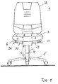
- Reference number 1 denotes an office swivel chair using the seat body according to the invention.
- the office swivel chair comprises a backrest 2, a seat 3 and a housing-like base body 8 which merges into a foot extension 4 which is preferably telescopic.
- a foot extension 4 which is preferably telescopic.
- Two cross bars 30, 31 open into the respective side area of the base body 8 and are pivotably mounted in the latter.
- the two cross bars 30, 31 form part of the rocker arm 6, which supports the backrest 2.
- a spindle 15 or 53 for setting the damping of the backrest 2 desired by the user and the pivoting position and pivoting movement of the seat 3. This will also be explained in more detail below.
- the cross member 31 is connected in a rotationally fixed manner to two lever arms, the lever arms being arranged on both sides of the housing 20 of a locking device.
- the two lever arms are provided in order to transmit the pivoting movement of the backrest 6 to a gas spring 16 in the interior of the base body 8.
- two actuating arms are provided, which on the one hand with the respective lever arm e.g. 12 are pivotally connected and act on a transverse pin 26 at their opposite end.
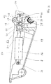
- the rear actuating arm 19 is shown in FIG. 2.
- the cross pin 26 extends transversely through a head region of the housing 24 of the gas spring 16 and through the two actuating arms and is guided in two longitudinal holes 38, 39 on the housing of the base body 8 (cf. also FIG. 4).
- the housing 20 of the locking device is connected to the base body 8 in a manner fixed against movement.
- the locking device forms a complete component, as it were.
- the housing 20 of the locking device serves as an abutment for the stamp 21 the gas spring 16.
- the construction causes that when pivoting the backrest 6, i.e. Swiveling the crossbar 30 over the lever arms e.g. 12, the operating arms e.g. 19 the housing 24 of the gas spring 16 is moved in the longitudinal direction when the plunger 21 is stationary, which enables the backrest to be pivoted gently backwards when the valve (not shown) of the gas spring 16 is open.
- the gas present in the gas spring 16 is compressed, so that the backrest automatically returns to its starting position when the load is released.
- the inclination range of the backrest 2 is normally between approximately 95 ° and 111 °.
- a longitudinally displaceable and cross-rotatable pin 47 is provided which passes through the housing 20 of the locking device and the stamp 21. Depending on the longitudinal position of the pin 47, the open or closed position of the gas spring 16 is set via the valve.
- a rotatably mounted lever arm 34 is provided, which is controlled by a cam 33 connected to a shaft 32 guided in the interior of the cross member 30.
- the handle for actuating the shaft 32 and thus the pin 47 is, as shown in FIG. 1, at the end of the associated cross member.
- the respective axial position of the pin 47 is determined by a control part 29 which has recesses 23 of different depths; 28, into which a projection 46 of a ring 48 connected to the housing 20 engages.
- the two different depths of the recesses provided in the control part ensure two different axial longitudinal positions of the pin 47.
- the inclined planes 22, for example Serrations interact with the inclined planes 27 of the control part in such a way that when the pin 47 and thus the control part 29 are axially displaced, the latter is rotated slightly, so that the projection 46 of the ring 48 when springing back, i. when the pin 47 is relieved via the lever arm 34 into the next recess e.g. 23 engages.
- the restoring force on the pin 47 is ensured by a spring or the like which is not shown in FIG. 2 for the sake of clarity.
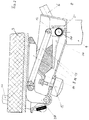
- Fig. 3 shows an embodiment of the seat support according to the invention, in which there is a synchronization between the movement of the backrest and the seat inclination.
- the seat support has a one-piece rocker arm 9, each of which is pivotably connected to the base body 8, in particular screwed, via two support arms, of which only the support arm 62 is shown in FIG. 3.
- This rocker is connected via a synchronization linkage 11 in the form of a double-articulated connecting rod to a lever arm 12 on the cross member 30. If, for example, the backrest is pivoted backwards, then the rocker arm 9 swivels slightly via the synchronization linkage 11, thereby maintaining an ergonomically favorable arrangement between the seat 3 and the backrest 2 even when the backrest 2 is pivoted backwards can be.
- FIG. 3 there is also an attenuator 13 in the form of a block of elastic material e.g. elastic polyurethane foam recognizable.
- the block 27 rests on its underside on a lever arm 34 which is connected to the cross bar 30.
- a spring plate 14 which is fastened in the region of the base body 8 facing the cross member 31, comprises the block and is held at the opposite point by means of a spindle 15 arranged on the underside of the base body 8.
- a gas spring (not shown) provided in the foot extension 4, which is also controlled via a pin 50 running in the foot extension 4.
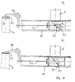
- a pivotably mounted lever arm 40 in the form of an angle is provided within the base body 8, the angle section of which is connected to a Bowden cable 42.
- the Bowden cable 42 is actuated via two inclined planes 51, 52 accommodated in the cross member 30, which lie against one another in the normal state (passive position) (FIG. 4 a)), when pivoting the inclined plane 52 with respect to the inclined plane 51 by the handle 36, however, experience a displacement such that the part of the inclined plane 52 in question, which is connected to the Bowden cable 42, is pressed outwards, as a result of which the lever arm 40 is actuated and the pin 15 moves axially. The valve is then open, so the seat height can be adjusted.
- a layer of elastic polyurethane foam is provided, which provides the necessary restoring force.
- Fig. 5 shows the arrangement of the individual components within the base body 8.
- the base body 8 is constructed like a housing and has three chambers 43, 44 and 45, which run transversely to the two spars 30, 31 and through two central struts 27; 35 are formed.
- the gas spring 16 and the locking device are located in the chamber 43 arranged on the left in FIG. 5.
- the damper 13 and the synchronization rod 11 connected to the rocker 9, not shown, are located in the chamber 45 arranged on the right.
- the lever arm 40 of the seat height adjustment mechanism is arranged, which via a disk-shaped part 41 made of elastic material, e.g. elastic polyurethane foam acts on the pin to open or close the gas spring housed in the foot extension.
- elastic material e.g. elastic polyurethane foam
- a holding part 54 is screwed to the backrest 2 according to FIG. 6.
- the holding part 54 comprises two laterally arranged Projections 55, which partially enclose the rocker 6. For the sake of clarity, only one side of the holding part 54 is provided with the reference number 55.
- the backrest 2 is pushed together with the holding part 54 onto the rocker arm 6, which tapers upwards and is secured via a snap connection 56.
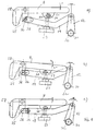
- Fig. 7 shows two positions of an embodiment of the seat support, in which the rocker 9 of the seat is rigid.
- the actuating arm 19 is consequently pulled forward, this movement being transmitted to the housing of the gas spring 16 via the cross bolt 26.
- the guidance takes place via the transverse bolt 26, which is arranged to be longitudinally displaceable within the two elongated holes 38, 39.
- the backrest and the seat are not synchronized in this embodiment.
- FIG. 8 shows the configuration of the seat support using the synchronization linkage 11. If the backrest is pivoted backwards from its basic position according to FIG. 8 a), the synchronization linkage 11 causes the rocker 9 for the seat 2 to pivot slightly (FIG. 8 b). ) in a range from -1 ° to 6 ° based on the horizontal. At the same time, the synchronization also means that when the seat is loaded, i.e. the swing arm 9 a slight pivoting caused by this is transmitted to the swing arm 6 and thus to the backrest 2.
- FIG. 9 shows a further embodiment of the seat support according to the invention, in which the seat inclination can additionally be adjusted by hand using a spindle 53.
- the synchronization of the movement of the rocker 9 of the seat with the movement of the rocker 6 of the backrest 2 takes place via two inclined cam surfaces of the rocker 9, which rest on the top of the cross pin 26.
- the cam surface 25 is shown in Fig. 9.
- the cam surfaces alone synchronize the movement from the backrest to the seat. This is because the backrest is pivoted backwards, the housing of the gas spring being pulled forward via the two actuating arms and the transverse bolt, so that the rocker arm swings slightly for the seat.
- a holding part 61 is provided on the underside of the rocker 9, which serves as an abutment for a spindle 53 provided on the underside of the base body 8.
- the spindle is held in the holding part via a cross pin 60, which is positioned within a longitudinal hole 59.
Abstract
Description
Die vorliegende Erfindung betrifft einen Sitzträger für Sitzmöbel nach dem Oberbegriff des Anspruchs 1 sowie ein Sitzmöbel unter Verwendung des erfindungsgemäßen Sitzträgers.The present invention relates to a seat support for seating furniture according to the preamble of
Die Aufgabe der vorliegenden Erfindung besteht darin, einen Sitzträger für Sitzmöbel zur Verfügung zu stellen, welcher eine einfache, fertigungstechnisch günstige Konstruktion ermöglicht sowie eine hohe Bedienungsfreundlichkeit und Zuverlässigkeit aufweist.The object of the present invention is to provide a seat support for seating furniture which enables a simple construction which is favorable in terms of production technology and which is highly user-friendly and reliable.
Diese Aufagbe wird beim gattungsgemäßen Sitzträger durch die Kombination der Merkmale des kennzeichnenden Teils gelöst. Im Gegensatz zu bekannten Konstruktionen des Standes der Technik wie etwa der Lamellenkonstruktion gemä DE-PS 30 30 009 besitzt die Erfindung zur Rückenlehnenverstellung lediglich ein Dämpfungsglied insbesondere eine Gasfeder, die mit einer als komplette Baueinheit vorgesehenen Arretiereinrichtung zusammenwirkt. Die Gasfeder weist in üblicherweise ein Ventil auf, welches von der Arretiereinrichtung ansteuerbar ist, wobei die Arretiereinrichtung vom Benutzer über ein Betätigungsteil, insbesondere über einen Handgriff einstellbar ist. Hierdurch können die notwendigen Teile des gattungsgemäßen Sitzträgers im Vergleich zu bisher bekannten Lösungen erheblich verringert werden.This task is solved in the generic seat carrier by the combination of the features of the characterizing part. In contrast to known constructions of the prior art, such as the slat construction according to DE-PS 30 30 009, the invention has only one damping member for backrest adjustment, in particular a gas spring, which interacts with a locking device provided as a complete structural unit. The gas spring usually has a valve which can be actuated by the locking device, the locking device being adjustable by the user via an actuating part, in particular via a handle. As a result, the necessary parts of the generic seat carrier can be significantly reduced compared to previously known solutions.
Gemäß Anspruch 2 ist vorgesehen, daß die Beaufschlagung der Gasfeder über einen längsverschieblichen Stift der Arretiereinrichtung erfolgt, wodurch die Möglichkeit geschaffen wird, die Arretiereinrichtung einfach anzusteuern, nämlich so, daß lediglich eine Längsverschiebung des Stifts notwendig ist. Die Ausgestaltung der Ansprüche 3 und 4 haben den Vorteil, daß die Ansteuerung des Stifts lediglich durch Druckbeaufschlagung an dessen freien Ende erfolgt, wobei die Arretierung - gleichsam wie bei einem Kugelschreiber - bei jeder Druckbeaufschlagung des Stifts sich ändert. Die Konstruktion bewirkt, daß der Benutzer den Handgriff lediglich immer in der gleichen Weise betätigen muß, um die Rückenlehne zu ent- oder verriegeln.According to claim 2 it is provided that the action of the gas spring is carried out via a longitudinally displaceable pin of the locking device, which creates the possibility to easily control the locking device, namely so that only a longitudinal displacement of the pin necessary is. The embodiment of
Der Gegenstand des Anspruchs 5 hat den Vorteil, daß sämtliche mit dem Handgriff in Verbindung stehende, die Drehbewegung übertragende Teile von außen nicht sichtbar sind, da sie im Querholm verlaufen. Daneben besteht ein wirksamer Schutz dieser Teile vor Verschmutzung. Schließlich wird die Verletzungsgefahr durch Vermeidung von an der Unterseite der Sitzfläche vorragender Teile vermindert.The object of claim 5 has the advantage that all parts connected to the handle and transmitting the rotary movement are not visible from the outside, since they run in the cross member. In addition, these parts are effectively protected against contamination. Finally, the risk of injury is reduced by avoiding parts protruding from the underside of the seat.
Der Grundkörper ist vorzugsweise gehäuseartig ausgebildet, wobei die Gasfeder sowie deren Arretierung innerhalb des Grundkörpers angeordnet sind.The base body is preferably designed like a housing, the gas spring and its locking means being arranged within the base body.
Gemäß Anspruch 6 ist der Grundkörper unter Zwischenschaltung einer Schwinge mit dem Sitz verbunden, was den Vorteil mit sich bringt, daß unterschiedliche Schwingen montierbar sind, wodurch beispielsweise bei Synchronisation der Bewegung der Rückenlehne sowie der Bewegung der Schwinge des Sitzes unterschiedliche Synchronisationswinkel je nach Kundenbedarf erzielbar sind.According to
Um bei einer Verschwenkung der Rückenlehne nach hinten eine komfortable Sitzposition beizuhalten, ist erfindungsgemäß vorgesehen, daß sich die Neigung der Schwinge mit der Neigung der Schwinge für die Rückenlehne ändert, und zwar derart, daß der hintere Bereich des Sitzes, welcher unmittelbar an die Rückenlehne angrenzt leicht nach unten verschwenkt. Hierdurch wird eine ergonomisch günstige Positionierung der Rückenlehne und des Sitzes beibehalten.In order to maintain a comfortable sitting position when pivoting the backrest to the rear, it is provided according to the invention that the inclination of the rocker changes with the inclination of the rocker for the backrest, in such a way that the rear region of the seat, which directly adjoins the backrest pivoted slightly downwards. This maintains an ergonomically favorable positioning of the backrest and seat.
Konstruktionstechnisch vorteilhaft ist es, wenn das Gehäuse der Gasfeder im Grundkörper längsbeweglich angeordnet ist. Hierbei kann der Stempel der Gasfeder als feststehendes Teil beispielsweise an der Arretiervorrichtung angreifen, die als Widerlager dient. Bei letzterer Ausgestaltung läßt sich darüber hinaus eine Synchronisation der Bewegung der Rückenlehne zur Schwinge des Sitzes dadurch erzielen, daß die Schwinge über mindestens eine schräg oder gekrümmt verlaufendes Nockenteil an einem Befestigungsteil des Gehäuses der Gasfeder angreift. Die Nockenfläche ist dabei so ausgebildet, daß bei Verschwenkung der Schwinge der Rückenlehne nach hinten aufgrund der Bewegung des Gehäuses der Gasfeder bzw. dessen Befestigungsteil die Schwinge für den Sitz an der der Rückenlehne zugewandten Seite nach unten schwenkt.It is structurally advantageous if the housing of the gas spring is arranged to be longitudinally movable in the base body. Here, the plunger of the gas spring can act as a fixed part, for example on the locking device, which serves as an abutment. In the latter embodiment, a synchronization of the movement of the backrest to the rocker of the seat can also be achieved in that the rocker engages on a fastening part of the housing of the gas spring via at least one inclined or curved cam part. The cam surface is designed such that when the rocker arm of the backrest is pivoted backwards, due to the movement of the housing of the gas spring or its fastening part, the rocker arm swings downward on the side facing the backrest.
Sofern - gemäß einer weiteren Ausgestaltung des erfindungsgemäßen Sitzträgers nach Anspruch 10 - die Schwinge mit einer Einstelleinrichtung insbesondere einer Spindel zur beliebigen Verstellung der Sitzneigung ausgestattet ist, kann durch Einstellung der Einstelleinrichtung bzw. Spindel der Verschwenkbereich der Rückenlehne verändert, d.h. verkleinert werden. Über die Nockenfläche der Schwinge wird die durch die Spindel aufgebrachte Kraft auf das Befestigungsteil der Gasfeder übertragen und führt dazu, daß etwas aus ihrer Entlage längsverschoben wird, wodurch sich der Hub der Gasfeder verringert.If - according to a further embodiment of the seat support according to the invention according to claim 10 - the rocker is equipped with an adjustment device, in particular a spindle for any adjustment of the seat inclination, the pivoting range of the backrest can be changed by adjusting the adjustment device or spindle, i.e. be made smaller. The force exerted by the spindle is transmitted to the fastening part of the gas spring via the cam surface of the rocker and causes something to be displaced longitudinally from its rest, which reduces the stroke of the gas spring.
Der Gegenstand des Anspruchs 11 ist in konstruktiver Hinsicht besonders einfach, da der Querbolzen als Befestigungsteil des Gehäuses der Gasfeder zum einem die Führung der Gasfeder innerhalb des Grundkörpers gewährleistet, zum anderen die Aufnahme für die Nockenfläche der Schwinge für den Sitz bildet.The object of
Eine gemeinsame Bewegung von Schwinge der Rückenlehne zur Schwinge des Sitzes läßt sich auch dadurch erzielen, daß die Schwinge des Sitzes über ein beidseitig drehbar gelagertes Synchronisationsgestänge mit dem Querholm und einem daran fest angeordneten Hebelarm miteinander verbunden sind. Das Synchronisationsgestänge überträgt damit die Drehbewegung des Querholms und damit der Schwinge der Rückenlehne auf die Schwinge des Sitzes.A common movement from the swing arm to the backrest Swing arm of the seat can also be achieved in that the rocker arm of the seat is connected to one another via a synchronization linkage which is rotatably mounted on both sides with the cross bar and a lever arm fixedly arranged thereon. The synchronization linkage thus transmits the rotary movement of the crossbar and thus the swing arm of the backrest to the swing arm of the seat.
Eine weitere Ausgestaltung der Erfindung, insbesondere für ein Standard-Sitzträgermodell gedacht, ist dadurch gekennzeichnet, daß die Schwinge bewegungsfest mit dem Grundkörper verbunden ist, so daß eine Bewegung auch bei Bewegung der Rückenlehne nicht erfolgt.A further embodiment of the invention, in particular intended for a standard seat support model, is characterized in that the rocker arm is connected to the base body so that it does not move, so that there is no movement even when the backrest is moved.
Erfindungsgemäß ist ein zusätzliches Dämpfglied zur Dämpfung der Bewegung der Rückenlehne vorgesehen und zwar um eine wirksame Dämpfung auch bei Personen mit hohem Körpergewicht zu gewährleisten.According to the invention, an additional damping element is provided for damping the movement of the backrest, to ensure effective damping even for people with a high body weight.
Das Dämpfungsglied ist zweckmäßigerweise so ausgelegt, daß bei Zurückschwenkung der Schwinge der Rückenlehne das Dämpfungsglied zusammengedrückt wird.The damping element is expediently designed so that when the rocker arm of the backrest is pivoted back, the damping element is compressed.
Der Gegenstand des Anspruchs 16 beschreibt eine konstruktiv sehr einfache Ausgestaltung des Dämpfungsglieds, welche in einfacher Weise montiert werden kann und darüber hinaus aus wenigen Teilen besteht.The subject matter of
Die Dämpfwirkung des Dämpfungsglieds ist ferner je nach Gewicht des Benutzers einstellbar.The damping effect of the attenuator is also adjustable depending on the weight of the user.
Der Gegenstand des Anspruchs 18 bietet eine sehr einfache Möglichkeit der konstruktiven Verwirklichung des Dämpfungsglieds. Daneben ist auch die Montage besonders einfach.The subject matter of claim 18 offers a very simple possibility of constructively realizing the attenuator. In addition, assembly is particularly easy.
Die Unteransprüche 20 - 24 betreffen zweckmäßige Ausgestaltungen der Sitzhöhenverstellung, wobei diese ebenfalls so vorgesehen ist, daß sämtliche vom Handgriff an der Außenseite des Querholms ausgehende Übertragungsteile innerhalb des Querholms verlaufen und damit von außen nicht sichtbar sind. Der zur Kraftübertragung vorgesehene Bowdenzug wird in seiner Längserstreckung über handgriffseitige schiefe Ebenen, die gegeneinander verdreht werden, verändert. Die Verwendung zweier schiefen Ebenen, die gegeneinander verdrehbar sind, hat den Vorteil, daß diese Teile ebenfalls innerhalb des Querholms unterzubringen sind.The subclaims 20-24 relate to expedient configurations of the seat height adjustment, which also applies in this way it is provided that all transmission parts starting from the handle on the outside of the crossbar run inside the crossbar and are therefore not visible from the outside. The Bowden cable intended for power transmission is changed in its longitudinal extent via inclined planes on the handle side, which are rotated relative to one another. The use of two inclined planes which can be rotated relative to one another has the advantage that these parts can also be accommodated within the cross member.
Der Gegenstand des Anspruchs 23 bietet eine besonders einfache Möglichkeit, eine Rückstellkraft des Sitzhöhenverstell-Mechanismus zu gewährleisten.The subject matter of
Zweckmäßigerweise ist der Grundkörper wie ein Gehäuse ausgestaltet, wobei Gasfeder, Arretiereinrichtung, Dämpfglied sowie Sitzhöhenverstell-Mechanismus zum größten Teil innerhalb des Grundkörpers angeordnet und daher von außen nicht zugänglich bzw. nicht sichtbar sind. Lediglich die von den beidseitig an den Querholmen angeordneten Handgriffen ausgehenden übertragenden Teile befinden sich innerhalb der betreffenden Querholme, wodurch eine sehr kompakte Bauweise geschaffen wird. Der Grundkörper ist modulartig als einheitliches Teil ausgelegt, damit die Möglichkeit besteht, den Sitzträger für verschiedene Stuhltypen verwenden zu können. Hierbei sind lediglich geringfügige Umbau- oder Anpassungsmaßnahmen notwendig.The base body is expediently designed like a housing, the gas spring, locking device, damping element and seat height adjustment mechanism being arranged for the most part within the base body and therefore not accessible or not visible from the outside. Only the transmitting parts starting from the handles arranged on both sides of the crossbars are located within the crossbars in question, which creates a very compact design. The basic body is designed as a module as a unitary part, so that there is the possibility of using the seat support for different chair types. Only minor modifications or adjustments are necessary.
Zweckmäßigerweise kann der Grundkörper zur Unterbringung der einzelnen Teile mehrere quer zu den beiden Querholmen verlaufende Kammern aufweisen. Hierdurch ergeben sich montagetechnische Vorteile, beispielsweise die seitliche Führung des Befestigungselements der Gasfeder.Appropriately, the base body for accommodating the individual parts can have a plurality of chambers running transversely to the two cross bars. This results in advantages in terms of assembly, for example the lateral guidance of the fastening element of the gas spring.
Um eine einfache auch vom Kunden durchzuführende Verbindung der Rückenlehne mit der Schwinge vornehmen zu können, ist die Verbindung von Schwinge und Rückenlehne über ein formschlüssig auf die Schwinge aufschiebbares Halteteil vorgesehen, welches an der Rückenlehne befestigt ist. Da die Schwinge der Rückenlehne nach obenhin spitz zuläuft, kann bei analoger Ausbildung des Halteteils dieses nach unten auf die Schwinge aufgeschoben werden.In order to be able to carry out a simple connection of the backrest to the swing arm, which is also to be carried out by the customer, the connection between the swing arm and the backrest is form-fitting on the rocker slide-on holding part is provided, which is attached to the backrest. Since the swing arm of the backrest tapers towards the top, the holding part can be pushed downward onto the swing arm if the holding part is designed analogously.
Zur Verbindung der Teile ist zweckmäßigerweise eine Vorrichtung zur Schnellverrastung vorgesehen.A device for quick locking is expediently provided for connecting the parts.
Die Erfindung betrifft im übrigen auch ein Sitzmöbel mit einer Sitzfläche, einer Rückenlehne, einem Fußfortsatz sowie einem Fußgestell unter Verwendung des erfindungsgemäßen Sitzträgers gemäß mindestens einem der Ansprüche 1 - 27.The invention also relates to seating furniture with a seat, a backrest, a foot extension and a foot frame using the seat support according to the invention according to at least one of claims 1-27.
Nachstehend werden verschiedene Ausgestaltungen der vorliegenden Erfindung anhand der Zeichnungen näher erläutert. Es zeigen:
- Fig. 1
- einen Bürodrehstuhl unter Verwendung des erfindungsgemäßen Sitzträgers in Vorderansicht;
- Fig. 2
- eine Teilschnittdarstellung des Grundkörpers entlang der Schnittlinie I - I in Fig. 1 in Blickrichtung A;
- Fig. 3
- eine Teilschnittdarstellung des Grundkörpers entlang der Schnittlinie II - II in Fig. 1 in Blickrichtung B;
- Fig. 4
- das Prinzip der Sitzhöhenverstellung in der Ausgangsstellung (a) sowie in der Stellung während der die Höhenverstellung erfolgt (b);
- Fig. 5
- eine Draufsicht auf den Innenteil des Grundkörpers;
- Fig. 6
- eine Rückansicht des Bürodrehstuhls gemäß Fig. 1 in stark vereinfachter Darstellungsweise;
- Fig. 7
- je eine Teildarstellung der Schwinge für den Sitz sowie des Querholms der Rückenlehne einschließlich des Betätigungsarms in Ausgangsstellung (a) sowie in verschwenkter Stellung (b), wobei die Schwinge für den Sitz hierbei starr ausgebildet ist;
- Fig. 8
- zeigt eine Möglichkeit der synchronisierten Bewegung der Schwinge der Rückenlehne und der Schwinge für den Sitz in Ausgangsstellung (a) sowie verschwenkter Stellung (b) und
- Fig. 9
- eine Ausgestaltung zur synchronen Bewegung der beiden Schwingen zueinander unter Verwendung einer zusätzlichen Einstelleinrichtung in verschiedenen Stellungen (a - c).
- Fig. 1
- an office swivel chair using the seat support according to the invention in front view;
- Fig. 2
- a partial sectional view of the base body along the section line I - I in Figure 1 in viewing direction A;
- Fig. 3
- a partial sectional view of the base body along the section line II - II in Figure 1 in viewing direction B;
- Fig. 4
- the principle of the seat height adjustment in the starting position (a) and in the position during which the height adjustment takes place (b);
- Fig. 5
- a plan view of the inner part of the base body;
- Fig. 6
- a rear view of the office swivel chair according to Figure 1 in a greatly simplified representation.
- Fig. 7
- a partial representation of the rocker for the seat and the crossbar of the backrest including the actuating arm in the starting position (a) and in the pivoted position (b), the rocker for the seat being rigid;
- Fig. 8
- shows a possibility of synchronized movement of the rocker of the backrest and the rocker for the seat in the starting position (a) and pivoted position (b) and
- Fig. 9
- an embodiment for the synchronous movement of the two rockers to each other using an additional setting device in different positions (a - c).
Bezugsziffer 1 kennzeichnet einen Bürodrehstuhl unter Verwendung des erfindungsgemäßen Sitzkörpers. Der Bürodrehstuhl umfaßt eine Rückenlehne 2, einen Sitz 3 sowie einen gehäuseartigen Grundkörper 8, welcher in einen vorzugsweise teleskopartig ausgebildeten Fußfortsatz 4 übergeht. An der Unterseite des Fußfortsatzes 4 befindet sich ein Fußkreuz 5.
Zwei Querholme 30, 31 münden in den jeweiligen Seitenbereich des Grundkörpers 8 und sind in letzterem schwenkbar gelagert. Die beiden Querholme 30, 31 bilden einen Bestandteil der Schwinge 6, die die Rückenlehne 2 trägt. An der jeweiligen Stirnseite der beiden Querholme 30, 31 befindet sich je ein Handgriff 36, 37, welcher - wie im einzelnen später erläutert werden wird - jeweils für die Verstellung der Rückenlehnenbeweglichkeit sowie für die Höhenverstellung des Sitzes vorgesehen ist.Two cross bars 30, 31 open into the respective side area of the
An der Unterseite des Grundkörpers 8 befindet sich eine Spindel 15 bzw. 53 zur Einstellung der vom Benutzer jeweils gewünschten Dämpfung der Rückenlehne 2 sowie der Schwenkstellung und Schwenkbewegung des Sitzes 3. Auch dies wird nachstehend noch näher erläutert werden.On the underside of the
Aus Fig. 2 wird die Ansteuerung und Verstellmöglichkeit der Rückenlehne deutlich. Wie aus Fig. 1 bereits ersichtlich ist, steht die Schwinge 6 der Rückenlehne mit dem jeweiligen Querholm 31 in Verbindung, von denen der Querholm 30 in Fig. 2 dargestellt ist. Beide Querholme 30, 31 sind im Inneren des Grundkörpers 8 drehbar gelagert.From Fig. 2, the control and adjustment of the backrest is clear. As can already be seen from FIG. 1, the
Der Querholm 31 ist mit zwei Hebelarmen drehfest verbunden, wobei die Hebelarme beidseitig des Gehäuses 20 einer Arretiereinrichtung angeordnet sind. Der Übersichtlichkeit halber ist in Fig. 2 lediglich der hintere Hebelarm 12 dargestellt. Die beiden Hebelarme sind vorgesehen, um die Schwenkbewegung der Rückenlehne 6 auf eine Gasfeder 16 im Inneren des Grundkörpers 8 zu übertragen. Hierzu sind zwei Betätigungsarme vorgesehen, welche zum einen mit dem jeweiligen Hebelarm z.B. 12 verschwenkbar verbunden sind und an ihrem entgegengesetzten Ende an einem Querbolzen 26 angreifen. In Fig. 2 ist der Übersichtlichkeit halber lediglich der hintere Betätigungsarm 19 dargestellt.The
Der Querbolzen 26 verläuft quer durch einen Kopfbereich des Gehäuses 24 der Gasfeder 16 sowie durch die beiden Betätigungsarme und ist in zwei Längslöchern 38, 39 am Gehäuse des Grundkörpers 8 geführt (vgl. auch Fig. 4).The
Das Gehäuse 20 der Arretiereinrichtung ist bewegungsfest mit dem Grundkörper 8 verbunden. Die Arretiereinrichtung bildet gleichsam ein komplettes Bauteil. Das Gehäuse 20 der Arretiereinrichtung dient als Widerlager für den Stempel 21 der Gasfeder 16.The
Die Konstruktion bewirkt, daß bei Verschwenkung der Rückenlehne 6, d.h. Verschwenkung des Querholms 30 über die Hebelarme z.B. 12, die Betätigungsarme z.B. 19 das Gehäuse 24 der Gasfeder 16 bei feststehendem Stempel 21 in Längsrichtung bewegt wird, wodurch ein weiches nach hinten Verschwenken der Rückenlehne ermöglicht wird, wenn das (nicht dargestellte) Ventil der Gasfeder 16 geöffnet ist. Beim nach hinten Verschwenken der Rückenlehne wird das in der Gasfeder 16 vorhandene Gas komprimiert, so daß bei Entlastung die Rückenlehne automatisch in ihre Ausgangsstellung zurückgeht. Der Neigungsbereich der Rückenlehne 2 liegt im Normalfall zwischen ca. 95° und 111°.The construction causes that when pivoting the
Zur Betätigung des Ventils der Gasfeder 16 ist ein längsverschiebbar und querverdrehbarer Stift 47 vorgesehen, welcher das Gehäuse 20 der Arretiereinrichtung sowie den Stempel 21 durchsetzt. Je nach Längsposition des Stifts 47 wird über das Ventil die offene oder geschlossene Stellung der Gasfeder 16 eingestellt.To actuate the valve of the
Zur Betätigung des Stifts 47 ist ein drehbar gelagerter Hebelarm 34 vorgesehen, welcher von einem mit einer im Inneren des Querholms 30 geführten Welle 32 verbundenen Nocken 33 angesteuert wird. Der Handgriff zur Betätigung der Welle 32 und damit des Stifts 47 befindet sich wie aus Fig. 1 ersichtlich, am Ende des zugehörigen Querholms.To actuate the
Die Festlegung der jeweiligen Axialposition des Stifts 47 erfolgt durch ein Steuerteil 29, welches unterschiedlich tiefe Ausnehmungen 23; 28 aufweist, in die ein Vorsprung 46 eines mit dem Gehäuse 20 verbundenen Kranzes 48 eingreift. Die beiden unterschiedlichen Tiefen der im Steuerteil vorgesehenen Ausnehmungen gewährleisten zwei unterschiedliche axiale Längspositionen des Stifts 47.The respective axial position of the
Damit bei jeder Betätigung des Stifts 47 über den Hebelarm 34, somit bei jeder Drehung des Handgriffs 37 jeweils eine im Vergleich zur vorhergehenden unterschiedliche axiale Position arretiert wird, ist an der Rückseite des Steuerteils, ebenfalls in fester Verbindung mit dem Gehäuse 20 der Arretiereinrichtung ein weiterer Kranz 62 vorgesehen, dessen schiefe Ebenen 22 z.B. Zacken mit den schiefen Ebenen 27 des Steuerteils derart zusammenwirken, daß bei axialer Verschiebung des Stifts 47 und damit des Steuerteils 29 letzteres geringfügig gedreht wird, so daß der Vorsprung 46 des Kranzes 48 beim Zurückfedern, d.h. bei Entlastung des Stifts 47 über den Hebelarm 34 in die nächste Ausnehmung z.B. 23 eingreift.So that each time the
Die Rückstellkraft auf den Stift 47 wird durch eine in Fig. 2 der Übersichtlichkeit halber nicht dargestellte Feder oder dgl. gewährleistet.The restoring force on the
Fig. 3 zeigt eine Ausgestaltung des erfindungsgemäßen Sitzträgers, bei dem eine Synchronisation zwischen der Bewegung der Rückenlehne und der Sitzneigung erfolgt.Fig. 3 shows an embodiment of the seat support according to the invention, in which there is a synchronization between the movement of the backrest and the seat inclination.
Zur Befestigung des Sitzes 3 weist der Sitzträger eine einstückige Schwinge 9 auf, die jeweils über zwei Stützarme, von denen lediglich der Stützarm 62 in Fig. 3 dargestellt ist, verschwenkbar mit dem Grundkörper 8 verbunden, insbesondere verschraubt ist.To fasten the
Diese Schwinge steht über ein Synchronisationsgestänge 11 in Form einer doppelgelenkig gelagerten Verbindungsstange mit einem Hebelarm 12 am Querholm 30 in Verbindung. Wird nun beispielsweise die Rückenlehne nach hinten verschwenkt, so erfolgt über das Synchronisationsgestänge 11 eine geringfügige Abschwenkung der Schwinge 9, wodurch eine ergonomisch günstige Anordnung zwischen Sitz 3 und Rückenlehne 2 auch bei nach hinten verschwenkter Rückenlehne 2 beibehalten werden kann.This rocker is connected via a
Aus Fig. 3 ist weiterhin ein Dämpfglied 13 in Form eines Blocks aus elastischem Material z.B. elastischem Polyurethanschaum erkennbar. Der Block 27 liegt an dessen Unterseite auf einem Hebelarm 34 auf, der mit dem Querholm 30 in Verbindung steht. An der Oberseite befindet sich ein Federblech 14, welches in dem Querholm 31 zugewandten Bereich des Grundkörpers 8 befestigt ist, den Block umfaßt und an der gegenüberliegenden Stelle mittels einer an der Unterseite des Grundkörpers 8 angeordneten Spindel 15 gehalten ist.From Fig. 3 there is also an
Bei Zurückschwingen der Schwinge 6 wird der Hebelarm 34 nach oben gedrückt, wodurch eine Kompression des Dämpfglieds 13 erfolgt und die Zurückbewegung der Rückenlehne 2 bzw. deren Schwinge 6 dadurch gedämpft wird.When the
Zur Einstellung der Dämpfwirkung bei Personen unterschiedlichen Gewichts ist es lediglich erforderlich, die an der Unterseite des Grundkörpers 8 befindliche Spindel 15 zu betätigen. Durch Festziehen der Spindel 15 kann die Dämpfwirkung durch Kompression des Blocks 27 erhöht und bei Lockerung der Spindel entsprechend reduziert werden.To set the damping effect for people of different weights, it is only necessary to actuate the
Die Verstellung der Sitzhöhe erfolgt gemäß Fig. 4 ebenfalls über eine in der Fußverlängerung 4 vorgesehene Gasfeder (nicht dargestellt), die ebenfalls über einen im Fußfortsatz 4 verlaufenden Stift 50 eingesteuert wird. Zu diesem Zweck ist innerhalb des Grundkörpers 8 ein verschwenkbar gelagerter Hebelarm 40 in Form eines Winkels vorgesehen, dessen ein Winkelabschnitt mit einem Bowdenzug 42 in Verbindung steht.4 is also adjusted via a gas spring (not shown) provided in the
Die Betätigung des Bowdenzugs 42 erfolgt über zwei im Querholm 30 untergebrachten schiefe Ebenen 51, 52, die im Normalzustand (Passivstellung) aneinanderliegen (Fig.4 a)), bei Verschwenkung der schiefen Ebene 52 gegenüber der schiefen Ebene 51 durch den Handgriff 36 jedoch eine Verschiebung derart erfahren, daß das betreffende Teil der schiefen Ebene 52, welches mit dem Bowdenzug 42 in Verbindung steht nach außen gedrückt wird, wodurch der Hebelarm 40 betätigt wird und den Stift 15 axial bewegt. Das Ventil ist dann geöffnet, die Sitzhöhe kann somit verstellt werden.The
An der Oberseite des Fußfortsatzes 4 und zwar vorzugsweise zwischen Hebelarm 40 und Stift 50 ist eine Schicht aus elastischem Polyurethanschaum vorgesehen, die für die nötige Rückstellkraft sorgt.On the top of the
Fig. 5 zeigt die Anordnung der einzelnen Komponenten innerhalb des Grundkörpers 8. Der Grundkörpers 8 ist gehäuseartig aufgebaut und weist drei Kammern 43, 44 sowie 45 auf, die quer zu den beiden Holmen 30, 31 verlaufen und durch zwei Mittelstreben 27; 35 gebildet werden.Fig. 5 shows the arrangement of the individual components within the
In der in Fig. 5 links angeordneten Kammer 43 befindet sich die Gasfeder 16 und die Arretiereinrichtung.The
In der rechts angeordneten Kammer 45 befindet sich das Dämpfglied 13 sowie die mit der nicht dargestellten Schwinge 9 verbundenen Synchronisationsstange 11.The
In der mittleren Kammer 44, die zum Teil nach unten hin offen ausgestaltet ist, ist der Hebelarm 40 des Sitzhöhenverstell-Mechanismus angeordnet, welcher über ein scheibenförmiges Teil 41 aus elastischem Material, z.B. elastischem Polyurethanschaum den Stift zum Öffnen oder zum Schließen der im Fußfortsatz untergebrachten Gasfeder beaufschlagt.In the
Zur Verbindung der Rückenlehne 2 mit der Schwinge 6 ist gemäß Fig. 6 ein Halteteil 54 fest mit der Rückenlehne 2 verschraubt. Das Halteteil 54 umfaßt zwei seitlich angeordnete Vorsprünge 55, die die Schwinge 6 zum Teil umfaßen. Der Übersichtlichkeit halber ist lediglich eine Seite des Halteteils 54 mit dem Bezugszeichen 55 versehen. Die Rückenlehne 2 wird zusammen mit dem Halteteil 54 auf die nach oben hin sich verjüngende Schwinge 6 aufgeschoben und über eine Schnappverbindung 56 gesichert.To connect the backrest 2 to the
Fig. 7 zeigt zwei Stellungen einer Ausgestaltung des Sitzträgers, bei dem die Schwinge 9 des Sitzes starr ausgebildet ist. Bei Bewegung der Rückenlehne wird folglich der Betätigungsarm 19 nach vorn gezogen, wobei diese Bewegung über den Querbolzen 26 auf das Gehäuse der Gasfeder 16 übertragen wird. Die Führung erfolgt über den Querbolzen 26, welcher innerhalb der beiden Langlöcher 38, 39 längsverschieblich angeordnet ist. Eine Synchronisation der Rückenlehne un des Sitzes erfolgt bei dieser Ausgestaltung nicht.Fig. 7 shows two positions of an embodiment of the seat support, in which the
Fig. 8 zeigt die Ausgestaltung des Sitzträgers unter Verwendung des Synchronisationsgestänges 11. Wird die Rückenlehne aus ihrer Grundstellung gemäß Fig. 8 a) nach hinten verschwenkt, bewirkt das Synchronisationsgestänge 11 ein leichtes Abschwenken der Schwinge 9 für den Sitz 2 (Fig. 8 b)) in einen Bereich von -1° bis 6° bezogen auf die Waagerechte. Die Synchronisation bewirkt gleichzeitig auch, daß bei Belastung des Sitzes, d.h. der Schwinge 9 eine dadurch bedingte geringfügige Verschwenkung auf die Schwinge 6 und damit auf die Rückenlehne 2 übertragen wird.8 shows the configuration of the seat support using the
Fig. 9 zeigt eine weitere Ausgestaltung des erfindungsgemäßen Sitzträgers, bei dem die Sitzneigung zusätzlich per Hand über eine Spindel 53 verstellt werden kann. Die Synchronisierung der Bewegung der Schwinge 9 des Sitzes mit der Bewegung der Schwinge 6 der Rückenlehne 2erfolgt über zwei schräg verlaufende Nockenflächen der Schwinge 9, die auf der Oberseite des Querbolzen 26 aufliegen. Der Übersichtlichkeit halber ist lediglich die Nockenfläche 25 in Fig. 9 wiedergegeben.FIG. 9 shows a further embodiment of the seat support according to the invention, in which the seat inclination can additionally be adjusted by hand using a
Zum einen bewirken die Nockenflächen allein eine Synchronisation der Bewegung von Rückenlehne zu Sitz. Wird nämlich die Rückenlehne nach hinten verschwenkt, wobei das Gehäuse der Gasfeder über die beiden Betätigungsarme sowie den Querbolzen nach vorne gezogen wird, so daß die Schwinge für den Sitz leicht abschwenkt.On the one hand, the cam surfaces alone synchronize the movement from the backrest to the seat. This is because the backrest is pivoted backwards, the housing of the gas spring being pulled forward via the two actuating arms and the transverse bolt, so that the rocker arm swings slightly for the seat.
In Fig. 9 ist an der Unterseite der Schwinge 9 ein Halteteil 61 vorgesehen, welches als Widerlager für eine an der Unterseite des Grundkörpers 8 vorgesehene Spindel 53 dient. Die Spindel wird in dem Halteteil über einen Querstift 60 gehalten, welcher innerhalb eines Längslochs 59 positioniert ist.9, a holding
Wird aus der Ausgangsstellung gemäß Fig. 9 a) heraus die Spindel 53 angezogen, wodurch die Neigung des Sitzes und der Schwinge 9 für den Sitz erhöht wird, erfolgt aufgrund der Nockenflächen, die auf den Querbolzen 26 einwirken, eine Veränderung der Neigung der Rückenlehne (vgl. Fig. 9 b)). Die Bewegung des Sitzes zur Rückenlehne erfolgt in einem Verhältnis von etwa 1 : 1,1.If the
In dieser Einstellung kann dann eine begrenzte Beweglichkeit der Rückenlehne erfolgen (Fig. 9c).A limited mobility of the backrest can then take place in this setting (FIG. 9c).
- 11
- SitzmöbelSeating
- 22nd
- Rückenlehnebackrest
- 33rd
- SitzSeat
- 44th
- FußfortsatzProcess of the foot
- 55
- FußkranzWreath
- 66
- Schwinge für RückenlehneSwing arm for backrest
- 77
- QuerstangeCrossbar
- 88th
- GrundkörperBasic body
- 99
- Schwinge für SitzSwing arm for seat
- 1010th
- HebelarmLever arm
- 1111
- SynchronisationsgestängeSynchronization linkage
- 1212th
- HebelarmLever arm
- 1313
- DämpfgliedAttenuator
- 1414
- Gegenlager (Federblech)Counter bearing (spring plate)
- 1515
- Spindelspindle
- 1616
- GasfederGas spring
- 1717th
- FührungsbuchseGuide bushing
- 1818th
- FederstangeSpring rod
- 1919th
- BetätigungsarmOperating arm
- 2020th
- Gehäuse der ArretiereinrichtungHousing of the locking device
- 2121
- Stempelstamp
- 2222
- schräge Flächesloping surface
- 2323
- AuusnehmungExemption
- 2424th
- Gehäuse der GasfederGas spring housing
- 2525th
- NockenflächeCam surface
- 2626
- QuerbolzenCross bolt
- 2727
- MittelstrebeMiddle strut
- 2828
- AusnehmungRecess
- 2929
- SteuerteilControl section
- 3030th
- QuerholmQuerholm
- 3131
- QuerholmQuerholm
- 3232
- Wellewave
- 3333
- NockeCam
- 3434
- HebelarmLever arm
- 3535
- MittelstrebeMiddle strut
- 3636
- HandgriffHandle
- 3737
- HandgriffHandle
- 3838
- LängslochLongitudinal hole
- 3939
- LängslochLongitudinal hole
- 4040
- HebelarmLever arm
- 4141
- scheibenförmiges Teildisc-shaped part
- 4242
- BowdenzugBowden cable
- 4343
- Kammerchamber
- 4444
- Kammerchamber
- 4545
- Kammerchamber
- 4646
- Vorsprunghead Start
- 4747
- Stiftpen
- 4848
- Kranzwreath
- 4949
- GegenringMating ring
- 5050
- Stift im FußfortsatzPin in the process of the foot
- 5151
- schiefe Ebeneinclined plane
- 5252
- schiefe Ebeneinclined plane
- 5353
- Spindelspindle
- 5454
- HalteteilHolding part
- 5555
- Vorsprunghead Start
- 5656
- SchnappverbindungSnap connection
- 5757
- HebelarmLever arm
- 5858
- StützarmSupport arm
- 5959
- LängslochLongitudinal hole
- 6060
- QuerstiftCross pin
- 6161
- HalteteilHolding part
- 6262
- StützarmSupport arm
Claims (28)
gekennzeichnet durch
folgende Merkmale:
marked by
following features:
dadurch gekennzeichnet,
daß die Arretiereinrichtung einen mit der Gasfeder (16) in Verbindung stehenden, längsverschieblichen Stift (47) aufweist, der in zwei axialen Positionen in Längsrichtung arretierbar ist und die beiden Positionen die jeweiligen Einstellungen der Gasfeder (16) festlegen.Seat support according to claim 1,
characterized,
that the locking device one with the gas spring (16) connected, longitudinally displaceable pin (47) which can be locked in two axial positions in the longitudinal direction and the two positions determine the respective settings of the gas spring (16).
dadurch gekennzeichnet,
daß der Stift (47) in einem Gehäuse (20) der Arretiereinrichtung verläuft, an der Außenseite des Stifts ein ringförmiges Steuerteil (29) vorgesehen ist, welches zur Gewährleistung der zu arretierenden Längsposition des Stifts (47) unterschiedlich tiefe Ausnehmungen (23; 28) aufweist, in die mindestens ein Vorsprung (46) eines fest am Gehäuse (20) der Arretiereinrichtung angeordneten Kranzes (48) eingreifen oder umgekehrt.Seat support according to claim 2,
characterized,
that the pin (47) runs in a housing (20) of the locking device, on the outside of the pin an annular control part (29) is provided which, to ensure the longitudinal position of the pin (47) to be locked, recesses (23; 28) of different depths which is engaged by at least one projection (46) of a ring (48) fixed to the housing (20) of the locking device or vice versa.
dadurch gekennzeichnet,
daß auf den Stift (47) eine Rückstellkraft wirkt und bei jeder Betätigung des Stifts (47) eine Verschwenkung desselben aufgrund des Zusammenwirkens von schiefen Ebenen erfolgt.Seat support according to claim 3,
characterized,
that a restoring force acts on the pin (47) and the same is pivoted each time the pin (47) is actuated due to the interaction of inclined planes.
dadurch gekennzeichnet,
daß die Arretiereinrichtung über einen an der Außenseite des einen Querholms (31) der Schwinge (6) angeordneten Handgriff (37) betätigbar ist, wobei die Drehbewegung des Handgriffs (31) über eine im Inneren des Querholms (31) verlaufende Welle (32), einen mit der Welle (32) fest verbundenen Nocken (33) und einen vom Nocken bewegten Hebelarm (34) auf den Stift (47) übertragen wird.Seat support according to at least one of the preceding claims,
characterized,
that the locking device is arranged on the outside of the one cross member (31) of the rocker (6) Handle (37) can be actuated, the rotary movement of the handle (31) via a shaft (32) extending inside the cross member (31), a cam (33) fixedly connected to the shaft (32) and a lever arm moved by the cam ( 34) is transferred to the pin (47).
dadurch gekennzeichnet,
daß auf dem Grundkörper (8) eine Schwinge (9) für den Sitz (3) montiert ist.Seat support according to at least one of the preceding claims,
characterized,
that a rocker (9) for the seat (3) is mounted on the base body (8).
dadurch gekennzeichnet,
daß sich die Neigung der Schwinge (9) mit der Neigung der Schwinge (6) für die Rückenlehne (2) ändert.Seat support according to claim 6,
characterized,
that the inclination of the rocker (9) changes with the inclination of the rocker (6) for the backrest (2).
dadurch gekennzeichnet,
daß das Gehäuse (24) der Gasfeder (16) im Grundkörper (8) längsbeweglich angeordnet ist. .Seat support according to claim 6 or 7,
characterized,
that the housing (24) of the gas spring (16) in the base body (8) is arranged to be longitudinally movable. .
dadurch gekennzeichnet,
daß die Schwinge (9) über mindestens eine schräg oder gekrümmt verlaufende Nockenfläche (25) an einem Befestigungsteil des Gehäuses (24) der Gasfeder (16) angreift.Seat support according to claim 8,
characterized,
that the rocker (9) on at least one inclined or curved cam surface (25) on one Fastening part of the housing (24) of the gas spring (16) engages.
dadurch gekennzeichnet,
daß die Schwinge (9) mit einer Einstelleinrichtung insbesondere Spindel (53) zur beliebigen Verstellung der Sitzneigung ausgestattet ist.Seat support according to claim 9,
characterized,
that the rocker (9) is equipped with an adjusting device, in particular a spindle (53), for any adjustment of the seat inclination.
dadurch gekennzeichnet,
daß das Befestigungsteil ein Querbolzen (26) ist, welcher, mit dem Kopf (24) der Gasfeder (16) in Verbindung steht und innerhalb zweier Längslöcher (38, 39) im Grundkörper (8) längsverschieblich geführt ist.Seat support according to at least one of claims 8-10,
characterized,
that the fastening part is a cross bolt (26) which is connected to the head (24) of the gas spring (16) and is guided so as to be longitudinally displaceable within two longitudinal holes (38, 39) in the base body (8).
dadurch gekennzeichnet,
daß die Schwinge (6) mit einem Hebelarm (z.B. 30) am Querarm (31) über ein beidseitig drehbar gelagertes Synchrongestänge (11) miteinander in Verbindung stehen.Seat support according to at least one of claims 6 - 11,
characterized,
that the rocker (6) with a lever arm (for example 30) on the cross arm (31) are connected to one another via a synchronously rotatably mounted synchronous linkage (11).
dadurch gekennzeichnet,
daß die Schwinge (9) bewegungsfest mit dem Grundkörper (8) verbunden ist und auf dem schräg ausgebildeten Abschnitt des Betätigungsarms (19) aufliegt.Seat support according to claim 7,
characterized,
that the rocker (9) is fixedly connected to the base body (8) and rests on the obliquely formed section of the actuating arm (19).
dadurch gekennzeichnet,
daß ein zusätzliches Dämpfglied (13) zur Dämpfung der Bewegung der Rückenlehne (2) vorgesehen ist.Seat support in particular according to at least one of claims 1-13,
characterized,
that an additional damping member (13) is provided to dampen the movement of the backrest (2).
dadurch gekennzeichnet,
daß das Dämpfglied (13) so ausgelegt ist, daß bei Zurückschwenkung der Schwinge (6) das Dämpfglied zusammengedrückt wird.Seat support according to claim 14,
characterized,
that the damping member (13) is designed so that when the rocker (6) is pivoted back, the damping member is compressed.
dadurch gekennzeichnet,
daß ein fest mit der Schwinge (6) in Verbindung stehender Hebelarm (12) an der Unterseite des Dämpfglieds (13) angreift und als Widerlager ein an der Oberseite des Dämpfglieds angeordnetes Halteteil (14) vorgesehen ist.Seat support according to claim 14 or 15,
characterized,
that a lever arm (12), which is firmly connected to the rocker (6), engages on the underside of the damping member (13) and a holding part (14) arranged on the top of the damping member is provided as an abutment.
dadurch gekennzeichnet,
daß die Dämpfwirkung des Dämpfglieds (13) einstellbar ist.Seat support according to claim 15 or 16,
characterized,
that the damping effect of the attenuator (13) is adjustable.
dadurch gekennzeichnet,
daß das Halteteil (14) an dessen einer Seite mit dem Grundkörper (8) schwenkbar verbunden ist, in dessen Mittelbereich eine Ausnehmung (28) vorgesehen ist, die das Dämpfglied zum Teil umschließt und das Halteteil (14) an dessen anderem Ende mit einer Spindel (15) in Verbindung steht, die je nach Spindelstellung für eine bestimmte Komprimierung des Dämpfglieds sorgt.Seat support according to claim 17,
characterized,
that the holding part (14) is pivotally connected on one side to the base body (8), in the central region of which a recess (28) is provided which partially surrounds the damping member and the holding part (14) at the other end with a spindle (15) is connected, which ensures a certain compression of the attenuator depending on the spindle position.
dadurch gekennzeichnet,
daß das Dämpfglied (13) aus einem Block aus elastischem Polyurethanschaum besteht.Seat support according to at least one of claims 15-18,
characterized,
that the attenuator (13) consists of a block of elastic polyurethane foam.
dadurch gekennzeichnet,
daß die Sitzhöhenverstellung über eine im Fußfortsatz (4) vorgesehene Gasfeder (35) erfolgt, die über einen längsverschieblichen Stift (50) geschlossen oder geöffnet werden kann, wobei die Ansteuerung über einen an der Außenseite des Querholms (31) angeordneten Handgriff (36) erfolgt, der über ein Betätigungsteil einen Hebelarm (40) bewegt, der zur Längsbewegung des Stifts (50) an diesen angreift.Seat support, in particular according to at least one of claims 1-19,
characterized,
that the seat height is adjusted via a gas spring (35) provided in the foot extension (4), which can be closed or opened via a longitudinally displaceable pin (50), the control being effected via a handle (36) arranged on the outside of the cross member (31) which moves a lever arm (40) via an actuating part, which acts on the pin (50) for longitudinal movement thereof.
dadurch gekennzeichnet,
daß der Handgriff (36) und der Hebelarm (40) über einen durch den Handgriff (36) längsbewegbaren Bowdenzug (42) in Verbindung steht.Seat support according to claim 17,
characterized,
that the handle (36) and the lever arm (40) are connected via a Bowden cable (42) which is longitudinally movable by the handle (36).
dadurch gekennzeichnet,
daß die Längsbewegung des Betätigungsteils, insbesondere Bowdenzug (42) über zwei schiefe Ebenen (51, 52) erfolgt, die innerhalb des Querholms (31) gegeneinander verdrehbar sind.Seat support according to claim 20 or 21,
characterized,
that the longitudinal movement of the actuating part, in particular Bowden cable (42) takes place over two inclined planes (51, 52) which can be rotated relative to one another within the cross member (31).
dadurch gekennzeichnet,
daß die Rückstellkraft der Sitzhöhenverstellung über ein vorzugsweise scheibenförmiges Teil (41) aus elastischem Material erfolgt, das vom Hebelarm (40) beaufschlagt wird.Seat support according to at least one of claims 20-22,
characterized,
that the restoring force of the seat height adjustment takes place via a preferably disc-shaped part (41) made of elastic material which is acted upon by the lever arm (40).
dadurch gekennzeichnet,
daß das scheibenförmige Teil (41) aus elastischem Polyurethanschaum besteht.Seat support according to claim 23,
characterized,
that the disc-shaped part (41) consists of elastic polyurethane foam.
dadurch gekennzeichnet,
daß der Grundkörper (4) als Grundmodul aufgebaut ist und mehrere längliche, quer zu den beiden Querholmen (30, 31) verlaufende Kammern (43 - 45) aufweist, die die Arretiereinrichtung für die Rückenlehne (2) einschließlich der Gasfeder (16) für die Rückenlehnenbewegung, das Dämpfglied (13) sowie den Hebelarm (40) für die Sitzhöhenverstellung beinhalten.Seat support according to at least one of the preceding claims,
characterized,
that the base body (4) is constructed as a basic module and has several elongate chambers (43 - 45) running transversely to the two cross bars (30, 31), which the locking device for the backrest (2) including the gas spring (16) for the Backrest movement, the damping element (13) and the lever arm (40) for the seat height adjustment include.
dadurch gekennzeichnet,
daß die Verbindung von Schwinge (6) und Rückenlehne (2) über ein formschlüssig auf die Schwinge (6) aufschiebbares Halteteil (54) erfolgt.Seat support according to at least one of the preceding claims,
characterized,
that the connection of rocker (6) and backrest (2) via a form-fitting on the rocker (6) slide-on holding part (54).
dadurch gekennzeichnet,
daß das Halteteil (53) mit Schnellverrastungsmittel zur Verrastung mit der Schwinge ausgestattet ist, welche an der Rückenlehne befestigt ist.Seat support according to claim 26,
characterized,
that the holding part (53) is equipped with quick locking means for locking with the rocker which is attached to the backrest.
gekennzeichnet durch
einen Sitzträger nach mindestens einem der Ansprüche 1 - 27.Office chair with a backrest, a seat, a foot in the shape of a star base and a foot extension,
marked by
a seat support according to at least one of claims 1-27.
Applications Claiming Priority (2)
| Application Number | Priority Date | Filing Date | Title |
|---|---|---|---|
| DE4235435 | 1992-10-21 | ||
| DE4235435A DE4235435A1 (en) | 1992-10-21 | 1992-10-21 | Seat supports for seating |
Publications (1)
| Publication Number | Publication Date |
|---|---|
| EP0593881A1 true EP0593881A1 (en) | 1994-04-27 |
Family
ID=6470949
Family Applications (1)
| Application Number | Title | Priority Date | Filing Date |
|---|---|---|---|
| EP93113793A Ceased EP0593881A1 (en) | 1992-10-21 | 1993-08-28 | A seat-support for sitting furniture |
Country Status (2)
| Country | Link |
|---|---|
| EP (1) | EP0593881A1 (en) |
| DE (1) | DE4235435A1 (en) |
Cited By (3)
| Publication number | Priority date | Publication date | Assignee | Title |
|---|---|---|---|---|
| KR100623831B1 (en) | 2003-11-18 | 2006-09-19 | 수스파 홀딩 게엠베하 | Adjustable-length compression spring |
| US10881208B2 (en) * | 2016-02-23 | 2021-01-05 | Kokuyo Co., Ltd. | Chair and seat support mechanism |
| CN113197456A (en) * | 2021-01-13 | 2021-08-03 | 安吉万宝智能家居科技有限公司 | Multifunctional chair |
Families Citing this family (1)
| Publication number | Priority date | Publication date | Assignee | Title |
|---|---|---|---|---|
| DE202017100480U1 (en) * | 2017-01-30 | 2018-05-03 | Armin Sander | Seating furniture, in particular office chair |
Citations (6)
| Publication number | Priority date | Publication date | Assignee | Title |
|---|---|---|---|---|
| FR1298474A (en) * | 1961-05-20 | 1962-07-13 | Advanced seat | |
| DE2925520A1 (en) * | 1979-06-25 | 1981-01-15 | Mauser Waldeck Gmbh | Swivel chair with adjustable tilt and height - has support column, arm, and sprung telescoping pistons |
| EP0052832A2 (en) * | 1980-11-21 | 1982-06-02 | Protoned B.V. | Control-head for pneumatic springs, particularly for adjusting seats of sitting furniture |
| EP0126839A1 (en) * | 1983-05-10 | 1984-12-05 | Meiko Industrial Co., Ltd. | Reclining chair |
| EP0263323A2 (en) * | 1986-10-07 | 1988-04-13 | Inaba Seisakusho Co., Ltd. | Sitting furniture |
| EP0283170A1 (en) * | 1987-03-14 | 1988-09-21 | PHR Furniture Limited | Improvements in pedestal chairs |
-
1992
- 1992-10-21 DE DE4235435A patent/DE4235435A1/en not_active Withdrawn
-
1993
- 1993-08-28 EP EP93113793A patent/EP0593881A1/en not_active Ceased
Patent Citations (6)
| Publication number | Priority date | Publication date | Assignee | Title |
|---|---|---|---|---|
| FR1298474A (en) * | 1961-05-20 | 1962-07-13 | Advanced seat | |
| DE2925520A1 (en) * | 1979-06-25 | 1981-01-15 | Mauser Waldeck Gmbh | Swivel chair with adjustable tilt and height - has support column, arm, and sprung telescoping pistons |
| EP0052832A2 (en) * | 1980-11-21 | 1982-06-02 | Protoned B.V. | Control-head for pneumatic springs, particularly for adjusting seats of sitting furniture |
| EP0126839A1 (en) * | 1983-05-10 | 1984-12-05 | Meiko Industrial Co., Ltd. | Reclining chair |
| EP0263323A2 (en) * | 1986-10-07 | 1988-04-13 | Inaba Seisakusho Co., Ltd. | Sitting furniture |
| EP0283170A1 (en) * | 1987-03-14 | 1988-09-21 | PHR Furniture Limited | Improvements in pedestal chairs |
Cited By (4)
| Publication number | Priority date | Publication date | Assignee | Title |
|---|---|---|---|---|
| KR100623831B1 (en) | 2003-11-18 | 2006-09-19 | 수스파 홀딩 게엠베하 | Adjustable-length compression spring |
| US10881208B2 (en) * | 2016-02-23 | 2021-01-05 | Kokuyo Co., Ltd. | Chair and seat support mechanism |
| CN113197456A (en) * | 2021-01-13 | 2021-08-03 | 安吉万宝智能家居科技有限公司 | Multifunctional chair |
| CN113197456B (en) * | 2021-01-13 | 2023-11-21 | 安吉万宝智能家居科技有限公司 | Multifunctional chair |
Also Published As
| Publication number | Publication date |
|---|---|
| DE4235435A1 (en) | 1994-04-28 |
Similar Documents
| Publication | Publication Date | Title |
|---|---|---|
| DE4220881C2 (en) | Shock absorbers for the backrest of seats | |
| DE8205761U1 (en) | SEAT FURNITURE | |
| EP0638265B1 (en) | Office chair | |
| CH636252A5 (en) | ERGONOMIC CHAIR. | |
| DE3429186A1 (en) | SEAT, IN PARTICULAR OFFICE CHAIR | |
| DE202010013146U1 (en) | vibrating chair | |
| DE8217774U1 (en) | CHAIR | |
| DE3534496A1 (en) | SEAT FURNITURE | |
| EP0198056B1 (en) | Seat support for chairs, especially for rotating work-chairs | |
| DE2820064A1 (en) | SEAT BRACKET FOR ARMCHAIR | |
| WO2006136400A1 (en) | Armrest for a vehicle seat and corresponding vehicle seat | |
| EP1632152A2 (en) | Seating furniture | |
| EP3120732B1 (en) | Mechanism for an office chair | |
| DE2623024A1 (en) | SEATING FURNITURE, IN PARTICULAR CHAIR WITH SEAT PART | |
| DE10126000A1 (en) | Synchronous mechanism for the simultaneous swiveling of the seat and backrest of office chairs | |
| DE8435615U1 (en) | OFFICE ARMCHAIR WITH HEIGHT ADJUSTMENT AND ADJUSTABLE SWIVELING DEVICE | |
| EP0593881A1 (en) | A seat-support for sitting furniture | |
| DE10123231C2 (en) | office chair | |
| EP0341344B1 (en) | Sitting furniture | |
| DE10220841B4 (en) | Chair with backrest that is adjustable relative to the seat part to adjust the seat depth | |
| AT402592B (en) | WORKTOP SUPPORT DEVICE WORKTOP SUPPORT DEVICE | |
| EP0056454A2 (en) | Seating furniture, particularly office swivel chair | |
| EP3649893A1 (en) | Adjusting the pivotal resistance of a component of seating furniture | |
| WO1999007257A2 (en) | Chair | |
| DE2704292A1 (en) | Bearing unit for fastening seats to stands - has protruding backrest support allowing subsequent fastening of backrest |
Legal Events
| Date | Code | Title | Description |
|---|---|---|---|
| PUAI | Public reference made under article 153(3) epc to a published international application that has entered the european phase |
Free format text: ORIGINAL CODE: 0009012 |
|
| AK | Designated contracting states |
Kind code of ref document: A1 Designated state(s): ES FR NL |
|
| 17P | Request for examination filed |
Effective date: 19940408 |
|
| 17Q | First examination report despatched |
Effective date: 19950712 |
|
| GRAG | Despatch of communication of intention to grant |
Free format text: ORIGINAL CODE: EPIDOS AGRA |
|
| STAA | Information on the status of an ep patent application or granted ep patent |
Free format text: STATUS: THE APPLICATION HAS BEEN REFUSED |
|
| 18R | Application refused |
Effective date: 19970217 |