EP0593545B1 - Magnetic device for converting reciprocating into rotating motion - Google Patents
Magnetic device for converting reciprocating into rotating motion Download PDFInfo
- Publication number
- EP0593545B1 EP0593545B1 EP92913726A EP92913726A EP0593545B1 EP 0593545 B1 EP0593545 B1 EP 0593545B1 EP 92913726 A EP92913726 A EP 92913726A EP 92913726 A EP92913726 A EP 92913726A EP 0593545 B1 EP0593545 B1 EP 0593545B1
- Authority
- EP
- European Patent Office
- Prior art keywords
- magnets
- group
- motion
- magnetorotor
- engine
- Prior art date
- Legal status (The legal status is an assumption and is not a legal conclusion. Google has not performed a legal analysis and makes no representation as to the accuracy of the status listed.)
- Expired - Lifetime
Links
Images


Classifications
-
- H—ELECTRICITY
- H02—GENERATION; CONVERSION OR DISTRIBUTION OF ELECTRIC POWER
- H02K—DYNAMO-ELECTRIC MACHINES
- H02K49/00—Dynamo-electric clutches; Dynamo-electric brakes
- H02K49/10—Dynamo-electric clutches; Dynamo-electric brakes of the permanent-magnet type
-
- B—PERFORMING OPERATIONS; TRANSPORTING
- B82—NANOTECHNOLOGY
- B82Y—SPECIFIC USES OR APPLICATIONS OF NANOSTRUCTURES; MEASUREMENT OR ANALYSIS OF NANOSTRUCTURES; MANUFACTURE OR TREATMENT OF NANOSTRUCTURES
- B82Y15/00—Nanotechnology for interacting, sensing or actuating, e.g. quantum dots as markers in protein assays or molecular motors
-
- F—MECHANICAL ENGINEERING; LIGHTING; HEATING; WEAPONS; BLASTING
- F02—COMBUSTION ENGINES; HOT-GAS OR COMBUSTION-PRODUCT ENGINE PLANTS
- F02B—INTERNAL-COMBUSTION PISTON ENGINES; COMBUSTION ENGINES IN GENERAL
- F02B75/00—Other engines
- F02B75/32—Engines characterised by connections between pistons and main shafts and not specific to preceding main groups
-
- F—MECHANICAL ENGINEERING; LIGHTING; HEATING; WEAPONS; BLASTING
- F02—COMBUSTION ENGINES; HOT-GAS OR COMBUSTION-PRODUCT ENGINE PLANTS
- F02B—INTERNAL-COMBUSTION PISTON ENGINES; COMBUSTION ENGINES IN GENERAL
- F02B3/00—Engines characterised by air compression and subsequent fuel addition
- F02B3/06—Engines characterised by air compression and subsequent fuel addition with compression ignition
-
- F—MECHANICAL ENGINEERING; LIGHTING; HEATING; WEAPONS; BLASTING
- F02—COMBUSTION ENGINES; HOT-GAS OR COMBUSTION-PRODUCT ENGINE PLANTS
- F02B—INTERNAL-COMBUSTION PISTON ENGINES; COMBUSTION ENGINES IN GENERAL
- F02B43/00—Engines characterised by operating on gaseous fuels; Plants including such engines
- F02B43/10—Engines or plants characterised by use of other specific gases, e.g. acetylene, oxyhydrogen
-
- Y—GENERAL TAGGING OF NEW TECHNOLOGICAL DEVELOPMENTS; GENERAL TAGGING OF CROSS-SECTIONAL TECHNOLOGIES SPANNING OVER SEVERAL SECTIONS OF THE IPC; TECHNICAL SUBJECTS COVERED BY FORMER USPC CROSS-REFERENCE ART COLLECTIONS [XRACs] AND DIGESTS
- Y10—TECHNICAL SUBJECTS COVERED BY FORMER USPC
- Y10T—TECHNICAL SUBJECTS COVERED BY FORMER US CLASSIFICATION
- Y10T74/00—Machine element or mechanism
- Y10T74/18—Mechanical movements
- Y10T74/18056—Rotary to or from reciprocating or oscillating
Definitions
- the Subject of the present invention is a method that, as far as its inventor knows, is conceptually new. Basing himself on the studies on dynamics of magnetized elements he tried, by means of the invention to offer a system which may have several different uses e.g. for car engines, for industrial vehicles engines, more generally for propulsion and, for example, for electrical current generators.
- the application describes a method for moving a first member or group of members along a trajectory, by moving a second member or group of members according to a reciprocating motion along another trajectory not parallel to the said first trajectory, the forces originating from the interaction of the magnetic fields of two permanent magnets or of two groups of permanent magnets which are fixed on said two members or groups of members, respectively, without any mechanical connection or contact between same two members or groups of members.
- the subject of the invention is a method for moving a first member bearing a first group of permanent magnets of the same polarity along a circular trajectory by moving, by a reciprocating motion, a second member, or a plurality of second members, bearing a second group of permanent magnets and having no mechanical connection to the first member, along a rectilinear trajectory which is transverse to said circular trajectory, said first member being a magnetorotor, connected to a drive shaft and bearing the permanent magnets fixed around its outer circumference, said first member moving according to a rotative motion around an axis which is perpendicular to the plane on which the permanent magnets of said second member are radially distributed, and passes through the geometrical center of said circumference, said second member, or plurality of second members, having the permanent magnets distributed around said geometrical center, facing the first group of permanent magnets and being mechanically connected to the piston(s), which may also be called pulsor(s), of an internal combustion engine, and energy restituting means that are compressed by the move
- the invention also concerns an apparatus for carrying out the above method, in accordance with appended claim 4.
- Patent application EP-A-0 152 252 A method somehow similar is disclosed in Patent application EP-A-0 152 252, but disposition and motion of the various parts are different, and repulsive magnets are used, that causing the physical impossibility to achieve the same results offered by the present application, especially as far as the mechanical efficiency rate is concerned.
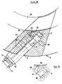
- magnets 1 i which are contiguous or equally interspaced, are fixed along the outer circumference of a cylinder 3 fig. 2 (obviously made from non-magnetic material), and a certain number of magnets 2 i are positioned radially around said cylinder, all of them being provided with an energy restituting system 8, as previously disclosed, it will be possible by suitably timing the action of forces F upon each magnet 2, to move the magnetorotor, i.e. the rotating cylinder 3, with a rotative motion due to the pulling action on said cylinder operated by magnets 1 i .
- the concept is still totally valid if many groups of magnets 1 i and 2 i are stacked (one upon another) as shown in figures 3 and 4.
- Figure 6 shows a possible example of such a way of positioning the magnets, which will be further described below, with the axis of the magnetic field inclined by a desired angle with respect to the faces of the magnets, eventually sidewise stepped by a suitable measure, slightly different for contiguous magnets, in order to correct the little scalar trajectory aberrations owing to the curvature of the parts.
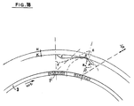
- the magnetic flux baffles 13 have a wall parallel to this axis, the direction of which is substantially parallel to the trajectory of the relative motion of the magnets moved by reciprocating motion with respect to the magnetorotor magnets during the approach stroke.
- the axes of motion of pistons 5 i are substantially parallel to the axes of the magnetic fields of magnets 1 i (fig. 9) or more generally not perpendicular to the outer face of the magnetorotor.
- said flux baffles 13 increase the induction linked to the single magnets in the area more effective for the working of the apparatuses adapt to effect the method subject of the invention, practically eliminating it in the remaining areas, therefore their use is often advisable.
- the same figure 6 shows a further improved embodiment of the apparatus: by means of suitable linking parts 14, many contiguous magnets are connected to one piston. For example, in the case of a 6 cylinder engine, their number is equal to 1/6 of the total number of the magnets installed along a single circumference of rotor 3.
- the form, induction, number and dimensions of the magnets may be varied, and there are several possible ways of aiming the fields and positioning the magnets on the various parts; the most useful solutions will be described, case by case, by the test-work.
- Such an embodiment as a propeller coupled to one or to more than one internal combustion engines is advantageous also as far as the efficiency is concerned. In order to understand this, it will be useful to consider the energy balance of the apparatus, referring, for an easier comprehension, to only one pair of magnets 1, 2, as shown in figure 2.
- the curve of the magnetic attraction force related to the distance is, however, similar to the curve of a "pseudoadiabatic" compression.
- a suitable way to go is to electronically relate, by means of well known methods and devices, the injection and ignition timing to the positions of magnets 2 (or also of the members fixed thereto) with respect to the rotating cylinder, to its rotation speed, to the amount of injected fuel, or to all these factors together, or to others depending on type and way of working of the used electronic control device.
- the electronic control system might also take into account the motion of an operating device (also better explained later on) operated by a driver, device that "activates" a given number of pistons.
- a stopping device for example a stiff ring 23 (fig. 3) stops magnets 2 i from touching magnets 1 i if an accidental compression failure inside a cylinder occurs.
- the axis of pistons 5 i are not necessarily perpendicular to the surface of the magnetorotor 3.
- the magnetorotor rotate a small angle up to the meshing of reference points, for example installed on the rotor and on a non-rotating part, respectively, which the electronic control-box uses to perform its functions. After the first combustion, the apparatus will run automatically.
- the said reference points are not shown in the figures.
- well known means such as a "gear-box" type lever with reduction gear, or a belt and free-wheel device, connected to the rotor or other similar solutions, not shown in the figures.
- the propeller In the stand-by situation (with the vehicle not in motion or even just with the aforementioned pedal at a position 0 in the case of motor vehicles), the propeller is inactive and no combustion occurrs.
- one or more magnets 10 In order to generate the charge-current for the batteries of the vehicle carrying the device according to the invention, it is sufficient to fix one or more magnets 10 to one or more members moved by reciprocating motion (one of these members shown in fig. 4 is a shaft 11 mounted on supporting member 14 also called cursor, of magnets 2 i ) and to mount one or more members 12 on one or many parts of the fixed structure 20, said parts being able to transform the energy produced by the reciprocated mutual approaching and separating motion of said magnets 10 into electric current.
- Said members may be simple induction-coils, on whose end-contacts an alternate voltage will be drawn, a voltage that, when rectified by means of known methods, can generate the charge-current of said battery or batteries.
- a preferred embodiment shows the use of relatively large diameter pistons (pulsors) with a limited compression strokes which are shorter than the distance between two facing magnets when on the border-line of the sensible attraction field.
- the disclosed propeller is applicable in many cases; e.g.: for propulsion purposes on cars, agriculture, transportation and industrial vehicles, coupled to the rotor of helicopters and, more generally, as propeller for a rotating shaft, for example the shaft of a motor-operated current generators.
- the resulting specific fuel consumption is very low, as will be explained later.
- the total weight of the propeller and of all the essential parts is considerably reduced, with all the attained advantages and especially during city-use, owing to the high value of the air/fuel ratio and the relatively low adoptable working temperatures, pollution can be reduced to almost to zero.
- members 1 i and 2 i are both magnetized: one of them, preferably 2 i , may be simply made from a ferromagnetic metal, therewith further reducing the propeller's cost.
- the magnets can be suitably oriented, with or without flux baffles 13 mounted on them (see fig. 6), and can be variously spaced, or quite contiguous.
- a further advantage to point out is the very unlikely probability of failures due to breakages: there are few parts that come in contact and, moreover, an incorrect timing will only reduce the engine's efficiency, even down to zero, but without further risks.
- the fuel is immitted into the combustion chambers 9′ of a selected number of cylinders 9 by means of preferably direct electronic injection, according to the torque or the power needed at each moment.
- control-box an electronic control system of known type, named a control-box and which is programmed in such a way so as to continuously measure various parameters such as rotation speed of magnetorotor 3 (as well as of shaft 7 fixed thereto), its angular acceleration and the will of the driver, will which can be understood from the type of operation: speeding-up or slowing down, which he wanted to effect by moving, for example, the accelerator pedal, the brake pedal or other driving members.
- control-box 42 given its indefinite nature, has been schematically represented only in figure 17.
- the work to be effected for quickly separating said magnets is equal to the total potential energy of the magnetic field, but a part of it will be restituted by the magnetic field in the form of compression work in the next cycle.
- the combustion energy adds itself to the gas expansion's energy, in order to supply the system with the energy which is drawn at each cycle by the magnetorotor 3.
- knowing the mass of all the members integral to the pulsor during its motion, (i.e.) magnets 2 i fixed thereon plus members 14 supporting and connecting them to pulsor 5), and the mass of same pulsor it is easy to determine how much caloric energy is needed in order that the pulsor, after the combustion, and after having separated magnets 1 i and 2 i , keeps a required velocity v p along the direction of its axis.
- the amount of calorific energy (i.e. the fuel amount) is regulated so as to generate the required ratio between said peripheral speed ⁇ r and v p , in such a way as to originate relative motion trajectories, during separating and approaching strokes of magnets 2 i with respect to magnets 1 i , with the most suitable inclination for properly dividing in a required way the magnetic field energy between drawn mechanical work and compression work in the cylinders and/or for obtaining mechanical work according to a rotation sense or to the opposite one.
- members 1 i and 2 i are for conciseness named "magnets", but in reality, when the required power is not high, members 2 i are preferably simple ferromagnetic members, eventually made from thin insulated metal sheets with the axis substantially parallel to the trajectory along which member 2 i run while the linked flux variation reachs its maximum value. That allows smaller variations of the magnetic quantities B and H linked to magnets 1 i during their relative movement with respect to members 2 i , assuring a longer efficiency of magnets 1 i even without a cooling action. As a result the magnetorotor's cost, is considerably reduced.
- the cursor supporting magnet 2 i moving integrally to pulsor 5 even only by effect of mechanical contact, during the outward stroke, meets the restituting system 8 at point B and then, because of losing its kinetic energy at point C, runs back in the opposite direction and (not taking into account energy losses due to friction, which are however very small) with the same kinetic energy, i.e., the masses being constant, with the same (as absolute value) velocity -V p , in the direction represented in figure 16.
- Such ignition in addition to the effect of the expansion of the compressed gas, will cause a quick pressure-increase inside the cylinder when the pulsor finds itself at point A, pulsor which will be pushed back, as already said, at a predetermined velocity v p .
- ⁇ varies depending on the supplied power, i.e. on the return-stroke length of the pulsors, and again according to such stroke the amount of fuel to be burnt in a cycle is different, said amount being proportional to the total work to make in order to separate magnets 2 i from magnets 1 i ;
- the amount of air in the cylinder which as matter of fact results much higher than the minimum stoichimetric value, is, on the contrary, constant.
- the temperature increase in a cycle due to the combustion also varies according to the drawn power, and similar is the behaviour of the temperature-increase due to the compression of the gases inside the cylinder.
- the force, which acts on the pulsors in order to separate the magnets with an acceleration sufficient to let them follow the trajectory shown in figure 16 is evaluated.
- the move-away line must be at least perpendicular to the magnetorotor already at point x, and that is obtainable by means of a pulsor-velocity v p approximately equal to 1,5 times the peripheral velocity of the magnetorotor after a very short time, which can for instance be assumed as equal to the time of a tangential relative movement of 1 6 ⁇ 1 10 of their width 1.
- the energy supplied by the fuel is equal to the total magnetic work in the cycle (ignoring the efficiency ratios).
- the final pulsor velocity in B is easily calculable, that is its velocity at the beginning of the compression of the resilient members of the mechanical energy restituting system.
- the times of pulsor strokes AB and EF are easily calculated.
- the engine subject of the invention shows a specific fuel-consumption much lower than the traditional engines, with much lower pollution.
- the details of ignition and combustion of the fuel shall be determined, case by case, by technicians skilled in the engines field, taking into account the new situations of compression and temperatures, (which vary depending on the power used), in order to achieve the best work-cycle for each use-condition.
- a successful solution is suggested by fig. 12: the fuel is ejected by injectors 43 directly toward electrodes 33 (as in multifuel engines), which the fuel reaches after mixing with a prefixed mass of air.
- Such air (conceptually corresponding to the primary air of the after-burning technology) will be formed from the air contained inside the pre-chamber 44 in addition to the air "sucked" by the fuel-jet through one or more than one air-ducts (46) because of Venturi effect.
- prechamber 44 is substantially “self-regulating”: inside said prechamber at a certain compression ratio, a given mass of air is lodged, which combines itself with the amount of fuel needed for separating the magnets which are at the distance corresponding to said compression stage: by increasing the compression, at the same time the amount of fuel needed for separating the magnets and the air mass is increased, since they were closer than in the previous situation.
- the mass of air increases according to the compression curve, the amount of fuel increases according to the attraction-force curve depending on the distance between the magnets.
- the latter curve has a trend fairly similar to the adiabatic curve trend, and the relatively small differences of the various distance between the magnets can be corrected by regulating the strength of the compound generated in prechamber 44, modifying (very slightly) the amount of fuel, or the number of air-ducts (46), or the injection-pressure, or the prechamber volume, or all these factors together.
- Many pairs of electrodes can be installed along the longitudinal axis of the prechamber, so as to make it possible to start the ignition when the fuel is mixed with the required amount of air. (This case is not represented in the drawings).
- a substantially transverse pressurized air-jet as shown in figure 10.
- a jet can be formed in various ways, with or without a pressurized air resevoir 32 acting as plenum chamber, by means of a compressor, with rotating members which is connected to the drive-shaft, or operated by electrical energy supplied for example by the batteries of the vehicle in which the engine is installed.
- valve 25 is not essential for the cycle inside cylinder 9. Nevertheless said valve can sometimes be useful for avoiding an inadequate scavenge-air consumption by closing it in case, e.g., the total outward stroke of the pulsor is considerably higher than the expansion-stroke. Such a case will be described later.
- the shape of the section, its area and the useful stroke of such pistons 26 may be varied accordingly to the required pressurized-air flow-rate.
- the aforementioned compression can be effected during the return-stroke of pulsor 2, as represented in figure 10, or during their outward stroke (case not represented in the drawings).
- Said system is especially suitable for the embodiment preferred by the inventor for not too high powers, wherein there are as many cylinders as magnets fixed along an outer circumference of magnetorotor 3.
- the pistons can be replaced with simple, preferrably hollow shafts carrying pressure-seal rings 31, the cost of the parts is so low, that the use of the said volumetric compressing pistons is advantageous, provided that their use would not cause unacceptable variations of the trajectory of magnets 2 i .
- an alternative independent air-compressing system may be used, both electric or eventually mechanically connected to drive-shaft 7 or to a secondary shaft derived therefrom.
- the aspect of the engine is shown in fig. 13. Given the high reaction-torque transmitted to the supporting frame, (the maximum rotation speed for usual appliances, is not higher than 6-10 revolutions per second), it is useful to split the required power in two by means of two counter-rotating engines which are mechanically in parallel or, by means of a known rotation reversing device, 35 fig. 15, in series. In order to reduce the strains on members 14 (cursors) which support magnets 2 i , and thus their mass and the related inertial force, the inventor foresees to insert each engine between two half magnetorotors (fig. 14). Such a solution also helps bushings 21 fig.
- cooling fins mounted on said cylinder-casings will further improve the heat exchange.
- suitably oriented air streams may be used, and they may be generated by the vehicle motion or by cooling fans.
- the air-cooling system were inadequate, it would be easy to cool the engine down by means of an heat transferring fluid circulating inside annular or otherwise shaped jackets to be mounted around the cylinder-casings.
- magnetorotors carry magnets 1 i interspaced by at least a 50 ⁇ 70 % of their width, in order to avoid interferences among the magnetic fields. All around the engine 6 there is a plurality of free spaces between two adjacent cursors 14 supporting a certain number of overlaid magnets. In case that magnets 1 i , by the effect of flux-baffles fixed thereto, may be contiguous, it will be sufficient to lose a certain percentage of power, eliminating opposite pairs of cursors 14. Given the relatively low temperatures, in the engine of the invention the lubricating system by means of an heat transfering fluid is normally not needed.
- Each pulsor in fact, by the effect of the transversal scavenging air-jet, even if at a pressure of 3 Kg/cm2, exerts a pressure against the cylinder wall corresponding approximately to 0,8 ⁇ 1,5 Kg/cm2, with a maximum piston velocity of about 12 m/sec.
- Pulsor 5, and consequently cylinders 1 never support any pressure besides that mentioned above, and the limited pressure given by the seal rings, not supporting other different kinds of forces having components not parallel to the cylinders axes.
- duct 29 of the scavenging air-jet it will be useful to shape it as orientatively shown in fig. 11, in order to perform an efficient scavenge in the direction of the arrows also with a not high pressure and to be able to eventually exploit part of the same pressure (the part which, because of the tortuosness of the way does not transform itself into kinetic energy) as first stage of the compression inside the cylinder, or for creating a turbulence inside the cylinder.
- Magnets 2 i which are inactive at this stage, oscillate staying at an intermediate distance, between the field-limit and magnets 1, which does not generate undesirable Foucault effects, at the intersection point between the pressures curve and the attraction forces curve of the magnetic field.
- the engine according to the invention either when the vehicle is not going, or even just when the accelerator-pedal is totally released, is inactive and doesn't burn fuel (or emit exhaust gases). It is of interest to note that, by quickly releasing the accelerator pedal, and deactivating (intending to slow-down the vehicle), the pulsors, they, devoid of the kinetic energy supplied by fuel, will follow, with decreasing stroke-length, trajectories no longer adapt to generate a working torque, but on the contrary, generate a braking torque, as said trajectories will cross the magnets attraction field in such a way as to slow-down the magnetorotor motion as well as the thereto connected drive-shaft 7.
- the vehicle is slowed down (braking-motor effect), in co-operation with the existing braking-system.
- a gear box is in certain cases not strictly needed: also the reverse motion, for example, will be in some cases achievable by means of suitable trajectories (AKZ fig. 16).
- the engine works, as previously stated, with a variable compression, increasing together with the increasing power, and with the need, as also said , to increase the fuel quantity.
- the resulting air volume inside the cylinders considerably exceeds the stoichiometrically required volume: consequently the substantial absence of CO, HC and of many nitrogen compounds whithin the gas is achieved, and a good combustion efficiency is also achieved at low speeds, with low compression ratios.
- the drive shaft rotation speed (6 : 10 r/sec) is in fact, very close to the commonly adopted rotation speed of the propeller-shaft.
- the heat emitted by motor 6 by radiation can easily be kept from reaching the magnets 1 of the magnetorotor 3 by applying an insulating layer covered by a thin sheet of reflecting material to the inside of magnetorotor 3.
- the low level of heat eventually produced by the magnets because of parasitic currents or because of other energy losses is automatically removed by air by the effect of the pulsating motion of cursors 14 combined with the rotative motion of magnetorotor 3.
- the device shows, in one of the preferred embodiments, a stiff member 40 fixed to the radially outer ends of elements 8 elastic to the compression stress spring (in the case shown) which have to take up the maximum kinetic energy of a pulsor 5 or of a group of mechanically connected pulsors by means of a prefixed maximum set.
- a flat plate 37 parallel to the slidable facing member 40, is interposed between same member 40 and a fixed structure 20, said plate carrying at least one wedge-shaped projecting part 37′, the thickness of which decreases along its longitudinal axis, at positions corresponding to each elastic element 8 or group of elastic elements.
- the wedge-shaped projecting parts 37′ fit between member 40 and structure 20, modifying the distance between them from zero up to the maximum thickness of the wedge-shaped projecting part.
- a projecting part 37′ when not totally inserted between member 40 and structure 20, projects sideways through holes 40′ formed on same member.
- Many methods can be used to allow said slidable plate 37 to slide, for example, fixing one end 37 ⁇ thereof to the keeper of an electromagnet 38, whose induction current is controlled by the engine's control box, which determines its stroke according to the angular speed or acceleration, to the instructions given by the driver, or to the length of the compression stroke run in the last cycle, or to many of these factors combined with each other.
- a further method for moving slidable plate 37 may be by connecting it to a pneumatic, oil-operated or similarly operated piston, "driven” by the control-box, or to insert a sealed expandable chamber between member 40 and fixed structure 20, regulating, again by means of the control-box, its thickness, or to use other methods not shown in the drawings.
Landscapes
- Engineering & Computer Science (AREA)
- Chemical & Material Sciences (AREA)
- Nanotechnology (AREA)
- Crystallography & Structural Chemistry (AREA)
- General Engineering & Computer Science (AREA)
- Health & Medical Sciences (AREA)
- Life Sciences & Earth Sciences (AREA)
- General Health & Medical Sciences (AREA)
- Molecular Biology (AREA)
- Combustion & Propulsion (AREA)
- Power Engineering (AREA)
- Mechanical Engineering (AREA)
- Reciprocating, Oscillating Or Vibrating Motors (AREA)
- Transmission Devices (AREA)
- Recording Or Reproducing By Magnetic Means (AREA)
- Nozzles (AREA)
- Forging (AREA)
- Testing Of Balance (AREA)
- Combustion Methods Of Internal-Combustion Engines (AREA)
- Vehicle Body Suspensions (AREA)
- Electrical Control Of Air Or Fuel Supplied To Internal-Combustion Engine (AREA)
- Output Control And Ontrol Of Special Type Engine (AREA)
Applications Claiming Priority (3)
| Application Number | Priority Date | Filing Date | Title |
|---|---|---|---|
| CH1978/91 | 1991-07-03 | ||
| CH1978/91A CH683217A5 (it) | 1991-07-03 | 1991-07-03 | Procedimento che utilizza l'azione di campi magnetici permanenti per muovere un sistema di corpi lungo una traiettoria muovendone un secondo di moto alternato. |
| PCT/EP1992/001462 WO1993001647A1 (en) | 1991-07-03 | 1992-06-29 | Magnetic device for converting reciprocating into rotating motion |
Publications (2)
| Publication Number | Publication Date |
|---|---|
| EP0593545A1 EP0593545A1 (en) | 1994-04-27 |
| EP0593545B1 true EP0593545B1 (en) | 1995-05-10 |
Family
ID=4223057
Family Applications (1)
| Application Number | Title | Priority Date | Filing Date |
|---|---|---|---|
| EP92913726A Expired - Lifetime EP0593545B1 (en) | 1991-07-03 | 1992-06-29 | Magnetic device for converting reciprocating into rotating motion |
Country Status (12)
| Country | Link |
|---|---|
| US (1) | US5415140A (it) |
| EP (1) | EP0593545B1 (it) |
| JP (1) | JP3179488B2 (it) |
| AT (1) | ATE122508T1 (it) |
| AU (1) | AU661009B2 (it) |
| BR (1) | BR9206217A (it) |
| CA (1) | CA2111203C (it) |
| CH (1) | CH683217A5 (it) |
| DE (1) | DE69202460T2 (it) |
| DK (1) | DK0593545T3 (it) |
| ES (1) | ES2071506T3 (it) |
| WO (1) | WO1993001647A1 (it) |
Families Citing this family (15)
| Publication number | Priority date | Publication date | Assignee | Title |
|---|---|---|---|---|
| EP0833074B1 (en) * | 1996-04-08 | 2004-06-23 | Delta Tooling Co., Ltd. | Magnetic spring having damping characteristics and vibration mechanism having same |
| JP3725272B2 (ja) * | 1996-12-27 | 2005-12-07 | 株式会社デルタツーリング | 振動発生機構 |
| CA2196340C (en) * | 1997-01-30 | 2001-07-03 | Nung-Soo P. Kim | Three pole forced permanent magnet rotor with dc twister |
| HRP970251B1 (en) * | 1997-05-12 | 2007-05-31 | Grbavac Kazimir | Double-piston engine with hydraulic connection between the pistons and the main driving shaft |
| JPH1130274A (ja) * | 1997-05-15 | 1999-02-02 | Delta Tsuuring:Kk | 磁気バネを有する振動機構 |
| KR100281474B1 (ko) | 1997-05-16 | 2001-02-01 | 후지타 히토시 | 자기스프링을구비한에너지출력기구 |
| WO2002091498A2 (en) * | 2001-05-09 | 2002-11-14 | Harmonic Drive, Inc. | Linear magnetic harmonic motion converter |
| US20070210659A1 (en) * | 2006-03-07 | 2007-09-13 | Long Johnny D | Radial magnetic cam |
| US8113165B2 (en) * | 2009-02-16 | 2012-02-14 | Russell Energy Corporation | Stationary block rotary engine/generator |
| US8664816B1 (en) | 2010-09-01 | 2014-03-04 | Magnamotor, Llc | Magnetic reaction apparatus, assembly and associated methods for optimization of a cyclic drive input |
| US8508089B2 (en) | 2010-09-01 | 2013-08-13 | Magnamotor, Llc | Magnetic drive motor assembly and associated methods |
| US20130147297A1 (en) * | 2011-12-08 | 2013-06-13 | Harold Elmore | Magnetic Motor Propulsion System |
| US9077093B1 (en) * | 2014-04-23 | 2015-07-07 | Apple Inc. | Magnetic rotation actuator |
| US10790066B2 (en) * | 2017-12-04 | 2020-09-29 | Westinghouse Electric Company Llc | Rotational apparatus usable with control drum apparatus in nuclear environment |
| CN111535952B (zh) * | 2020-05-10 | 2022-08-12 | 陈超胜 | 一种废气再利用的磁力增压型发动机进气过滤装置 |
Family Cites Families (12)
| Publication number | Priority date | Publication date | Assignee | Title |
|---|---|---|---|---|
| GB747682A (en) * | 1953-07-22 | 1956-04-11 | Muirhead & Co Ltd | Improvements in or relating to magnetic clutches or brakes |
| US3523204A (en) * | 1968-01-19 | 1970-08-04 | Sydney Rand | Magnetic transmission system |
| US3992132A (en) * | 1975-02-04 | 1976-11-16 | Putt J William | Energy conversion system |
| FR2307132A1 (fr) * | 1975-04-10 | 1976-11-05 | Guillon Marcel | Dispositifs d'un nouveau moteur rotatif a combustion interne, a pistons libres et cylindres a plat disposes en etoile; pistons accouples en partie inferieure " jupes " avec galets rotatifs en contact de rotation crantes avec rotor interieur triangulaire par force mecanique, pneumatique et magnetique |
| US4169983A (en) * | 1976-09-22 | 1979-10-02 | Felder Donald W | Multi-rotor, direct current electric motor |
| US4207773A (en) * | 1976-11-04 | 1980-06-17 | Stahovic Robert F | Magnetic piston machine |
| US4127036A (en) * | 1977-05-07 | 1978-11-28 | Pinto Adolf P | Engine having alternately rotating orbital pistons and cylinders |
| US4571528A (en) * | 1983-06-21 | 1986-02-18 | Magna Motive Industries, Inc. | Electromagnetic rotary motor |
| EP0152252A3 (en) * | 1984-02-09 | 1986-07-30 | Uni Com Corporation | Permanent magnet prime mover |
| US4794901A (en) * | 1987-06-16 | 1989-01-03 | Industrial Technology Research Institute | Low pressure air assisted fuel injection apparatus for engine |
| GB2219671B (en) * | 1988-04-26 | 1993-01-13 | Joseph Frank Kos | Computer controlled optimized hybrid engine |
| US4949000A (en) * | 1988-07-18 | 1990-08-14 | Mueller And Smith, Lpa | D.C. motor |
-
1991
- 1991-07-03 CH CH1978/91A patent/CH683217A5/it not_active IP Right Cessation
-
1992
- 1992-06-29 AT AT92913726T patent/ATE122508T1/de not_active IP Right Cessation
- 1992-06-29 JP JP50192993A patent/JP3179488B2/ja not_active Expired - Fee Related
- 1992-06-29 AU AU21941/92A patent/AU661009B2/en not_active Ceased
- 1992-06-29 US US07/916,994 patent/US5415140A/en not_active Expired - Fee Related
- 1992-06-29 EP EP92913726A patent/EP0593545B1/en not_active Expired - Lifetime
- 1992-06-29 DE DE69202460T patent/DE69202460T2/de not_active Expired - Fee Related
- 1992-06-29 BR BR9206217A patent/BR9206217A/pt not_active IP Right Cessation
- 1992-06-29 WO PCT/EP1992/001462 patent/WO1993001647A1/en active IP Right Grant
- 1992-06-29 CA CA002111203A patent/CA2111203C/en not_active Expired - Fee Related
- 1992-06-29 ES ES92913726T patent/ES2071506T3/es not_active Expired - Lifetime
- 1992-06-29 DK DK92913726.3T patent/DK0593545T3/da not_active Application Discontinuation
Also Published As
| Publication number | Publication date |
|---|---|
| US5415140A (en) | 1995-05-16 |
| DE69202460D1 (de) | 1995-06-14 |
| ES2071506T3 (es) | 1995-06-16 |
| JPH07502158A (ja) | 1995-03-02 |
| BR9206217A (pt) | 1994-12-20 |
| CH683217A5 (it) | 1994-01-31 |
| AU661009B2 (en) | 1995-07-13 |
| CA2111203A1 (en) | 1993-01-21 |
| DK0593545T3 (da) | 1995-10-09 |
| DE69202460T2 (de) | 1995-09-14 |
| WO1993001647A1 (en) | 1993-01-21 |
| CA2111203C (en) | 2001-10-23 |
| ATE122508T1 (de) | 1995-05-15 |
| EP0593545A1 (en) | 1994-04-27 |
| AU2194192A (en) | 1993-02-11 |
| JP3179488B2 (ja) | 2001-06-25 |
Similar Documents
| Publication | Publication Date | Title |
|---|---|---|
| EP0593545B1 (en) | Magnetic device for converting reciprocating into rotating motion | |
| Mikalsen et al. | A review of free-piston engine history and applications | |
| RU2255232C2 (ru) | Устройство, включающее в себя двигатель внутреннего сгорания, использование такого устройства, а также транспортное средство | |
| EP0766781B1 (en) | Linear electrical energy generator | |
| CA2001712C (en) | Computer controlled optimized hybrid engine | |
| CN101506472B (zh) | 混合循环旋转发动机 | |
| US5881559A (en) | Hybrid electric vehicle | |
| US4326380A (en) | Hydraulic engine | |
| JP2009516801A (ja) | フリーピストン式4ストロークエンジン | |
| US20150114352A1 (en) | Torque multiplier engines | |
| US8161921B2 (en) | Method to convert free-piston linear motion to rotary motion | |
| CN103299046A (zh) | 高效率的线性内燃机 | |
| JPH0674749B2 (ja) | 複合タービン機関 | |
| US20060278181A1 (en) | Internal combustion engine with freewheeling mechanism | |
| EP0152252A2 (en) | Permanent magnet prime mover | |
| JPH0794801B2 (ja) | 回転・往復ピストン・マシン | |
| US8511060B1 (en) | External combustion engine with a general wheel rotation power motor | |
| US20060242940A1 (en) | Rotary engine using traditional pistons of flexible motion | |
| JP6316191B2 (ja) | 軌道式の非往復動内燃機関 | |
| JPH0263093B2 (it) | ||
| KR20190040435A (ko) | 초효율에너지와 프리에너지를 동력으로 하는 비행기 | |
| RU2083850C1 (ru) | Роторный двигатель внутреннего сгорания | |
| JPH116451A (ja) | 磁気摩擦動力伝達装置を含む駆動装置及び駆動方法 | |
| RU2176025C1 (ru) | Тепловая электрогенерирующая машина | |
| JPH1073020A (ja) | エネルギ保存サイクル機関の利用方法及び装置 |
Legal Events
| Date | Code | Title | Description |
|---|---|---|---|
| PUAI | Public reference made under article 153(3) epc to a published international application that has entered the european phase |
Free format text: ORIGINAL CODE: 0009012 |
|
| 17P | Request for examination filed |
Effective date: 19940119 |
|
| AK | Designated contracting states |
Kind code of ref document: A1 Designated state(s): AT BE DE DK ES FR GB GR IT LU NL SE |
|
| 17Q | First examination report despatched |
Effective date: 19940706 |
|
| ITF | It: translation for a ep patent filed |
Owner name: FIAMMENGHI FIAMMENGHI RACHELI |
|
| GRAA | (expected) grant |
Free format text: ORIGINAL CODE: 0009210 |
|
| AK | Designated contracting states |
Kind code of ref document: B1 Designated state(s): AT BE DE DK ES FR GB GR IT LU NL SE |
|
| REF | Corresponds to: |
Ref document number: 122508 Country of ref document: AT Date of ref document: 19950515 Kind code of ref document: T |
|
| ET | Fr: translation filed | ||
| REF | Corresponds to: |
Ref document number: 69202460 Country of ref document: DE Date of ref document: 19950614 |
|
| REG | Reference to a national code |
Ref country code: ES Ref legal event code: FG2A Ref document number: 2071506 Country of ref document: ES Kind code of ref document: T3 |
|
| REG | Reference to a national code |
Ref country code: GR Ref legal event code: FG4A Free format text: 3016777 |
|
| REG | Reference to a national code |
Ref country code: DK Ref legal event code: T3 |
|
| PLBE | No opposition filed within time limit |
Free format text: ORIGINAL CODE: 0009261 |
|
| STAA | Information on the status of an ep patent application or granted ep patent |
Free format text: STATUS: NO OPPOSITION FILED WITHIN TIME LIMIT |
|
| 26N | No opposition filed | ||
| REG | Reference to a national code |
Ref country code: GB Ref legal event code: IF02 |
|
| PGFP | Annual fee paid to national office [announced via postgrant information from national office to epo] |
Ref country code: BE Payment date: 20030613 Year of fee payment: 12 |
|
| PGFP | Annual fee paid to national office [announced via postgrant information from national office to epo] |
Ref country code: SE Payment date: 20030617 Year of fee payment: 12 Ref country code: GB Payment date: 20030617 Year of fee payment: 12 |
|
| PGFP | Annual fee paid to national office [announced via postgrant information from national office to epo] |
Ref country code: ES Payment date: 20030619 Year of fee payment: 12 |
|
| PGFP | Annual fee paid to national office [announced via postgrant information from national office to epo] |
Ref country code: GR Payment date: 20030620 Year of fee payment: 12 |
|
| PGFP | Annual fee paid to national office [announced via postgrant information from national office to epo] |
Ref country code: DE Payment date: 20030624 Year of fee payment: 12 |
|
| PGFP | Annual fee paid to national office [announced via postgrant information from national office to epo] |
Ref country code: DK Payment date: 20030626 Year of fee payment: 12 |
|
| PGFP | Annual fee paid to national office [announced via postgrant information from national office to epo] |
Ref country code: NL Payment date: 20030627 Year of fee payment: 12 Ref country code: FR Payment date: 20030627 Year of fee payment: 12 |
|
| PGFP | Annual fee paid to national office [announced via postgrant information from national office to epo] |
Ref country code: AT Payment date: 20030630 Year of fee payment: 12 |
|
| PGFP | Annual fee paid to national office [announced via postgrant information from national office to epo] |
Ref country code: LU Payment date: 20030703 Year of fee payment: 12 |
|
| PG25 | Lapsed in a contracting state [announced via postgrant information from national office to epo] |
Ref country code: LU Free format text: LAPSE BECAUSE OF NON-PAYMENT OF DUE FEES Effective date: 20040629 Ref country code: GB Free format text: LAPSE BECAUSE OF NON-PAYMENT OF DUE FEES Effective date: 20040629 Ref country code: AT Free format text: LAPSE BECAUSE OF NON-PAYMENT OF DUE FEES Effective date: 20040629 |
|
| PG25 | Lapsed in a contracting state [announced via postgrant information from national office to epo] |
Ref country code: SE Free format text: LAPSE BECAUSE OF NON-PAYMENT OF DUE FEES Effective date: 20040630 Ref country code: ES Free format text: LAPSE BECAUSE OF NON-PAYMENT OF DUE FEES Effective date: 20040630 Ref country code: DK Free format text: LAPSE BECAUSE OF NON-PAYMENT OF DUE FEES Effective date: 20040630 Ref country code: BE Free format text: LAPSE BECAUSE OF NON-PAYMENT OF DUE FEES Effective date: 20040630 |
|
| BERE | Be: lapsed |
Owner name: *RIGAZZI PIER ANDREA Effective date: 20040630 |
|
| PG25 | Lapsed in a contracting state [announced via postgrant information from national office to epo] |
Ref country code: NL Free format text: LAPSE BECAUSE OF NON-PAYMENT OF DUE FEES Effective date: 20050101 Ref country code: DE Free format text: LAPSE BECAUSE OF NON-PAYMENT OF DUE FEES Effective date: 20050101 |
|
| PG25 | Lapsed in a contracting state [announced via postgrant information from national office to epo] |
Ref country code: GR Free format text: LAPSE BECAUSE OF NON-PAYMENT OF DUE FEES Effective date: 20050105 |
|
| REG | Reference to a national code |
Ref country code: DK Ref legal event code: EBP |
|
| EUG | Se: european patent has lapsed | ||
| EUG | Se: european patent has lapsed | ||
| GBPC | Gb: european patent ceased through non-payment of renewal fee |
Effective date: 20040629 |
|
| PG25 | Lapsed in a contracting state [announced via postgrant information from national office to epo] |
Ref country code: FR Free format text: LAPSE BECAUSE OF NON-PAYMENT OF DUE FEES Effective date: 20050228 |
|
| NLV4 | Nl: lapsed or anulled due to non-payment of the annual fee |
Effective date: 20050101 |
|
| REG | Reference to a national code |
Ref country code: FR Ref legal event code: ST |
|
| PG25 | Lapsed in a contracting state [announced via postgrant information from national office to epo] |
Ref country code: IT Free format text: LAPSE BECAUSE OF NON-PAYMENT OF DUE FEES Effective date: 20050629 |
|
| REG | Reference to a national code |
Ref country code: ES Ref legal event code: FD2A Effective date: 20040630 |