EP0592929A1 - Maschine zur Herstellung von Stator-Blechpaketen - Google Patents
Maschine zur Herstellung von Stator-Blechpaketen Download PDFInfo
- Publication number
- EP0592929A1 EP0592929A1 EP93116109A EP93116109A EP0592929A1 EP 0592929 A1 EP0592929 A1 EP 0592929A1 EP 93116109 A EP93116109 A EP 93116109A EP 93116109 A EP93116109 A EP 93116109A EP 0592929 A1 EP0592929 A1 EP 0592929A1
- Authority
- EP
- European Patent Office
- Prior art keywords
- punchings
- stack
- height
- vertical
- punching
- Prior art date
- Legal status (The legal status is an assumption and is not a legal conclusion. Google has not performed a legal analysis and makes no representation as to the accuracy of the status listed.)
- Granted
Links
Images


Classifications
-
- H—ELECTRICITY
- H02—GENERATION; CONVERSION OR DISTRIBUTION OF ELECTRIC POWER
- H02K—DYNAMO-ELECTRIC MACHINES
- H02K15/00—Processes or apparatus specially adapted for manufacturing, assembling, maintaining or repairing of dynamo-electric machines
- H02K15/02—Processes or apparatus specially adapted for manufacturing, assembling, maintaining or repairing of dynamo-electric machines of stator or rotor bodies
Definitions
- This invention relates to a new process for building ferromagnetic lamination stacks used in the manufacture of stators, in particular stators of electric motors.
- Such a manufacturing technology is essentially based on following manufacturing cycle, which is shortly described here in order to enable a comparison to be more easily and clearly made between said manufacturing cycle and the new cycle according to the present invention, which will be described later on.
- the first step encountered in the traditional manufacturing cycle involves each single lamination being punched and cut to shape for subsequent stacking with other similar punchings to form the lamination stack.
- the second phase involves said punchings being annealed, ie. heat-treated, whereas the third step involves said punchings, which are now available in great amounts in a stacked form, being aggregated to a certain amount so as to achieve the desired size and, therefore, the desired characteristics of the stator lamination stack.
- such an aggregation step itself involves a sequence of sub-steps, wherein the first one of these sub-steps is the separation, from the previously formed big stack of punchings, of the laminations that are intended to exactly build up a stator lamination stack.
- stator lamination stacks formed by a number of single sheet-metal punchings being joined together, whereas such a process is capable of both preventing said laminations sticking together from causing process stops, and therefore downtime problems, and enabling the entire cycle for the preparation of said lamination stacks to be fully automated.
- the process according to the present invention is essentially based on the fact that the punchings used to form the stator lamination stack are not being picked from the bottom of the related stack into which the punchings have been previously aggregated, but they are on the contrary picked from the top of said stack; the process is further based on a single driving and control system which is programmable and acting on the various moving members of the equipment involved. This enables a number of further advantages to be obtained, as it will become apparent from the description below.
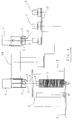
- the equipment shown in the Figures comprises a platform 1 carrying a number of vertical elements 2; corresponding stacks 3 of punchings, which have been previously annealed and are ready to be associated into smaller groups so as to form a plurality of stator lamination stacks, are inserted on said vertical elements with traditional means (Fig. 1).
- Each one of said vertical elements 2 is provided with means 12, which are well-known in the art and controlled by the same driving and control system. These means, which will not be described here any further for the sake of simplicity, since their construction and operation are easily understood by anyone skilled in the art, are used to lift and lower the respective stacks of punchings.
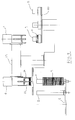
- a picking head 4 rests on the structure of the equipment and lies above a determined stack of punchings.
- This head is provided with a plurality of vertical, moving lifting and picking arms 5 which, when correspondingly controlled by driving and control systems as they are widely known in the art, are capable of being moved downwards and catch a particular punching by means of seizing claws 6 that are arranged at the lower end of said arms 5.
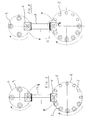
- Said head 4 is further provided with a plurality of separation wedges 8 which are arranged circularly and radially at a same height around the stack of punchings 3. Said wedges are oriented towards the centre of the stack and are capable of moving radially inwards so as to intercept the punchings in the stack.
- the head 4 is provided with a displacement sensing element 7 connected with a common driving and control system, said displacement sensing element 7 consisting essentially of a vertical moving arm which projects from the downward looking side of the head 4 and is adapted to move elastically upwards under the action of a solid moving vertically upwards, ie. the stack of punchings in this particular case, so that when this solid is lifted to the point it touches the lower end of said moving arm, the upward displacement that is induced on said moving arm defines the height of the top of the stack which, when compared with the height of the bottom, or base, of the same stack, ie. an information that is already known to the control system, immediately gives the total height of the punchings forming the stack.
- a solid moving vertically upwards ie. the stack of punchings in this particular case
- the process according to the present invention is as follows: When the process is started, the turning platform 1, with its vertical elements 2 supporting respective stacks of punchings, turns until it reaches a position in which a stack of punchings 3 is brought to lie exactly under the picking head 4. When said position of the turning platform 1 is reached, the means 12 provided for lifting and lowering the stack of punchings are actuated to lift said stack up to the point in which the surface of the punching 3', which lies on top of the stack 3, comes into contact with and start to push upwards the lower end of said displacement sensing element 7 (Fig. 2).
- the driving and control system of the equipment acquires the information concerning the height of the stack of punchings 3, since such a system receives at the same time also the data relating to the lifting of the stack 3, as actuated by the means 12.
- the height of the stack of punchings being processed in a given moment be different from the sum of the heights of the lamination stacks 11 that can be derived from it.
- this is detected immediately at the beginning of the process cycle, ie. when the vertical element 2 carrying the stack of punchings involved is lifted for the first time up to the point in which the displacement sensing element 7 feels the pushing action of the top punching 3', so that the driving and control system of the equipment is enabled to immediately find out by calculation the height of stack and divide it by the height of the required stator lamination stack. Should such a division fail to result in a whole number (of stator lamination stacks) and there is actually an excess portion of punchings, the system reacts as follows:
- the driving and control system of the equipment After having in this way acquired the height of the stack of punchings, and knowing already the required height of the stator lamination stack 11 since it is a pre-programmed information, the driving and control system of the equipment immediately calculates both the number of stator lamination stacks that can be derived therefrom and, at the same time, the residual height of punchings that cannot be used from that stack since their total height falls short of the actual height required for a stator lamination stack. It then stores in its memory the information concerning said height of excess punchings in the stack.
- the system provides for the stack 3 of punchings being processed to be lifted by means of the lifting and lowering means 12 by such a height that the separation wedges 8 are able to get inserted in the stack at the height of a punching which has been selected to lie at a vertical distance from the punching 3' at the top of the stack that is equal to the programmed height of the stator lamination stack (Fig. 2).
- Said separation wedges do not actually get into the stack of punchings, but just grip the lower punchings above the selected punching, so that when the lifting and lowering means 12 causes the stack of punchings to be lowered, the whole stack sinks except for the portion of punchings above said selected punching (Fig. 3).
- the lifting and picking arms 5 are lowered and clamped in such a way that the lifting claws 6 get clamped around and under the punches being held by the separation wedges. Thereupon, said separation wedges are withdrawn, thereby allowing the suspended punchings to lie down on said lifting claws (Fig. 4).
- a simplified alternative to the above described process consists in detecting the height of the stack of punchings as soon as it is brought into the process, whereas the number of stator lamination stacks that can be derived therefrom is calculated as in the above described method. Then the single stator lamination stacks are picked up to the last whole stack. At this moment the equipment changes to a new stack of punchings, while leaving the residual punchings on the formerly processed, just moved-off stack. This is then in a condition as to be replenished with a suitable amount of new punchings to restore the height of the stack, while considering that this height is actually not a critical process parameter.
- the process can be considered as to end here, since it is at this point possible to remove the stack of punchings that have been separated in the afore described way and that are forming exactly a stator lamination stack.
- a first variant provides the use of handling means 13 that act on the just formed lamination stack 11 and transfer it on to a unloading vertical element 9 which retains said lamination stack 11 with its punchings still orderly arranged and resting horizontally upon each other, said unloading vertical element 9 being located, exactly as the formerly cited vertical elements 2, on a corresponding turning platform 10, from which each stator lamination stack is then withdrawn to complete the remaining manufacturing phases in a more or less traditional manner (Figs. 1, 5).
- said handling means can be provided through a proper rotary movement imparted to the head 4 which, after unloding the stator lamination stack on to the corresponding vertical element 9, returns to its initial position in order to start a new cycle.
- the driving and control system uses the process described below to pick up these punchings to unload them on to a new vertical element 9. Then it causes the turning platform 1 to revolve to such an extent that a new stack of punchings is brought under the picking head 4, from which the cycle is started anew with the vertical element now placed under said head being raised so that the height of the stack of punchings being now processed can be determined.
- the manufacturing cycle is then continued in the afore described way, with the driving and control system that now calculates anew, and stores in its memory, the "new" height of the punchings left in the stack of punchings being process, so as to enable the equipment to handle said punchings in the afore illustrated way and go through the described manufacturing process.
- a further improvement to the process according to the invention is based on the fact that, due to the punchings not being perfectly planar after the annealing phase of the manufacturing process, corresponding mechanical and functional divergences occur in the same generants on the same stack, which therefore are converted into a corresponding lack of homogeneity in the behaviour of the resulting stators.
- Transfer means are therefore provided from the vertical elements 2 to the unloading vertical elements 9, said transfer means being essentially adapted to divide the lamination stack formation process into two distinct, basically similar processes, in each one of them a half stator lamination stack is actually selected and transferred on to a common vertical element 9, said processes differing from each other only in that one of them also comprises a phase provided to turn the respective half stack by 180° around a horizontal axis.
- a further improvement is thereby achieved in the case that, due to possible errors in the planarity of the punchings as they may actually occur quite frequently, the stack clamping wedges do not tighten their grip exactly between the selected punching in the stack and the punching immediately thereunder, but get positioned against a punching that may lie more or less immediately above or under the punching that would have been selected in case of correct planarity and, therefore, cause a half-stack to be withdrawn with one or more punchings more or less than actually required, even if the total height of the stack appears to be correct.
- a special control station is provided to act on the lamination stack as soon as the latter is formed and being transferred on to the respective vertical element 9 located on the revolving unloading platform 10.
- Said control station comprises a pushing member 21 which acts with a downward movement and whose vertical displacement is detected by a device that is not further described here since it is well-known in the art (Fig. 8).
- Said pushing member is applied successively with a certain downward force on each lamination stack 25 being unloaded on to said vertical elements 9. If the displacement of this pushing member with respect to a pre-determined height reference turns out to be equal to a pre-determined value corresponding to the correct number of punchings in the lamination stack, then the pushing member is raised and the just checked stator lamination stack is sent on to the further processing steps of the manufacturing cycle.
- a particularly advantageous alternative embodiment is obtained by replacing the plurality of wedges 8 with a plurality of wedges that are differently intercalated with a plurality of plane elements that rest on and are pressed against the vertical edges of the assembly 11 of the punchings forming the lamination stack, thereby acting in a similar, synchronous way at a height which is slightly higher than the height of the wedges.
- stator lamination stacks may be the subject of any modification considered to be adequate, or may take any form differing fron the afore described one, without departing from the scope of the present invention.
Landscapes
- Engineering & Computer Science (AREA)
- Manufacturing & Machinery (AREA)
- Power Engineering (AREA)
- Manufacture Of Motors, Generators (AREA)
- Stacking Of Articles And Auxiliary Devices (AREA)
Applications Claiming Priority (2)
| Application Number | Priority Date | Filing Date | Title |
|---|---|---|---|
| ITPN920077A IT1259230B (it) | 1992-10-16 | 1992-10-16 | Macchina e procedimento perfezionati per la costruzione di pacchi statorici. |
| ITPN920077 | 1992-10-16 |
Publications (2)
| Publication Number | Publication Date |
|---|---|
| EP0592929A1 true EP0592929A1 (de) | 1994-04-20 |
| EP0592929B1 EP0592929B1 (de) | 1997-01-02 |
Family
ID=11394716
Family Applications (1)
| Application Number | Title | Priority Date | Filing Date |
|---|---|---|---|
| EP93116109A Expired - Lifetime EP0592929B1 (de) | 1992-10-16 | 1993-10-06 | Maschine zur Herstellung von Stator-Blechpaketen |
Country Status (4)
| Country | Link |
|---|---|
| EP (1) | EP0592929B1 (de) |
| AT (1) | ATE147206T1 (de) |
| DE (1) | DE69307085D1 (de) |
| IT (1) | IT1259230B (de) |
Cited By (8)
| Publication number | Priority date | Publication date | Assignee | Title |
|---|---|---|---|---|
| CN109194049A (zh) * | 2018-08-29 | 2019-01-11 | 江苏大中电机股份有限公司 | 电机定子自动生产线 |
| WO2019235264A1 (ja) * | 2018-06-05 | 2019-12-12 | 株式会社三井ハイテック | 積層鉄心の製造装置及び積層鉄心の製造方法 |
| CN115313753A (zh) * | 2022-09-06 | 2022-11-08 | 江苏毅合捷汽车科技股份有限公司 | 一种氢燃料电池空压机用电机加工生产设备 |
| CN116765809A (zh) * | 2022-03-09 | 2023-09-19 | 昆山十全塑胶五金产品有限公司 | 运动器材的配重块的制造设备及制造流程 |
| CN117394622A (zh) * | 2023-10-27 | 2024-01-12 | 苏州首栎德技术有限公司 | 一种高效化粘结叠压电机铁芯的装置及方法 |
| KR20240020405A (ko) * | 2022-08-08 | 2024-02-15 | 대영전기 주식회사 | 로터 코어 제조를 위한 라미나 부재의 공급 장치 |
| KR20240020404A (ko) * | 2022-08-08 | 2024-02-15 | 대영전기 주식회사 | 스테이터 코어 제조를 위한 라미나 부재의 공급 장치 |
| CN118164242A (zh) * | 2024-03-15 | 2024-06-11 | 浙江智特智能装备有限公司 | 定子散片自动分叠机 |
Families Citing this family (1)
| Publication number | Priority date | Publication date | Assignee | Title |
|---|---|---|---|---|
| JP7549156B2 (ja) * | 2022-02-24 | 2024-09-10 | 日本発條株式会社 | 積層体の製造装置及び積層体の製造方法 |
Citations (1)
| Publication number | Priority date | Publication date | Assignee | Title |
|---|---|---|---|---|
| DD113146A1 (de) * | 1974-07-11 | 1975-05-12 |
-
1992
- 1992-10-16 IT ITPN920077A patent/IT1259230B/it active IP Right Grant
-
1993
- 1993-10-06 AT AT93116109T patent/ATE147206T1/de not_active IP Right Cessation
- 1993-10-06 DE DE69307085T patent/DE69307085D1/de not_active Expired - Lifetime
- 1993-10-06 EP EP93116109A patent/EP0592929B1/de not_active Expired - Lifetime
Patent Citations (1)
| Publication number | Priority date | Publication date | Assignee | Title |
|---|---|---|---|---|
| DD113146A1 (de) * | 1974-07-11 | 1975-05-12 |
Non-Patent Citations (1)
| Title |
|---|
| SOVIET INVENTIONS ILLUSTRATED, EL section, week 9225, August 05, 1992 DERWENT PUBLICATIONS LTD., London * |
Cited By (10)
| Publication number | Priority date | Publication date | Assignee | Title |
|---|---|---|---|---|
| WO2019235264A1 (ja) * | 2018-06-05 | 2019-12-12 | 株式会社三井ハイテック | 積層鉄心の製造装置及び積層鉄心の製造方法 |
| CN109194049A (zh) * | 2018-08-29 | 2019-01-11 | 江苏大中电机股份有限公司 | 电机定子自动生产线 |
| CN116765809A (zh) * | 2022-03-09 | 2023-09-19 | 昆山十全塑胶五金产品有限公司 | 运动器材的配重块的制造设备及制造流程 |
| CN116765809B (zh) * | 2022-03-09 | 2026-01-23 | 昆山十全塑胶五金产品有限公司 | 运动器材的配重块的制造设备及制造流程 |
| KR20240020405A (ko) * | 2022-08-08 | 2024-02-15 | 대영전기 주식회사 | 로터 코어 제조를 위한 라미나 부재의 공급 장치 |
| KR20240020404A (ko) * | 2022-08-08 | 2024-02-15 | 대영전기 주식회사 | 스테이터 코어 제조를 위한 라미나 부재의 공급 장치 |
| CN115313753A (zh) * | 2022-09-06 | 2022-11-08 | 江苏毅合捷汽车科技股份有限公司 | 一种氢燃料电池空压机用电机加工生产设备 |
| CN115313753B (zh) * | 2022-09-06 | 2024-02-27 | 江苏毅合捷汽车科技股份有限公司 | 一种氢燃料电池空压机用电机加工生产设备 |
| CN117394622A (zh) * | 2023-10-27 | 2024-01-12 | 苏州首栎德技术有限公司 | 一种高效化粘结叠压电机铁芯的装置及方法 |
| CN118164242A (zh) * | 2024-03-15 | 2024-06-11 | 浙江智特智能装备有限公司 | 定子散片自动分叠机 |
Also Published As
| Publication number | Publication date |
|---|---|
| ATE147206T1 (de) | 1997-01-15 |
| ITPN920077A1 (it) | 1994-04-16 |
| EP0592929B1 (de) | 1997-01-02 |
| IT1259230B (it) | 1996-03-11 |
| DE69307085D1 (de) | 1997-02-13 |
| ITPN920077A0 (it) | 1992-10-16 |
Similar Documents
| Publication | Publication Date | Title |
|---|---|---|
| EP0592929B1 (de) | Maschine zur Herstellung von Stator-Blechpaketen | |
| CA2087749C (en) | Method and apparatus for making armatures for electrodynamic machines | |
| CN104520029B (zh) | 用于将工件部分卸除的方法以及机床 | |
| US4541762A (en) | Apparatus for loading and/or unloading machine tools or the like | |
| CN112640271B (zh) | 用于自动形成金属叠片捆的方法和装置 | |
| US4720228A (en) | Automatic parts handling apparatus | |
| EP0209162A2 (de) | Produktionslinie für auf Paletten montierte Ständer elektrischer Motoren | |
| CA2140569A1 (en) | Method and apparatus for manufacturing stators | |
| US4406091A (en) | Apparatus for grinding the edges of glass sheets | |
| EP1388391B1 (de) | Palette für den Transport von Armaturen von Elektromotoren in automatisierten Produktionslinien | |
| US4151636A (en) | Injection shuttle system | |
| CN114641854B (zh) | 用于基板料盒的装卸装置、基板料盒系统 | |
| US4658492A (en) | Coil assembly machine | |
| EP0632567B1 (de) | Verfahren und Vorrichtung zum automatischen Bilden von ausgerichteten Blechpaketen zur Herstellung von Ankern elektrischer Maschinen oder dergleichen | |
| US6082937A (en) | Method of reprocessing battery terminals | |
| US4439100A (en) | Device for separating and taking off of sheets from a stack | |
| EP4716669A2 (de) | Arbeitsraumadaptives robotersystem zum laden oder entladen von paletten oder anderen behältern | |
| GB1599353A (en) | Stator assemblies for dynamoelectric machines | |
| JP6676554B2 (ja) | 積層装置 | |
| US2889058A (en) | Lamination stacking machine | |
| CN113690103A (zh) | 铁芯与铁架绞合设备 | |
| CN223935733U (zh) | 一种上下料机器人和上下料模组 | |
| CN119010487B (zh) | 一种双出绕线嵌线整形一体机及其控制方法 | |
| JP7643237B2 (ja) | ワークの供給装置 | |
| EP0838890A2 (de) | Ankerwickelgerät |
Legal Events
| Date | Code | Title | Description |
|---|---|---|---|
| PUAI | Public reference made under article 153(3) epc to a published international application that has entered the european phase |
Free format text: ORIGINAL CODE: 0009012 |
|
| AK | Designated contracting states |
Kind code of ref document: A1 Designated state(s): AT BE CH DE ES FR GB IT LI NL SE |
|
| 17P | Request for examination filed |
Effective date: 19940923 |
|
| 17Q | First examination report despatched |
Effective date: 19950324 |
|
| GRAG | Despatch of communication of intention to grant |
Free format text: ORIGINAL CODE: EPIDOS AGRA |
|
| GRAH | Despatch of communication of intention to grant a patent |
Free format text: ORIGINAL CODE: EPIDOS IGRA |
|
| ITF | It: translation for a ep patent filed | ||
| GRAH | Despatch of communication of intention to grant a patent |
Free format text: ORIGINAL CODE: EPIDOS IGRA |
|
| GRAA | (expected) grant |
Free format text: ORIGINAL CODE: 0009210 |
|
| AK | Designated contracting states |
Kind code of ref document: B1 Designated state(s): AT BE CH DE ES FR GB IT LI NL SE |
|
| PG25 | Lapsed in a contracting state [announced via postgrant information from national office to epo] |
Ref country code: NL Free format text: LAPSE BECAUSE OF FAILURE TO SUBMIT A TRANSLATION OF THE DESCRIPTION OR TO PAY THE FEE WITHIN THE PRESCRIBED TIME-LIMIT Effective date: 19970102 Ref country code: LI Effective date: 19970102 Ref country code: FR Effective date: 19970102 Ref country code: ES Free format text: THE PATENT HAS BEEN ANNULLED BY A DECISION OF A NATIONAL AUTHORITY Effective date: 19970102 Ref country code: CH Effective date: 19970102 Ref country code: BE Effective date: 19970102 Ref country code: AT Effective date: 19970102 |
|
| REF | Corresponds to: |
Ref document number: 147206 Country of ref document: AT Date of ref document: 19970115 Kind code of ref document: T |
|
| REG | Reference to a national code |
Ref country code: CH Ref legal event code: EP |
|
| REF | Corresponds to: |
Ref document number: 69307085 Country of ref document: DE Date of ref document: 19970213 |
|
| PG25 | Lapsed in a contracting state [announced via postgrant information from national office to epo] |
Ref country code: SE Effective date: 19970402 |
|
| PG25 | Lapsed in a contracting state [announced via postgrant information from national office to epo] |
Ref country code: DE Effective date: 19970403 |
|
| EN | Fr: translation not filed | ||
| NLV1 | Nl: lapsed or annulled due to failure to fulfill the requirements of art. 29p and 29m of the patents act | ||
| REG | Reference to a national code |
Ref country code: CH Ref legal event code: PL |
|
| PG25 | Lapsed in a contracting state [announced via postgrant information from national office to epo] |
Ref country code: GB Free format text: LAPSE BECAUSE OF NON-PAYMENT OF DUE FEES Effective date: 19971006 |
|
| PLBE | No opposition filed within time limit |
Free format text: ORIGINAL CODE: 0009261 |
|
| STAA | Information on the status of an ep patent application or granted ep patent |
Free format text: STATUS: NO OPPOSITION FILED WITHIN TIME LIMIT |
|
| 26N | No opposition filed | ||
| GBPC | Gb: european patent ceased through non-payment of renewal fee |
Effective date: 19971006 |
|
| PG25 | Lapsed in a contracting state [announced via postgrant information from national office to epo] |
Ref country code: IT Free format text: LAPSE BECAUSE OF NON-PAYMENT OF DUE FEES;WARNING: LAPSES OF ITALIAN PATENTS WITH EFFECTIVE DATE BEFORE 2007 MAY HAVE OCCURRED AT ANY TIME BEFORE 2007. THE CORRECT EFFECTIVE DATE MAY BE DIFFERENT FROM THE ONE RECORDED. Effective date: 20051006 |