EP0592862A1 - Verfahren und Ofen zum Biegen von Glastafeln - Google Patents
Verfahren und Ofen zum Biegen von Glastafeln Download PDFInfo
- Publication number
- EP0592862A1 EP0592862A1 EP93115632A EP93115632A EP0592862A1 EP 0592862 A1 EP0592862 A1 EP 0592862A1 EP 93115632 A EP93115632 A EP 93115632A EP 93115632 A EP93115632 A EP 93115632A EP 0592862 A1 EP0592862 A1 EP 0592862A1
- Authority
- EP
- European Patent Office
- Prior art keywords
- bending
- heating
- glass
- glass sheet
- preheating
- Prior art date
- Legal status (The legal status is an assumption and is not a legal conclusion. Google has not performed a legal analysis and makes no representation as to the accuracy of the status listed.)
- Granted
Links
- 239000011521 glass Substances 0.000 title claims abstract description 164
- 238000005452 bending Methods 0.000 title claims abstract description 137
- 238000000034 method Methods 0.000 title claims description 38
- 238000010438 heat treatment Methods 0.000 claims abstract description 56
- 238000005422 blasting Methods 0.000 claims abstract description 29
- 230000005855 radiation Effects 0.000 claims abstract description 22
- 238000009826 distribution Methods 0.000 claims abstract description 17
- 230000005484 gravity Effects 0.000 claims abstract description 5
- 238000001816 cooling Methods 0.000 claims description 15
- 238000012546 transfer Methods 0.000 claims description 14
- 239000005340 laminated glass Substances 0.000 claims description 12
- 238000009529 body temperature measurement Methods 0.000 claims description 4
- 238000007599 discharging Methods 0.000 claims description 3
- 230000009471 action Effects 0.000 abstract description 4
- 230000000750 progressive effect Effects 0.000 description 11
- 230000000694 effects Effects 0.000 description 8
- 238000007664 blowing Methods 0.000 description 7
- 230000008569 process Effects 0.000 description 6
- 238000004519 manufacturing process Methods 0.000 description 4
- 230000015572 biosynthetic process Effects 0.000 description 2
- 230000008707 rearrangement Effects 0.000 description 2
- 238000012360 testing method Methods 0.000 description 2
- 240000006829 Ficus sundaica Species 0.000 description 1
- 230000009286 beneficial effect Effects 0.000 description 1
- 230000008859 change Effects 0.000 description 1
- 238000011161 development Methods 0.000 description 1
- 238000012986 modification Methods 0.000 description 1
- 230000004048 modification Effects 0.000 description 1
- 238000011084 recovery Methods 0.000 description 1
- 230000007480 spreading Effects 0.000 description 1
- 238000003892 spreading Methods 0.000 description 1
Images


Classifications
-
- C—CHEMISTRY; METALLURGY
- C03—GLASS; MINERAL OR SLAG WOOL
- C03B—MANUFACTURE, SHAPING, OR SUPPLEMENTARY PROCESSES
- C03B23/00—Re-forming shaped glass
- C03B23/02—Re-forming glass sheets
- C03B23/023—Re-forming glass sheets by bending
- C03B23/025—Re-forming glass sheets by bending by gravity
- C03B23/0258—Gravity bending involving applying local or additional heating, cooling or insulating means
-
- B—PERFORMING OPERATIONS; TRANSPORTING
- B32—LAYERED PRODUCTS
- B32B—LAYERED PRODUCTS, i.e. PRODUCTS BUILT-UP OF STRATA OF FLAT OR NON-FLAT, e.g. CELLULAR OR HONEYCOMB, FORM
- B32B17/00—Layered products essentially comprising sheet glass, or glass, slag, or like fibres
- B32B17/06—Layered products essentially comprising sheet glass, or glass, slag, or like fibres comprising glass as the main or only constituent of a layer, next to another layer of a specific material
- B32B17/10—Layered products essentially comprising sheet glass, or glass, slag, or like fibres comprising glass as the main or only constituent of a layer, next to another layer of a specific material of synthetic resin
- B32B17/10005—Layered products essentially comprising sheet glass, or glass, slag, or like fibres comprising glass as the main or only constituent of a layer, next to another layer of a specific material of synthetic resin laminated safety glass or glazing
- B32B17/10807—Making laminated safety glass or glazing; Apparatus therefor
- B32B17/10889—Making laminated safety glass or glazing; Apparatus therefor shaping the sheets, e.g. by using a mould
-
- C—CHEMISTRY; METALLURGY
- C03—GLASS; MINERAL OR SLAG WOOL
- C03B—MANUFACTURE, SHAPING, OR SUPPLEMENTARY PROCESSES
- C03B25/00—Annealing glass products
- C03B25/04—Annealing glass products in a continuous way
- C03B25/06—Annealing glass products in a continuous way with horizontal displacement of the glass products
- C03B25/08—Annealing glass products in a continuous way with horizontal displacement of the glass products of glass sheets
-
- C—CHEMISTRY; METALLURGY
- C03—GLASS; MINERAL OR SLAG WOOL
- C03B—MANUFACTURE, SHAPING, OR SUPPLEMENTARY PROCESSES
- C03B29/00—Reheating glass products for softening or fusing their surfaces; Fire-polishing; Fusing of margins
- C03B29/04—Reheating glass products for softening or fusing their surfaces; Fire-polishing; Fusing of margins in a continuous way
- C03B29/06—Reheating glass products for softening or fusing their surfaces; Fire-polishing; Fusing of margins in a continuous way with horizontal displacement of the products
- C03B29/08—Glass sheets
-
- Y—GENERAL TAGGING OF NEW TECHNOLOGICAL DEVELOPMENTS; GENERAL TAGGING OF CROSS-SECTIONAL TECHNOLOGIES SPANNING OVER SEVERAL SECTIONS OF THE IPC; TECHNICAL SUBJECTS COVERED BY FORMER USPC CROSS-REFERENCE ART COLLECTIONS [XRACs] AND DIGESTS
- Y02—TECHNOLOGIES OR APPLICATIONS FOR MITIGATION OR ADAPTATION AGAINST CLIMATE CHANGE
- Y02P—CLIMATE CHANGE MITIGATION TECHNOLOGIES IN THE PRODUCTION OR PROCESSING OF GOODS
- Y02P40/00—Technologies relating to the processing of minerals
- Y02P40/50—Glass production, e.g. reusing waste heat during processing or shaping
- Y02P40/57—Improving the yield, e-g- reduction of reject rates
Definitions
- the present invention relates to a method for bending glass sheets, in which method a cold, non-bent glass sheet is placed on a mould, the mould and the glass sheet supported thereby are carried on a mould wagon through preheating and heating station, the glass sheet supported by the mould is heated in each preheating and heating station until the glass reaches a bending temperature, the heated glass sheet supported by the mould is carried to a bending station and the glass sheet is further heated in the bending station so as to effect a desired bending partially or entirely through the action of gravity.
- the invention relates also to a bending furnace for glass sheets, comprising a number of successive preheating and heating stations, a bending station, a number of successive cooling stations below said preheating and heating stations, moulds for supporting glass sheets during the course of heating, bending and cooling, and wagons for carrying the moulds from one station to another.
- the preferred embodiment of the present invention relates to a method for bending laminated glass sheets, wherein superposedly laminated, non-bent glass sheets are placed on a ring mould, the ring mould and the pair of laminated glass sheets supported thereby are carried on a mould wagon through preheating sections, the pair of glass sheets supported by the mould is transferred into a bending section, the pair of glass sheets is heated to a bending temperature and a bending operation is effected.
- the increase of production capacity is one of the basic objectives in further development of the bending lines in vehicle windshields and backlights.
- the sag bending takes a long time in order that also the bending shape is under control.
- An object of the invention is to provide a method and a furnace assembly of the above type which, are also capable of substantially improving production capacity and effecting intensified bending of the mid-section of a glass sheet in view of producing various bending shapes without having to resort to the structural re-arrangement of resistance fields.
- This object is achieved by means of a method of the invention in a manner that, during the course of heating effected in a preheating station and/or in the prebending station and/or in the bending station, the heating of a glass sheet is intensified by the application of convection blast, and during the course of bending the distribution of radiation heat is adjusted.
- the blasted air is colder than the surrounding air in the furnace.
- the convection blast can be focused to any section at which the bending to form a pocket should be intensified.
- the convection blast is focused on the mid-section of a glass sheet for bending it to a progressive curve.
- Convection blast can be maintained throughout the period that the glass is stationary in a preheating station (or in a subsequent prebending or bending station), allowing for the use of a very weak blast which does not locally overheat the glass surface so as to form a "heat lens".
- convection blast can also be used in a prebending station preceding the bending station and/or in the bending station itself, it is most advantageous to employ convection blast just in preheating stations for bending laminated glass sheets (windshields). The reason for this appears from the following.
- the invention is particularly suitable for use in such a method, wherein the bending operation of laminated glass sheets is followed by transferring the mould wagon and the pair of bent glass sheets from an upper track onto a lower track and by cooling the pair of bent glass sheets on the lower track below said preheating sections.
- This prior known method involves the following problem. Inside preheating sections develops a temperature difference of about 100°C between the bottom and top glass. This temperature difference does not equalize even in the bending section. A result of this is that the bottom glass "resists" bending of the top glass and decelerates bending as it is necessary to wait for the bottom glass to heat up to a bending temperature. This effect is particularly pronounced in the process of creating a progressive sag in the middle of a glass piece or in complex bends in the corners.
- This object is achieved by intensifying the transfer of heat by means of convection to the bottom glass of a pair of glass sheets lying in preheating section by blasting a small amount of air to the bottom surface of said bottom glass for thus reducing a temperature difference between the glass sheets included in a pair of glass sheets lying in preheating section.
- the transfer of heat to the bottom glass can be intensified by intensifying the transfer of heat from a glass piece cooling down on the lower track to the bottom glass piece lying on the upper track.
- this is effected by blowing a small amount of air through the open floor of a mould wagon from pipes fitted between the upper and lower tracks.
- a furnace or leer assembly of the invention is characterized in that the preheating station and/or prebending station and/or bending station is provided with a convection-air blast pipe extended through the thermally insulated ceiling or wall and having its blasting orifice opening below and/or above a glass sheet placed in the preheating station and/or prebending station and/or bending station for blasting air colder than the surrounding furnace air towards the glass surface from said blasting orifice.
- the convection-air blast pipe can be fitted with a pyrometer for measuring the glass temperature.
- the blasting action e.g. termination of the blasting, can be controlled on the basis of a temperature measurement effected by the pyrometer.
- the glass temperature measurement by the pyrometer is used for controlling and adjusting the distribution of radiation heat in the bending station, as disclosed in more detail in publication EP-0486952.
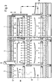
- a furnace for applying the method includes a number of successive heating stations or sections 1, 2, 3.
- a pair of laminated glass sheets is carried by a ring mould 11 into the first furnace section 1.
- the term "a pair of laminated glass sheets” can be replaced hereinafter by "a glass sheet”.
- Mould 11, together with its glass sheet, is advanced from one section to another by means of a mould wagon 9 provided with an end wall 9a which separates the successive sections from each other.
- a glass sheet is primarily heated with forced convection receiving its thermal energy from a bent glass sheet in the process of cooling in lower cooling sections 7, as described in more detail in the Applicant's patent US-4,986,842.
- the share of forced convection from the heating effect of a glass sheet is typically 90 % and the share of radiation is 10 %.
- the number of heating sections 1 based on the recovery of heat can be 3-6 and a glass sheet reaches therein a temperature of 230°C - 300°C prior to advancing into the following preheating section 2.
- the heating is partially effected by means of heating resistances 12 and partially by convection heat, coming through the floor and/or around the edges of carrier wagons 9 and delivered by glass sheets in the process of cooling in lower cooling sections 6.
- the share of radiation is e.g. 40 % and that of convection heating is 60 %.
- the number of preheating sections is typically 3-6.
- a glass sheet advances into a prebending section 3 as the glass temperature is e.g. about 530°C - 550°C.
- prebending sections 3 the temperature is raised by a few dozen degrees, which already results in slight bending of a glass sheet.
- a glass sheet is advanced into an actual bending section 4, wherein its temperature is raised e.g. to a temperature range of 590°C - 635°C.
- glass is highly sensitive to temperature variations and, thus, a change of even a few degrees in the temperature of a glass sheet has a major effect on its susceptibility to bending.
- the transfer of heat to glass is typically such that the share of radiation is 90 % and that of convection is 10 %.
- one embodiment of the invention includes a convection-air blasting pipe 13', which has been extended through the thermally insulated ceiling of the bending station 4 (and/or prebending station 3) and between heating resistances 12 to the proximity of the top surface of a glass sheet placed in the bending station.
- the distance between the bottom end of pipe 13 and the surface of a glass sheet can be within the range of 10 to 20 cm.
- the diameter of pipe 13 can be e.g. from 8 to 12 mm.
- pipe 13 is used to blow convection air very gently throughout the entire bending operation essentially over the mid-section of a glass sheet.
- the blowing rate is less than 0,1 l/s and typically within the range of 0,1 to 0,03 l/s.
- a very gentle blowing e.g. 0,01 l/s
- a pyrometer 14 is mounted on pipe 13 for measuring the temperature of bending glass.
- a control unit 15 is provided to switch the resistances 12 off during the course of bending such that the radiation heat distribution pattern changes in a predetermined manner during the bending.
- the control unit 15 can also be used for controlling valves 16 and 16' on the basis of temperature measurement.
- Valve 16 is a control valve for the regulation of flow rate and valve 16' is an on/off- valve.
- both valve types can be used separately or together for controlling the blowing time or rate. In a normal case, the blow control is not required at all for the duration of bending a single glass sheet but only when the type of glass sheet is changed.
- the on/off switching of a blast is required at the time a glass sheet is transferred from one station into another, so that the blasting or blowing would not be applied to the edge areas during a transfer. This is necessary since the focusing of a blast in any of the stations 2, 3 and/or 4 is used to make sure that a desired bending shape is attained.
- a typical case involves the use of a continuous and constant blow during the stay of glass at each station and the distribution of heat transfer is adjusted by adjusting the temperature distribution of a resistance field 12.
- the adjustment concerns primarily as to when and how many of the mid-section resistances are switched off at the final stage of heating in the bending section 4.
- a similar convection-air blasting system can also be arranged in preheating station 3.
- the creation of a necessary convection blasting requires a very low-power pump 17. Since the amount of air to be blown or blasted is very small, the blast air can be obtained directly from the room surrounding the furnace. Therefore, the air discharging from the pipe 13' is colder than the air in the furnace, this being the case also when the air in the pipe 13' is preheated (e.g. by the surrounding air in the furnace).
- a convection blasting of the invention serves to achieve, in addition to improved control over a bending area, also an increase in capacity since the convection blasting makes the bending operation substantially quicker. This is not actually a result of the increase of heat transfer effected by convection but it is due to the following facts: (1) the temperature difference between top and bottom glasses (or surfaces of a glass sheet) can be equalized, (2) the adjustment of resistances is not the only means for controlling the heat transfer distribution, and (3) in many cases, the total amount of radiation heat can be increased if desired.
- the location of a blasting spot as well as the blasting distance and the temperature of discharging air each have an effect on the shape a glass sheet is bending to.
- preheating sections 2 there develops a temperature difference of about 100°C between top and bottom glasses.
- This temperature difference causes the drawbacks mentioned in the introduction.
- the temperature of bottom glass can be e.g. 400°C.
- the temperature of a pair of glass sheets in the process of cooling on lower track 19 therebelow can be e.g. 500°C.
- the transfer of heat possessed by the glass on lower track 19 can be intensified by means of convection to the bottom glass of upper track 18 by blowing or blasting a small amount of air through the open floor of wagon 9 from pipes 13 fitted between the upper and lower tracks. There may be one or a plurality of blast pipes 13. It is possible to use e.g.
- Pipe 13 having a diameter of 20 mm and provided with 2,0 mm orifices 20 over the entire length at 50 mm intervals.
- the size of orifices 20 in the middle may also be different to those on the edges.
- the air to be delivered into pipes 13 can be compressed or blast air, which is preheated in a pipe system circulating inside a furnace or by means of a separate heater. Pipe 13 can also be branched.
- the top and bottom glass can be brought to an equal temperature prior to commencing the actual bending.
- Equal temperature or hemothermal glass facilitates rapid bending, since there is no need in the bending operation to wait for the bottom glass to heat up to a bending temperature.
- the glass finds its way better to a shape defined by a ring mould, especially in complex bends. Also the bending of a progressive sag is successfully effected with a short bending time. This is demonstrated by the test run curves shown in fig. 4.
- the deflection illustrated by the top curve is produced by using convection intensified according to the invention for raising the temperature of bottom glass.
- said pipes 13 are used for blasting convection air throughout the heating period, as a glass sheet is stationary in section 2.
- the blasting can be switched off, if necessary, in order not to apply the blast onto the edge portions.
- the method is capable of achieving an increase of about 30 % - 40 % in production capacity as compared to a similar type of furnace without blasting.
- blast pipes 13 as well as the size and disposition of orifices 20 included in pipes 13 can be used for such an effect that the temperature distribution of a glass sheet will be beneficial in view of a desired bending shape.
- the location of a blasting spot or the locations and distribution of the blasting spots have an effect on the shape a glass sheet is bending to.
- the blasting can be focused or distributed on the corner sections of a glass sheet, which require relatively sharp bends in multiple directions.
- the blowing spot of blast pipe 13 can be adapted to be maneuverable in vertical and/or horizontal direction.
- the manipulation of a blasting spot can be effected from outside the furnace mechanically by means of a suitable operating leverage.
- blasting is used below the mid-section of a glass sheet in the preheating sections 2, and the shape is also provided by means of a program controlling the distribution of radiation heat.
- the heating and bending section 4 there are additional resistances 12w on the side walls of the furnace below the level of the edge of the glass to be heated.
- the resistances 12w increase the general temperature of the lower portion of the heating and bending section 4. These additional resistances particularly aid the bending of the corners of the glass sheet.
- Fig. 9 shows a sag profile in the height direction of the glass sheet with the relation between the glass height H and the length h of the heated resistances 12a being about 2. (The resistances 12b are switched off during the sag bending). The resistances 12a with said relation 2 are still too long, i.e. the heated area extends too close to the lower and upper edge of the glass sheet, with the result that the sag profile is not progressive.
- Fig. 10 shows two different sag profiles with said relation being 2,2 (open dots) and 2,6 (black dots). The sag profile with said relation 2,6 is almost completely progressive.
- the resistances 12a above the middle section can be divided in three sections, which can be separately switched on and off (Fig. 8a).
- the resistances above the middle section can be made substantially shorter than the resistances (12, 12b) surrounding said middle section (Fig. 8).
- the resistances 12, 12b surrounding the middle section must extend substantially beyond the glass contour.
- Switching off of the resistances 12, 12b around the middle section resistances 12a takes place at the beginning and/or during the sag bending. This switching off of the resistances is controlled by the measured glass temperature.
Priority Applications (2)
| Application Number | Priority Date | Filing Date | Title |
|---|---|---|---|
| FI935664A FI94235C (fi) | 1993-06-21 | 1993-12-16 | Menetelmä lasilevyjen taivuttamiseksi |
| FI944438A FI944438A (fi) | 1993-09-28 | 1994-09-26 | Menetelmä ja uuni lasilevyjen taivuttamiseksi |
Applications Claiming Priority (6)
| Application Number | Priority Date | Filing Date | Title |
|---|---|---|---|
| FI924666A FI91521C (fi) | 1992-10-15 | 1992-10-15 | Menetelmä lasilevyjen taivuttamiseksi |
| FI924666 | 1992-10-15 | ||
| FI932861A FI94233C (fi) | 1993-06-21 | 1993-06-21 | Menetelmä ja uuni lasilevyjen taivuttamiseksi |
| FI932861 | 1993-06-21 | ||
| FI933318 | 1993-07-23 | ||
| FI933318A FI94234C (fi) | 1993-06-21 | 1993-07-23 | Menetelmä laminoitujen lasilevyjen taivuttamiseksi |
Publications (2)
| Publication Number | Publication Date |
|---|---|
| EP0592862A1 true EP0592862A1 (de) | 1994-04-20 |
| EP0592862B1 EP0592862B1 (de) | 1997-03-12 |
Family
ID=27241529
Family Applications (1)
| Application Number | Title | Priority Date | Filing Date |
|---|---|---|---|
| EP93115632A Expired - Lifetime EP0592862B1 (de) | 1992-10-15 | 1993-09-28 | Verfahren und Ofen zum Biegen von Glastafeln |
Country Status (8)
| Country | Link |
|---|---|
| US (1) | US5437704A (de) |
| EP (1) | EP0592862B1 (de) |
| JP (1) | JP3718532B2 (de) |
| CN (1) | CN1046255C (de) |
| AT (1) | ATE149978T1 (de) |
| AU (1) | AU666043B2 (de) |
| CA (1) | CA2107841C (de) |
| DE (1) | DE69308715T2 (de) |
Cited By (14)
| Publication number | Priority date | Publication date | Assignee | Title |
|---|---|---|---|---|
| EP0659697A2 (de) * | 1993-12-23 | 1995-06-28 | Pilkington Glass Limited | Glasbiegeofen |
| EP0721922A1 (de) * | 1995-01-10 | 1996-07-17 | Tamglass Engineering Oy | Verfahren zum Erwärmen von Glastafeln, die getempert oder durch Wärme gehärtet werden sollen |
| US5669952A (en) * | 1994-10-14 | 1997-09-23 | Ppg Industries, Inc. | Pressure forming of glass sheets |
| WO1998001398A1 (en) * | 1996-07-05 | 1998-01-15 | Ianua S.P.A. | Furnace for heat treatments of glass sheets |
| EP0937687A2 (de) * | 1998-02-18 | 1999-08-25 | Tamglass Ltd. Oy | Verfahren und Vorrichtung zum lokalen Erhitzen von Glastafeln in einem Temperofen |
| WO2000029339A1 (en) * | 1998-11-12 | 2000-05-25 | Glassrobots Oy | Arrangement in a glass bending oven |
| WO2000029340A1 (en) * | 1998-11-12 | 2000-05-25 | Glassrobots Oy | Arrangement in a glass bending oven |
| WO2001023310A1 (en) * | 1999-09-27 | 2001-04-05 | Asahi Glass Company, Limited | Bending apparatus for glass sheet and method of bending glass sheet |
| FR2828191A1 (fr) * | 2001-08-06 | 2003-02-07 | Saint Gobain | Procede de traitement d'un vitrage feuillete et application |
| EP1371616A1 (de) * | 2002-06-12 | 2003-12-17 | Tamglass Ltd. Oy | Vorrichtung zum Biegen und Vorspannen von Glascheiben |
| EP1391432A1 (de) * | 2002-06-12 | 2004-02-25 | Tamglass Ltd. Oy | Vorrichtung zum Biegen und Kühlen von Glasscheiben |
| WO2013078037A1 (en) * | 2011-11-23 | 2013-05-30 | Corning Incorporated | Method and system for making glass articles |
| RU2550611C1 (ru) * | 2014-03-05 | 2015-05-10 | Закрытое акционерное общество "МАКРОМЕР" | Установка для изгибания листового стекла |
| EP3022159B1 (de) * | 2013-07-16 | 2019-03-20 | Corning Incorporated | Vorrichtung und verfahren zum biegen dünnes glas |
Families Citing this family (31)
| Publication number | Priority date | Publication date | Assignee | Title |
|---|---|---|---|---|
| FI92816C (fi) * | 1993-04-23 | 1995-01-10 | Tamglass Eng Oy | Menetelmä ja uunilaitteisto rengasmuotilla kannatetun lasilevyn taivuttamiseksi ja karkaisemiseksi |
| GB9416893D0 (en) * | 1994-08-20 | 1994-10-12 | Triplex Safety Glass Co | Heating and bending glass sheets |
| AU702965B2 (en) * | 1996-02-28 | 1999-03-11 | Diniben Pty Ltd | A method of bending glass sheets |
| FI109199B (fi) * | 2001-02-28 | 2002-06-14 | Tamglass Ltd Oy | Laite lasilevyjen taivuttamiseksi |
| FI20035065A (fi) * | 2003-05-14 | 2004-11-15 | Tamglass Ltd Oy | Menetelmä ja uuni lasilevyjen taivuttamiseksi |
| CN101309873B (zh) * | 2005-11-18 | 2011-11-09 | Hoya株式会社 | 成形品的制造方法、成形模型及其制造方法 |
| KR20130020846A (ko) * | 2005-11-18 | 2013-02-28 | 호야 가부시키가이샤 | 성형품의 제조 방법, 유리 소재, 및 유리 소재와 성형형의 면 형상 결정 방법 |
| US8197727B2 (en) * | 2005-11-30 | 2012-06-12 | Hoya Corporation | Method of manufacturing formed article, covering member, and forming apparatus comprising the same |
| DE102006035555A1 (de) * | 2006-07-27 | 2008-01-31 | Eliog-Kelvitherm Industrieofenbau Gmbh | Anordnung und Verfahren zur Verformung von Glasscheiben |
| JP5393664B2 (ja) * | 2008-05-30 | 2014-01-22 | Hoya株式会社 | レンズ用鋳型の製造方法 |
| EP2402132A4 (de) * | 2009-02-27 | 2014-10-15 | Hoya Corp | Vorrichtung zur herstellung einer form für eine linse und verfahren zur herstellung eines brillenglases |
| CN102414000A (zh) * | 2009-02-27 | 2012-04-11 | Hoya株式会社 | 透镜用铸模的制造方法及眼镜透镜的制造方法 |
| US8528366B2 (en) * | 2011-12-22 | 2013-09-10 | Sunpower Corporation | Heat-regulating glass bending apparatus and method |
| CN102757169B (zh) * | 2012-07-20 | 2014-08-20 | 福耀玻璃工业集团股份有限公司 | 一种用于弯曲玻璃板的弯曲炉和方法 |
| CN103803781B (zh) * | 2012-11-09 | 2016-04-13 | 信义汽车玻璃(深圳)有限公司 | 一种玻璃连续热弯炉 |
| US9446977B2 (en) * | 2012-12-10 | 2016-09-20 | Corning Incorporated | Method and system for making a glass article with uniform mold temperature |
| US10526232B2 (en) | 2013-05-30 | 2020-01-07 | Ppg Industries Ohio, Inc. | Microwave heating glass bending process |
| CN103771693A (zh) * | 2014-01-07 | 2014-05-07 | 珠海华尚汽车玻璃工业有限公司 | 一种新型大巴玻璃数控连续烘弯炉 |
| JP6383979B2 (ja) * | 2014-09-05 | 2018-09-05 | Agc株式会社 | 湾曲ガラス板の製造方法及びその湾曲ガラス板を用いて製造された合わせガラス |
| CN107848864B (zh) * | 2015-08-06 | 2021-01-01 | Ppg工业俄亥俄公司 | 微波加热玻璃弯曲方法和装置 |
| CN107324641A (zh) * | 2016-04-29 | 2017-11-07 | 深圳市尊泰自动化设备有限公司 | 一种热弯玻璃加工设备 |
| MX2019008998A (es) | 2017-01-30 | 2019-10-09 | Saint Gobain | Metodo y dispositivo para doblar un cristal de vidrio. |
| CN107162399B (zh) * | 2017-07-19 | 2020-07-03 | 安徽云融信息技术有限公司 | 一种玻璃加工系统及加工方法 |
| CN107352780B (zh) * | 2017-07-19 | 2021-05-25 | 安徽云融信息技术有限公司 | 一种玻璃加工装置及加工方法 |
| DE102018204476A1 (de) * | 2018-03-23 | 2019-09-26 | Fraunhofer-Gesellschaft zur Förderung der angewandten Forschung e.V. | Vorrichtung mit einem Ofen und Verfahren zu deren Verwendung |
| TWI660920B (zh) * | 2018-06-25 | 2019-06-01 | 海納光電股份有限公司 | 非接觸成型裝置及方法 |
| JP7012943B2 (ja) * | 2018-09-06 | 2022-01-31 | Agc株式会社 | 車両用ガラスの成形方法 |
| CN109297186A (zh) * | 2018-10-23 | 2019-02-01 | 北京百恒达石油技术有限公司 | 一种油田专用的火筒式直接加热炉 |
| WO2020136909A1 (ja) * | 2018-12-28 | 2020-07-02 | 株式会社三光精衡所 | 熱塑性板の曲げ加工方法、及び加工治具、及び凹面熱塑性板 |
| CN110253729A (zh) * | 2019-06-03 | 2019-09-20 | 陈培鑫 | 一种陶瓷薄板的二次加工方法 |
| CN114646218B (zh) * | 2022-05-19 | 2022-10-25 | 蒙娜丽莎集团股份有限公司 | 岩板热弯炉及对岩板进行热弯处理的方法 |
Citations (7)
| Publication number | Priority date | Publication date | Assignee | Title |
|---|---|---|---|---|
| US2967378A (en) * | 1958-12-09 | 1961-01-10 | Pittsburgh Plate Glass Co | Method and apparatus for bending glass |
| US4497645A (en) * | 1983-07-25 | 1985-02-05 | O/Y Kyro A/B Tamglass | Method of and furnace assembly for bending glass sheets |
| US4755204A (en) * | 1986-02-20 | 1988-07-05 | Pilkington Brothers P.L.C. | Manufacture of curved glass sheets |
| EP0370310A1 (de) * | 1988-11-24 | 1990-05-30 | Tamglass Engineering Oy | Verfahren und Vorrichtung zur Vermeidung von Verbiegungen der Tragschienen der Einsatzwagen in einem Glasscheiben-Biegeofen |
| US4986842A (en) * | 1988-11-24 | 1991-01-22 | Tamglass Oy | Heat transfer method in a glass sheet bending furnace and bending furnace |
| US5009691A (en) * | 1989-03-24 | 1991-04-23 | Central Glass Company, Limited | Method of bending glass plate |
| EP0486952A2 (de) * | 1990-11-19 | 1992-05-27 | Tamglass Engineering Oy | Verfahren zum Erhitzen und Biegen einer Glasscheibe |
Family Cites Families (4)
| Publication number | Priority date | Publication date | Assignee | Title |
|---|---|---|---|---|
| US3001328A (en) * | 1958-07-25 | 1961-09-26 | Pittsburgh Plate Glass Co | Glass bending lehrs and conveyors therefor |
| US4986848A (en) * | 1988-01-28 | 1991-01-22 | Hitachi Chemical Company, Ltd. | Catalyst for electroless plating |
| FR2658808B1 (fr) * | 1990-02-21 | 1993-05-14 | Saint Gobain Vitrage Int | Four de bombage de feuilles de verre par effondrement sur un cadre de bombage et son application a la realisation de vitrages de forme complexe. |
| FI86295C (fi) * | 1990-09-21 | 1992-08-10 | Tamglass Oy | Foerfarande och anordning foer boejning av en glasskiva. |
-
1993
- 1993-09-28 AT AT93115632T patent/ATE149978T1/de active
- 1993-09-28 DE DE69308715T patent/DE69308715T2/de not_active Expired - Fee Related
- 1993-09-28 EP EP93115632A patent/EP0592862B1/de not_active Expired - Lifetime
- 1993-10-05 AU AU48795/93A patent/AU666043B2/en not_active Ceased
- 1993-10-06 CA CA002107841A patent/CA2107841C/en not_active Expired - Fee Related
- 1993-10-06 US US08/132,184 patent/US5437704A/en not_active Expired - Lifetime
- 1993-10-14 JP JP28038993A patent/JP3718532B2/ja not_active Expired - Fee Related
- 1993-10-15 CN CN93118945A patent/CN1046255C/zh not_active Expired - Fee Related
Patent Citations (7)
| Publication number | Priority date | Publication date | Assignee | Title |
|---|---|---|---|---|
| US2967378A (en) * | 1958-12-09 | 1961-01-10 | Pittsburgh Plate Glass Co | Method and apparatus for bending glass |
| US4497645A (en) * | 1983-07-25 | 1985-02-05 | O/Y Kyro A/B Tamglass | Method of and furnace assembly for bending glass sheets |
| US4755204A (en) * | 1986-02-20 | 1988-07-05 | Pilkington Brothers P.L.C. | Manufacture of curved glass sheets |
| EP0370310A1 (de) * | 1988-11-24 | 1990-05-30 | Tamglass Engineering Oy | Verfahren und Vorrichtung zur Vermeidung von Verbiegungen der Tragschienen der Einsatzwagen in einem Glasscheiben-Biegeofen |
| US4986842A (en) * | 1988-11-24 | 1991-01-22 | Tamglass Oy | Heat transfer method in a glass sheet bending furnace and bending furnace |
| US5009691A (en) * | 1989-03-24 | 1991-04-23 | Central Glass Company, Limited | Method of bending glass plate |
| EP0486952A2 (de) * | 1990-11-19 | 1992-05-27 | Tamglass Engineering Oy | Verfahren zum Erhitzen und Biegen einer Glasscheibe |
Cited By (28)
| Publication number | Priority date | Publication date | Assignee | Title |
|---|---|---|---|---|
| EP0659697A3 (de) * | 1993-12-23 | 1996-01-10 | Pilkington Glass Ltd | Glasbiegeofen. |
| US5656052A (en) * | 1993-12-23 | 1997-08-12 | Pilkington Glass Limited | Apparatus for and method of heating and bending glass sheet |
| EP0659697A2 (de) * | 1993-12-23 | 1995-06-28 | Pilkington Glass Limited | Glasbiegeofen |
| US5669952A (en) * | 1994-10-14 | 1997-09-23 | Ppg Industries, Inc. | Pressure forming of glass sheets |
| US5769919A (en) * | 1994-10-14 | 1998-06-23 | Ppg Industries, Inc. | Pressure forming of glass sheets |
| AU700657B2 (en) * | 1995-01-10 | 1999-01-14 | Tamglass Ltd. Oy | Method for heating glass sheets to be tempered or heat- strengthened |
| EP0721922A1 (de) * | 1995-01-10 | 1996-07-17 | Tamglass Engineering Oy | Verfahren zum Erwärmen von Glastafeln, die getempert oder durch Wärme gehärtet werden sollen |
| US6470711B1 (en) | 1996-07-05 | 2002-10-29 | Ianua S P A | Furnace for heat treatments of glass sheets |
| WO1998001398A1 (en) * | 1996-07-05 | 1998-01-15 | Ianua S.P.A. | Furnace for heat treatments of glass sheets |
| EP0937687A3 (de) * | 1998-02-18 | 2000-03-01 | Tamglass Ltd. Oy | Verfahren und Vorrichtung zum lokalen Erhitzen von Glastafeln in einem Temperofen |
| US6064040A (en) * | 1998-02-18 | 2000-05-16 | Tamglass Ltd Oy | Method and apparatus for the localization of heating in a tempering furnace for glass panels |
| EP0937687A2 (de) * | 1998-02-18 | 1999-08-25 | Tamglass Ltd. Oy | Verfahren und Vorrichtung zum lokalen Erhitzen von Glastafeln in einem Temperofen |
| WO2000029339A1 (en) * | 1998-11-12 | 2000-05-25 | Glassrobots Oy | Arrangement in a glass bending oven |
| WO2000029340A1 (en) * | 1998-11-12 | 2000-05-25 | Glassrobots Oy | Arrangement in a glass bending oven |
| US6578384B1 (en) | 1998-11-12 | 2003-06-17 | Glassrobots Oy | Arrangement in a glass bending oven |
| US7331198B1 (en) | 1999-09-27 | 2008-02-19 | Asahi Glass Company, Limited | Bending apparatus for a glass sheet |
| WO2001023310A1 (en) * | 1999-09-27 | 2001-04-05 | Asahi Glass Company, Limited | Bending apparatus for glass sheet and method of bending glass sheet |
| FR2828191A1 (fr) * | 2001-08-06 | 2003-02-07 | Saint Gobain | Procede de traitement d'un vitrage feuillete et application |
| WO2003014033A1 (fr) * | 2001-08-06 | 2003-02-20 | Saint-Gobain Glass France | Procede de traitement d'un vitrage feuillete et application |
| EP1371616A1 (de) * | 2002-06-12 | 2003-12-17 | Tamglass Ltd. Oy | Vorrichtung zum Biegen und Vorspannen von Glascheiben |
| US7155939B2 (en) | 2002-06-12 | 2007-01-02 | Tamglass Ltd. Oy | Apparatus for bending glass panels |
| EP1391432A1 (de) * | 2002-06-12 | 2004-02-25 | Tamglass Ltd. Oy | Vorrichtung zum Biegen und Kühlen von Glasscheiben |
| US7389655B2 (en) | 2002-06-12 | 2008-06-24 | Tamglass Ltd. Oy | Apparatus for bending and tempering glass panels |
| WO2013078037A1 (en) * | 2011-11-23 | 2013-05-30 | Corning Incorporated | Method and system for making glass articles |
| US8776550B2 (en) | 2011-11-23 | 2014-07-15 | Corning Incorporated | Method and system for making glass articles |
| US9469561B2 (en) | 2011-11-23 | 2016-10-18 | Corning Incorporated | Method and system for making glass articles |
| EP3022159B1 (de) * | 2013-07-16 | 2019-03-20 | Corning Incorporated | Vorrichtung und verfahren zum biegen dünnes glas |
| RU2550611C1 (ru) * | 2014-03-05 | 2015-05-10 | Закрытое акционерное общество "МАКРОМЕР" | Установка для изгибания листового стекла |
Also Published As
| Publication number | Publication date |
|---|---|
| DE69308715D1 (de) | 1997-04-17 |
| CN1088550A (zh) | 1994-06-29 |
| CA2107841A1 (en) | 1994-04-16 |
| CN1046255C (zh) | 1999-11-10 |
| DE69308715T2 (de) | 1997-06-19 |
| AU4879593A (en) | 1994-04-28 |
| EP0592862B1 (de) | 1997-03-12 |
| JPH07300328A (ja) | 1995-11-14 |
| ATE149978T1 (de) | 1997-03-15 |
| AU666043B2 (en) | 1996-01-25 |
| US5437704A (en) | 1995-08-01 |
| CA2107841C (en) | 2004-11-23 |
| JP3718532B2 (ja) | 2005-11-24 |
Similar Documents
| Publication | Publication Date | Title |
|---|---|---|
| US5437704A (en) | Method and furnace for bending glass sheets | |
| US5306324A (en) | Method and apparatus for bending and tempering a glass sheet | |
| US5472469A (en) | Method of bending glass sheets | |
| US4277276A (en) | Method and apparatus for shaping glass sheets using deformable vacuum mold | |
| US4285715A (en) | Cycle of mold movement while press bending glass sheets | |
| US6983624B2 (en) | Apparatus for bending glass panels | |
| CN1088044C (zh) | 用于加热欲回火或热强化的玻璃板的方法 | |
| CA2373332A1 (en) | Method and apparatus for heating glass panels in a tempering furnace equipped with rollers | |
| EP0621244A1 (de) | Verfahren und Vorrichtung zum Biegen und Härten einer Glasscheibe getragen auf einer Ringform | |
| US4252552A (en) | Shaping glass sheets using molds of different shapes | |
| EP1626938B1 (de) | Verfahren und ofen zum biegen von glasscheiben | |
| JPH035330A (ja) | 自動車用焼入れバルジングガラスの製造方法及び装置 | |
| US3387962A (en) | Method of bending and annealing glass sheets with supplemental cooling of hotter areas of the glass | |
| JPS6112854B2 (de) | ||
| US5078770A (en) | Method for bending difficult bending shapes such as an s-shape in a glass sheet | |
| US5100454A (en) | Process and apparatus for obtaining cambered glass sheets | |
| KR100186935B1 (ko) | 유리의 연속 절곡장치 | |
| US3862828A (en) | Controlling glass sheet furnace & temperatures | |
| US5268016A (en) | Apparatus for obtaining cambered and/or glazed glass sheets | |
| CA1150053A (en) | Shaping glass sheets using molds of different shapes | |
| FI94233C (fi) | Menetelmä ja uuni lasilevyjen taivuttamiseksi | |
| FI91245B (fi) | Uunilaitteisto lasilevyn taivuttamiseksi ja karkaisemiseksi | |
| FI94234B (fi) | Menetelmä laminoitujen lasilevyjen taivuttamiseksi |
Legal Events
| Date | Code | Title | Description |
|---|---|---|---|
| PUAI | Public reference made under article 153(3) epc to a published international application that has entered the european phase |
Free format text: ORIGINAL CODE: 0009012 |
|
| AK | Designated contracting states |
Kind code of ref document: A1 Designated state(s): AT BE CH DE ES FR GB IT LI NL SE |
|
| 17P | Request for examination filed |
Effective date: 19940531 |
|
| 17Q | First examination report despatched |
Effective date: 19940930 |
|
| GRAG | Despatch of communication of intention to grant |
Free format text: ORIGINAL CODE: EPIDOS AGRA |
|
| GRAH | Despatch of communication of intention to grant a patent |
Free format text: ORIGINAL CODE: EPIDOS IGRA |
|
| GRAH | Despatch of communication of intention to grant a patent |
Free format text: ORIGINAL CODE: EPIDOS IGRA |
|
| GRAA | (expected) grant |
Free format text: ORIGINAL CODE: 0009210 |
|
| AK | Designated contracting states |
Kind code of ref document: B1 Designated state(s): AT BE CH DE ES FR GB IT LI NL SE |
|
| PG25 | Lapsed in a contracting state [announced via postgrant information from national office to epo] |
Ref country code: NL Free format text: LAPSE BECAUSE OF FAILURE TO SUBMIT A TRANSLATION OF THE DESCRIPTION OR TO PAY THE FEE WITHIN THE PRESCRIBED TIME-LIMIT Effective date: 19970312 Ref country code: ES Free format text: THE PATENT HAS BEEN ANNULLED BY A DECISION OF A NATIONAL AUTHORITY Effective date: 19970312 Ref country code: BE Effective date: 19970312 Ref country code: AT Effective date: 19970312 |
|
| REF | Corresponds to: |
Ref document number: 149978 Country of ref document: AT Date of ref document: 19970315 Kind code of ref document: T |
|
| REG | Reference to a national code |
Ref country code: CH Ref legal event code: NV Representative=s name: DIPL.-ING. HORST QUEHL PATENTANWALT Ref country code: CH Ref legal event code: EP |
|
| REF | Corresponds to: |
Ref document number: 69308715 Country of ref document: DE Date of ref document: 19970417 |
|
| ITF | It: translation for a ep patent filed |
Owner name: JACOBACCI & PERANI S.P.A. |
|
| ET | Fr: translation filed | ||
| PG25 | Lapsed in a contracting state [announced via postgrant information from national office to epo] |
Ref country code: SE Effective date: 19970612 |
|
| NLV1 | Nl: lapsed or annulled due to failure to fulfill the requirements of art. 29p and 29m of the patents act | ||
| PG25 | Lapsed in a contracting state [announced via postgrant information from national office to epo] |
Ref country code: LI Free format text: LAPSE BECAUSE OF NON-PAYMENT OF DUE FEES Effective date: 19970930 Ref country code: CH Free format text: LAPSE BECAUSE OF NON-PAYMENT OF DUE FEES Effective date: 19970930 |
|
| PLBE | No opposition filed within time limit |
Free format text: ORIGINAL CODE: 0009261 |
|
| STAA | Information on the status of an ep patent application or granted ep patent |
Free format text: STATUS: NO OPPOSITION FILED WITHIN TIME LIMIT |
|
| 26N | No opposition filed | ||
| REG | Reference to a national code |
Ref country code: CH Ref legal event code: PL |
|
| REG | Reference to a national code |
Ref country code: GB Ref legal event code: IF02 |
|
| REG | Reference to a national code |
Ref country code: FR Ref legal event code: CD |
|
| PGFP | Annual fee paid to national office [announced via postgrant information from national office to epo] |
Ref country code: GB Payment date: 20080822 Year of fee payment: 16 |
|
| PGFP | Annual fee paid to national office [announced via postgrant information from national office to epo] |
Ref country code: DE Payment date: 20080829 Year of fee payment: 16 |
|
| PGFP | Annual fee paid to national office [announced via postgrant information from national office to epo] |
Ref country code: IT Payment date: 20090923 Year of fee payment: 17 |
|
| GBPC | Gb: european patent ceased through non-payment of renewal fee |
Effective date: 20090928 |
|
| PG25 | Lapsed in a contracting state [announced via postgrant information from national office to epo] |
Ref country code: DE Free format text: LAPSE BECAUSE OF NON-PAYMENT OF DUE FEES Effective date: 20100401 |
|
| PG25 | Lapsed in a contracting state [announced via postgrant information from national office to epo] |
Ref country code: GB Free format text: LAPSE BECAUSE OF NON-PAYMENT OF DUE FEES Effective date: 20090928 |
|
| PG25 | Lapsed in a contracting state [announced via postgrant information from national office to epo] |
Ref country code: IT Free format text: LAPSE BECAUSE OF NON-PAYMENT OF DUE FEES Effective date: 20100928 |
|
| REG | Reference to a national code |
Ref country code: FR Ref legal event code: ST Effective date: 20110531 |
|
| PG25 | Lapsed in a contracting state [announced via postgrant information from national office to epo] |
Ref country code: FR Free format text: LAPSE BECAUSE OF NON-PAYMENT OF DUE FEES Effective date: 20100930 |
|
| PGFP | Annual fee paid to national office [announced via postgrant information from national office to epo] |
Ref country code: FR Payment date: 20091001 Year of fee payment: 17 |