EP0592737A1 - Horizontal cyclone separator for a fluidized bed reactor - Google Patents
Horizontal cyclone separator for a fluidized bed reactor Download PDFInfo
- Publication number
- EP0592737A1 EP0592737A1 EP92309357A EP92309357A EP0592737A1 EP 0592737 A1 EP0592737 A1 EP 0592737A1 EP 92309357 A EP92309357 A EP 92309357A EP 92309357 A EP92309357 A EP 92309357A EP 0592737 A1 EP0592737 A1 EP 0592737A1
- Authority
- EP
- European Patent Office
- Prior art keywords
- chamber
- separator
- walls
- tube
- mixture
- Prior art date
- Legal status (The legal status is an assumption and is not a legal conclusion. Google has not performed a legal analysis and makes no representation as to the accuracy of the status listed.)
- Withdrawn
Links
- 239000007789 gas Substances 0.000 claims abstract description 42
- 239000000203 mixture Substances 0.000 claims abstract description 28
- 238000011084 recovery Methods 0.000 claims abstract description 26
- 239000002245 particle Substances 0.000 claims abstract description 24
- 239000000446 fuel Substances 0.000 claims abstract description 21
- 239000011236 particulate material Substances 0.000 claims abstract description 12
- 238000005192 partition Methods 0.000 claims description 22
- 239000000463 material Substances 0.000 claims description 9
- 238000007599 discharging Methods 0.000 claims description 6
- 239000012809 cooling fluid Substances 0.000 claims 1
- 239000013529 heat transfer fluid Substances 0.000 claims 1
- 239000011819 refractory material Substances 0.000 claims 1
- 238000002485 combustion reaction Methods 0.000 abstract description 21
- 239000007787 solid Substances 0.000 abstract description 17
- 238000002309 gasification Methods 0.000 abstract description 2
- 239000012530 fluid Substances 0.000 description 15
- XLYOFNOQVPJJNP-UHFFFAOYSA-N water Substances O XLYOFNOQVPJJNP-UHFFFAOYSA-N 0.000 description 12
- 230000005587 bubbling Effects 0.000 description 8
- 239000003245 coal Substances 0.000 description 6
- MWUXSHHQAYIFBG-UHFFFAOYSA-N nitrogen oxide Inorganic materials O=[N] MWUXSHHQAYIFBG-UHFFFAOYSA-N 0.000 description 6
- NINIDFKCEFEMDL-UHFFFAOYSA-N Sulfur Chemical compound [S] NINIDFKCEFEMDL-UHFFFAOYSA-N 0.000 description 5
- 238000000034 method Methods 0.000 description 5
- 238000000926 separation method Methods 0.000 description 5
- 229910052717 sulfur Inorganic materials 0.000 description 5
- 239000011593 sulfur Substances 0.000 description 5
- 239000003463 adsorbent Substances 0.000 description 4
- 230000015572 biosynthetic process Effects 0.000 description 2
- 239000000567 combustion gas Substances 0.000 description 2
- 239000010419 fine particle Substances 0.000 description 2
- 230000008569 process Effects 0.000 description 2
- 238000004064 recycling Methods 0.000 description 2
- 239000002594 sorbent Substances 0.000 description 2
- 238000001179 sorption measurement Methods 0.000 description 2
- 235000019738 Limestone Nutrition 0.000 description 1
- 230000009471 action Effects 0.000 description 1
- 238000004891 communication Methods 0.000 description 1
- 150000001875 compounds Chemical class 0.000 description 1
- 238000010276 construction Methods 0.000 description 1
- 238000001816 cooling Methods 0.000 description 1
- 230000003247 decreasing effect Effects 0.000 description 1
- 239000010459 dolomite Substances 0.000 description 1
- 229910000514 dolomite Inorganic materials 0.000 description 1
- 238000001035 drying Methods 0.000 description 1
- 230000005611 electricity Effects 0.000 description 1
- 239000003344 environmental pollutant Substances 0.000 description 1
- 239000002803 fossil fuel Substances 0.000 description 1
- 230000005484 gravity Effects 0.000 description 1
- 238000009413 insulation Methods 0.000 description 1
- 239000006028 limestone Substances 0.000 description 1
- 239000008239 natural water Substances 0.000 description 1
- 231100000719 pollutant Toxicity 0.000 description 1
- 230000001105 regulatory effect Effects 0.000 description 1
- 229920006395 saturated elastomer Polymers 0.000 description 1
- 238000007789 sealing Methods 0.000 description 1
- 239000002915 spent fuel radioactive waste Substances 0.000 description 1
Images
Classifications
-
- F—MECHANICAL ENGINEERING; LIGHTING; HEATING; WEAPONS; BLASTING
- F23—COMBUSTION APPARATUS; COMBUSTION PROCESSES
- F23J—REMOVAL OR TREATMENT OF COMBUSTION PRODUCTS OR COMBUSTION RESIDUES; FLUES
- F23J15/00—Arrangements of devices for treating smoke or fumes
- F23J15/02—Arrangements of devices for treating smoke or fumes of purifiers, e.g. for removing noxious material
- F23J15/022—Arrangements of devices for treating smoke or fumes of purifiers, e.g. for removing noxious material for removing solid particulate material from the gasflow
- F23J15/027—Arrangements of devices for treating smoke or fumes of purifiers, e.g. for removing noxious material for removing solid particulate material from the gasflow using cyclone separators
-
- B—PERFORMING OPERATIONS; TRANSPORTING
- B01—PHYSICAL OR CHEMICAL PROCESSES OR APPARATUS IN GENERAL
- B01D—SEPARATION
- B01D45/00—Separating dispersed particles from gases or vapours by gravity, inertia, or centrifugal forces
- B01D45/12—Separating dispersed particles from gases or vapours by gravity, inertia, or centrifugal forces by centrifugal forces
-
- B—PERFORMING OPERATIONS; TRANSPORTING
- B01—PHYSICAL OR CHEMICAL PROCESSES OR APPARATUS IN GENERAL
- B01J—CHEMICAL OR PHYSICAL PROCESSES, e.g. CATALYSIS OR COLLOID CHEMISTRY; THEIR RELEVANT APPARATUS
- B01J8/00—Chemical or physical processes in general, conducted in the presence of fluids and solid particles; Apparatus for such processes
- B01J8/005—Separating solid material from the gas/liquid stream
-
- B—PERFORMING OPERATIONS; TRANSPORTING
- B04—CENTRIFUGAL APPARATUS OR MACHINES FOR CARRYING-OUT PHYSICAL OR CHEMICAL PROCESSES
- B04C—APPARATUS USING FREE VORTEX FLOW, e.g. CYCLONES
- B04C1/00—Apparatus in which the main direction of flow follows a flat spiral ; so-called flat cyclones or vortex chambers
-
- B—PERFORMING OPERATIONS; TRANSPORTING
- B04—CENTRIFUGAL APPARATUS OR MACHINES FOR CARRYING-OUT PHYSICAL OR CHEMICAL PROCESSES
- B04C—APPARATUS USING FREE VORTEX FLOW, e.g. CYCLONES
- B04C3/00—Apparatus in which the axial direction of the vortex flow following a screw-thread type line remains unchanged ; Devices in which one of the two discharge ducts returns centrally through the vortex chamber, a reverse-flow vortex being prevented by bulkheads in the central discharge duct
- B04C3/02—Apparatus in which the axial direction of the vortex flow following a screw-thread type line remains unchanged ; Devices in which one of the two discharge ducts returns centrally through the vortex chamber, a reverse-flow vortex being prevented by bulkheads in the central discharge duct with heating or cooling, e.g. quenching, means
-
- B—PERFORMING OPERATIONS; TRANSPORTING
- B04—CENTRIFUGAL APPARATUS OR MACHINES FOR CARRYING-OUT PHYSICAL OR CHEMICAL PROCESSES
- B04C—APPARATUS USING FREE VORTEX FLOW, e.g. CYCLONES
- B04C5/00—Apparatus in which the axial direction of the vortex is reversed
-
- B—PERFORMING OPERATIONS; TRANSPORTING
- B04—CENTRIFUGAL APPARATUS OR MACHINES FOR CARRYING-OUT PHYSICAL OR CHEMICAL PROCESSES
- B04C—APPARATUS USING FREE VORTEX FLOW, e.g. CYCLONES
- B04C5/00—Apparatus in which the axial direction of the vortex is reversed
- B04C5/12—Construction of the overflow ducting, e.g. diffusing or spiral exits
- B04C5/13—Construction of the overflow ducting, e.g. diffusing or spiral exits formed as a vortex finder and extending into the vortex chamber; Discharge from vortex finder otherwise than at the top of the cyclone; Devices for controlling the overflow
-
- B—PERFORMING OPERATIONS; TRANSPORTING
- B04—CENTRIFUGAL APPARATUS OR MACHINES FOR CARRYING-OUT PHYSICAL OR CHEMICAL PROCESSES
- B04C—APPARATUS USING FREE VORTEX FLOW, e.g. CYCLONES
- B04C5/00—Apparatus in which the axial direction of the vortex is reversed
- B04C5/14—Construction of the underflow ducting; Apex constructions; Discharge arrangements ; discharge through sidewall provided with a few slits or perforations
-
- B—PERFORMING OPERATIONS; TRANSPORTING
- B04—CENTRIFUGAL APPARATUS OR MACHINES FOR CARRYING-OUT PHYSICAL OR CHEMICAL PROCESSES
- B04C—APPARATUS USING FREE VORTEX FLOW, e.g. CYCLONES
- B04C5/00—Apparatus in which the axial direction of the vortex is reversed
- B04C5/20—Apparatus in which the axial direction of the vortex is reversed with heating or cooling, e.g. quenching, means
-
- F—MECHANICAL ENGINEERING; LIGHTING; HEATING; WEAPONS; BLASTING
- F22—STEAM GENERATION
- F22B—METHODS OF STEAM GENERATION; STEAM BOILERS
- F22B31/00—Modifications of boiler construction, or of tube systems, dependent on installation of combustion apparatus; Arrangements of dispositions of combustion apparatus
- F22B31/0007—Modifications of boiler construction, or of tube systems, dependent on installation of combustion apparatus; Arrangements of dispositions of combustion apparatus with combustion in a fluidized bed
- F22B31/0084—Modifications of boiler construction, or of tube systems, dependent on installation of combustion apparatus; Arrangements of dispositions of combustion apparatus with combustion in a fluidized bed with recirculation of separated solids or with cooling of the bed particles outside the combustion bed
-
- F—MECHANICAL ENGINEERING; LIGHTING; HEATING; WEAPONS; BLASTING
- F23—COMBUSTION APPARATUS; COMBUSTION PROCESSES
- F23C—METHODS OR APPARATUS FOR COMBUSTION USING FLUID FUEL OR SOLID FUEL SUSPENDED IN A CARRIER GAS OR AIR
- F23C10/00—Fluidised bed combustion apparatus
- F23C10/02—Fluidised bed combustion apparatus with means specially adapted for achieving or promoting a circulating movement of particles within the bed or for a recirculation of particles entrained from the bed
- F23C10/04—Fluidised bed combustion apparatus with means specially adapted for achieving or promoting a circulating movement of particles within the bed or for a recirculation of particles entrained from the bed the particles being circulated to a section, e.g. a heat-exchange section or a return duct, at least partially shielded from the combustion zone, before being reintroduced into the combustion zone
- F23C10/08—Fluidised bed combustion apparatus with means specially adapted for achieving or promoting a circulating movement of particles within the bed or for a recirculation of particles entrained from the bed the particles being circulated to a section, e.g. a heat-exchange section or a return duct, at least partially shielded from the combustion zone, before being reintroduced into the combustion zone characterised by the arrangement of separation apparatus, e.g. cyclones, for separating particles from the flue gases
- F23C10/10—Fluidised bed combustion apparatus with means specially adapted for achieving or promoting a circulating movement of particles within the bed or for a recirculation of particles entrained from the bed the particles being circulated to a section, e.g. a heat-exchange section or a return duct, at least partially shielded from the combustion zone, before being reintroduced into the combustion zone characterised by the arrangement of separation apparatus, e.g. cyclones, for separating particles from the flue gases the separation apparatus being located outside the combustion chamber
-
- F—MECHANICAL ENGINEERING; LIGHTING; HEATING; WEAPONS; BLASTING
- F23—COMBUSTION APPARATUS; COMBUSTION PROCESSES
- F23C—METHODS OR APPARATUS FOR COMBUSTION USING FLUID FUEL OR SOLID FUEL SUSPENDED IN A CARRIER GAS OR AIR
- F23C2206/00—Fluidised bed combustion
- F23C2206/10—Circulating fluidised bed
- F23C2206/101—Entrained or fast fluidised bed
-
- F—MECHANICAL ENGINEERING; LIGHTING; HEATING; WEAPONS; BLASTING
- F23—COMBUSTION APPARATUS; COMBUSTION PROCESSES
- F23J—REMOVAL OR TREATMENT OF COMBUSTION PRODUCTS OR COMBUSTION RESIDUES; FLUES
- F23J2900/00—Special arrangements for conducting or purifying combustion fumes; Treatment of fumes or ashes
- F23J2900/15026—Cyclone separators with horizontal axis
Definitions
- This invention relates in general to a cyclone separator, and, more particularly, relates to a horizontal cyclone separator for separating solid particles from gases generated by the combustion of fuel in a fluidized bed reactor, or the like.
- Fluidized bed combustion reactors are well known. In these arrangements, air is passed through a bed of particulate material, including a fossil fuel such as coal and an adsorbent for the sulfur released as a result of combustion of the coal, to fluidize the bed and to promote the combustion of the fuel at a relatively low temperature.
- a fossil fuel such as coal
- an adsorbent for the sulfur released as a result of combustion of the coal
- the fluidized bed reactor offers an attractive combination of high heat release, high sulfur adsorption, low nitrogen oxides emissions and fuel flexibility.
- the most typical fluidized bed reactor includes what is commonly referred to as a bubbling fluidized bed in which a bed of particulate material is supported by an air distribution plate, to which combustion-supporting air is introduced through a plurality of perforations in the plate, causing the material to expand and take on a suspended, or fluidized, state.
- the reactor is in the form of a steam generator
- the walls of the reactor are formed by a plurality of heat transfer tubes.
- the heat produced by combustion within the fluidized bed is transferred to a heat exchange medium, such as water, circulating through the tubes.
- the heat transfer tubes are usually connected to a natural water circulation circuitry, including a steam drum, for separating water from the steam thus formed which is routed to a turbine to generate electricity or to a steam user.
- a fluidized bed reactor has been developed utilizing a fast fluidized bed.
- the fluidized bed density may be below that of a typical bubbling fluidized bed, with the air velocity equal to or greater than that of a bubbling bed.
- the formation of the low density fast fluidized bed is due to its small particle size and to a high solids throughput, which requires high solids recycle.
- the high solids circulation required by the fast fluidized bed makes it insensitive to fuel heat release patterns, thus minimizing the variation of the temperature within the combustor or gasifier, and therefore decreasing the nitrogen oxides formation. Also, the high solids recycling improves the efficiency of the mechanical device used to separate the gas from the solids for solids recycle. The resulting increase in sulfur adsorbent and fuel residence times reduces the adsorbent and fuel consumption. Furthermore, the fast fluidized bed inherently has more turn-down than the bubbling fluidized bed.
- the fast fluidized bed process is not without problems.
- the particulate fuel and adsorbent material used in a fast fluidized bed process must be relatively fine therefore requiring further crushing and drying of the particulate material, which is expensive.
- the bed height required for adequate adsorption of the sulfur will be greater than that in a conventional bubbling fluidized bed system, which further adds to the capital expense and operating costs.
- a reactor of the type disclosed in U.S. Patent No. 4,809,623 incorporates operating principles and advantages of both the bubbling fluidized bed and the fast fluidized bed.
- the "hybrid" reactor and method features the forming of a gas column above a fluidized bed which contains a mixture of air, the gaseous products of combustion from a fluidized bed and particulate material, a portion of which is coarse enough to continuously stay in bed, while the rest is fine enough to be entrained by the air and the gaseous products of combustion.
- the gas column is saturated with particulate material and the particulate material is separated from the mixture and a portion of the separated particulate material is passed to external equipment.
- Bubbling fluidized bed and especially the fast or hybrid fluidized bed combustion reactors require relatively large cyclone separators for the separation of entrained solid particles from the combustion gases and for solids recycle.
- a typical cyclone separator includes a vertically oriented, cylindrical vortex chamber in which is disposed a central gas outlet pipe for carrying the separated gases upwardly, while the separated particles are returned to the bed through a funnel-shaped base of the separator via a standpipe.
- These so-called vertical cyclone separators are substantial in size and eliminate the possibility of a compact system design which can be modularized and easily transported and erected.
- several vertical cyclone separators are often required to provide adequate particle separation, which compound the size problem and, in addition, usually require complicated gas duct arrangements with reduced operating efficiency.
- Horizontal cyclone separators characterized by a horizontally-oriented vortex chamber have been constructed which eliminate many of the above mentioned problems.
- horizontal cyclone separators may be readily configured within the upper portion of the reactor and integrated with the walls of the reactor.
- known horizontal cyclone separators have various shortcomings, particularly with regard to their circulation and gas discharge arrangements and require extended ducting for transfer of the gases to a heat recovery area, and are otherwise less efficient in their construction and/or operation.
- the fluidized bed reactor of the present invention includes a furnace section and a heat recovery section formed in a vessel.
- a bed of solid particulate material including fuel is supported in the furnace section and air is introduced into the bed at a velocity sufficient to fluidize same and support the combustion or gasification of said fuel.
- a mixture of air, the gaseous products of said combustion, and the solid particles entrained by the air and the gaseous products of combustion is directed to a horizontal cyclone separator in the upper portion of the vessel.
- the horizontal cyclone separator includes a vortex chamber having an inlet duct which extends the full length of the furnace section for receiving the mixture and separating the particles from the mixture by centrifugal action.
- a coaxially disposed tube extends partially into the chamber, and the end of the chamber supporting the tube includes a helical wall formed in the annular space between the outer surface of the tube and the walls forming the chamber. The helical wall directs the mixture spirally within the chamber whereby the clean gases are forced into the tube at the low pressure center of the chamber.
- An outlet duct is provided in the portion of the tube between the back of the helical wall and the vessel for directing the clean gases directly into the heat recovery section. The separated particles fall into a trough which extends between the furnace and heat recovery sections and is connected to a lower portion of the chamber and the furnace section for returning the particles back to the bed.
- the reference numeral 10 refers to a fluidized bed reactor of the present invention forming a portion of a steam generating system including a steam drum 12 which receives water from a feed pipe 14 and is connected to the reactor by fluid flow circuitry, subsequently discussed.
- the reactor 10 is disposed below the steam drum 12 and includes a vessel defined by a front wall 16, a spaced, parallel rear wall 18 and first and second intermediate partitions 20 and 22 extending between the walls 16 and 18 in a spaced, parallel relation thereto.
- First and second sidewalls 24 and 26 extend perpendicular to the front wall 16 and the rear wall 18 to form a substantially rectangular vessel.
- the upper portions of the walls 16 and 18 are curved and extend horizontally toward each other to provide a roof for the vessel.
- the wall 16 and the partition 22, along with corresponding positions of the sidewalls 24 and 26, form a furnace section 28.
- the wall 18 and the partition 20, along with corresponding positions of the sidewalls 24 and 26, form a heat recovery section 30.
- the upper ends of the walls 16, 18 and the partition 20 are slightly spaced relative to each other and bent for connection to the fluid flow circuitry, as will be described.
- the walls 16, 18, the partition 20 and the sidewalls 24, 26 are each formed by a plurality of vertically-disposed tubes interconnected by vertically-disposed elongated bars, or fins, to form a contiguous, airtight structure. Since this type of structure is conventional, it is not shown in the drawings nor will it be described in further detail.
- a refractory 32 or other suitable erosion-protection material.
- the refractory 32 extends across the spaces between the ends of the walls 16, 18 and the partition 20 for substantially enclosing the vessel.
- Flow circuitry is provided to pass water, steam and/or a water-steam mixture (hereinafter termed "fluid") through the tubes to heat the fluid to the extent that it can be used to perform work such as, for example, driving a steam turbine (not shown).
- headers 34A, 34B are connected to the upper and lower ends, respectively, of the wall 16 and headers 36A, 36B are connected to the upper and lower ends, respectively, of the partition 20 for introducing fluid to, and receiving fluid from, the tubes forming the respective walls.
- a downcomer 38 connects the steam drum 12 to the headers 34B and 36B by branch conduits 40A and 40B, respectively, for passing fluid from the drum to the headers.
- Conduits 42 and 44 connect the leaders 34A and 36A, respectively, to the steam drum 12 for returning fluid from the headers to the drum.
- headers 46A, 46B are connected to the upper and lower ends, respectively, of the rear wall 18 for introducing fluid to, and receiving fluid from, the tubes forming the latter wall.
- a conduit 48 connects the steam drum 12 to the header 46A, for passing fluid to the tubes of the wall 18.
- the header 46B is connected to additional flow circuitry, described below.
- a tube bank 50 is disposed in the heat recovery section 30 for removing heat from the heat recovery section in a manner to be described.
- a conduit 52 registers with an opening formed in a lower end portion of the wall 18 for discharging gases from the heat recovery section 30 in a manner to be described.
- Headers 54A and 54B are connected to the upper and lower ends, respectively, of the tube bank 50.
- a conduit 56 connects the header 46B of the wall 18 to the header 54B for passing fluid from the tubes of the wall to the tube bank 50. Fluid exiting the tube bank 50 through the header 54A is passed to the steam drum 12 and/or to the steam turbine, or both, through additional flow circuitry (not shown).
- a perforated air distribution plate 58 is suitably supported at a lower portion of the furnace section 28 and defines a plenum chamber 60.
- Air from a suitable source (not shown) is introduced into the plenum chamber 60 by conventional means, such as a forced-draft blower 62, or the like.
- the air introduced through the plenum chamber 60 passes in an upwardly direction to the air distribution plate 58 and may be preheated by air preheaters (not shown) and appropriately regulated by air control dampers (also not shown) as needed.
- the air distribution plate 58 is adapted to support a bed of particulate fuel material consisting, in general, of crushed coal and limestone, or dolomite, for absorbing the sulfur formed during the combustion of the coal.
- a fuel distributor pipe (schematically represented by line 64 in FIG. 1) extends through the front wall 16 for introducing particulate fuel into the furnace section 28, it being understood that other pipes can be associated with the walls defining the furnace section for distributing particulate sorbent material and/or additional particulate fuel material into the furnace section as needed.
- a drain pipe (not shown) registers with an opening in the air distribution place 58 and extends through the plenum 60 for discharging spent fuel and sorbent material from the furnace section 28 to external equipment.
- An air pipe represented by line 66 in FIG. 1, is connected to the blower 62 and extends through the front wall 16 at a predetermined elevation from the plate 58 to introduce secondary air into the furnace section 28, for reasons to be described. It is understood that a plurality of air ports (not shown) at one or more elevations can be provided through the wall 16 and any of the other walls defining the furnace section 28 for discharging the air from the line 66 into the furnace section.
- a horizontal cyclone separator designated generally by the reference numeral 68 is provided in an upper portion of the vessel formed by the reactor 10.
- the separator 68 includes a horizontally-disposed vortex chamber 70 for separating solid particles from a mixture of gases and particles, in a manner to be described.
- the vortex chamber 70 is generally cylindrical and defined by the upper, curved portions of the front wall 16, the partition 20 and the partition 22.
- the upper edge of the partition 22 is spaced laterally from the front wall 16 to define an inlet duct 72 extending the full length of the furnace section 28.
- the lower portion of the partition 22 is adjacent to, and parallel with, the partition 20 to define an outlet trough 74 extending from a lower portion of the vortex chamber 70 to an area just above the distribution plate 58.
- the trough 74 extends the full length of the furnace section 28 into the fuel bed on the plate 58.
- a central tube 76 extends coaxially within a portion of the vortex chamber 70 for receiving clean gases from the vortex chamber and passing them to the heat recovery section 30, as will be described.
- the tube 76 extends from the side wall 26 and is sufficient in length to promote the circular flow of the mixture of gases and the particulate material in the chamber 70, yet also allows for efficient passage of the clean gases into an open end thereof.
- a helical wall 78 extends across the annular space between the surface of the tube 76 and the curved portions of the wall 16 and the partitions 20, 22 defining the vortex chamber 70.
- One end of the helical wall 78 is located at the side wall 26 and the helical wall spirally encircles the central tube 76 and terminates at the upper edge of the partition 22.
- the helical wall 78 forms a helical end of the vortex chamber 70 for supporting the tube 76 and also for directing the mixture received through the inlet duct 72 spirally within the chamber in the direction of the other end thereof, as will be
- an outlet opening 80 is provided in the portion of the tube 76 outside the vortex chamber 70 and behind the helical wall 78.
- the outlet opening 80 is formed by removing a section of the wall of the tube 76, and opens directly into the heat recovery section 30 for passing the clean gases from the chamber 70 into the heat recovery section, as will be described.
- a particulate material including coal
- a particulate material is provided on the air distribution plate 58 and is ignited by a light-off burner (not shown), or the like, while air is introduced into the plenum chamber 60.
- Additional material is introduced through the distributor 64 into the interior of the furnace section 28 as needed.
- additional air is introduced into the plenum chamber 60 in quantities that comprise a fraction of the total air required for complete combustion so that the combustion in the lower portion of the furnace section 28 is incomplete.
- the latter section thus operates under reducing conditions and the remaining air required for complete combustion is supplied by the air pipe 66.
- the range of air supplied through the plenum chamber 60 can be, for example, from 40%-90% of that required for complete combustion, while the remaining air (10%-60%) is supplied through the pipe 66.
- the high-pressure, high-velocity, combustion-supporting air introduced through the air distribution plate 58 from the plenum chamber 60 is at a velocity which is greater than the free-fall velocity of the relatively fine particles in the bed and less than the free-fall velocity of relatively course particles.
- This mixture of entrained particles and gases rises upwardly within the furnace section 28 and passes through the inlet duct 72 along the entire length of the furnace section 28 into the vortex chamber 70 of the cyclone separator 68.
- the inlet duct 72 is arranged so that the mixture enters in a direction substantially tangential to the vortex chamber 70 and thus swirls around in the chamber.
- the entrained solid particles are thus propelled by centrifugal forces against the inner surfaces of the wall 16 and the partitions 20, 22 forming the vortex chamber 70, where they collect and fall downwardly by gravity into the trough 74.
- the partition 22 extends sufficiently into the fuel bed supported by the distribution plate 58 so that the particles can flow from the trough 74 into the bed as needed for recycle, while sealing against backflow of the high-pressure gases from the furnace section 28.
- the mixture circulating in the vortex chamber 70 is directed by the helical wall 78 to flow in a spiral fashion toward one end of the chamber, i.e., in a direction towards the wall 24.
- the pressure changes created by the spiral flow force the relatively clean gases concentrating along the central axis of the chamber 70 toward the low pressure area created at the opening of the tube 76.
- the clean gases thus pass into the tube 76 and exit through the outlet opening 80 directly into the heat recovery section 30. Since the tube 76 rests against the sidewall 26, the gases leave through the outlet opening 80 generally perpendicular to the axis of the tube 76, which is also generally parallel to the direction of entry of the mixture into the separator 68 through the inlet duct 72.
- Water is introduced into the steam drum 12 through the water feed pipe 14 and is conducted downwardly through the downcomer 38 into the lower headers 34B, 36B and the tubes forming the wall 16 and partition 20, as described above.
- Heat from the fluidized bed, the gas column, and the transported solids converts a portion of the water into steam, and the mixture of water and steam rises in the tubes, collects in the upper headers 34A, 36A, and is transferred to the steam drum 12 through the conduits 42, 44.
- the steam and water are separated within the steam drum 12 in a conventional manner, and the separated steam is conducted from the steam drum through the conduit 48 and the header 40A to the tubes forming the wall 18 of the heat recovery section 30.
- the steam is then passed from the lower header 46B by the conduit 56 to the header 54B and into the tube bank 50 for absorbing additional heat from the gases passing through the heat recovery section 30.
- the steam is thereafter passed through additional flow circuitry to the drum and/or to a steam turbine, or the like (not shown).
- the separated fluid is mixed with the fresh supply of water from the feed pipe 14 and is recirculated through the flow circuitry in the manner just described.
- Other cooling surfaces preferably in the form of partition walls with essentially vertical tubes, can be utilized in the furnace section 28.
- the partition 22 may be provided with vertical tubes and connected to the flow circuitry.
- the hot clean gases from the separator 68 enter the heat recovery section 30 through the outlet opening 80 and pass over the tube bank 50 to remove additional heat from the gases and add heat to the steam or water flowing through the latter tubes.
- the gases are then directed to the outlet conduit 52 and exit from the heat recovery section 30. If the air which is introduced into the plenum 60 is at a relatively high pressure on the order of 10 atmospheres, the gases from the outlet conduit 52 may be directed to a gas turbine, or the like (not shown).
- the reactor of the present invention provides several advantages.
- the provision of the horizontal cyclone separator integrated in the upper portion of the vessel of the reactor 10, with the return trough 74 connected directly to the fuel bed of the furnace section 28, permits the separation of the entrained particles and the recycling of same back to the furnace section while eliminating the need for relatively bulky and expensive vertical cyclone separators.
- the reactor 10 of the present invention is relatively compact and can be fabricated into modules for easy transportation and fast erection which is especially advantageous when the reactor is used as a steam generator, as disclosed.
- the mixture enters the vortex chamber 70 generally tangentially through the inlet opening 68 extending along the entire length of the furnace section, without being significantly redirected by unnecessary baffles, tubes and/or ducting, and the vortex chamber 70 is configured for improved circulation and separation of the solid particles from the gases of the mixture generated in the furnace section 28.
- the central tube 76 promotes well-defined circulation in the chamber 70.
- the spiral circulation of the mixture caused by the helical wall 78 also improves the transfer of the clean gases into the opening of the tube 76 and thus into the heat recovery section 30. Additionally, since the tube 76 is confined within the vessel of the reactor 10 and the outlet opening 80 is provided just behind the end of the chamber 70 formed by the helical wall 78, the hot, clean gases are transferred directly and quickly into the heat recovery section without the need for additional piping and intricate duct arrangements.
- the temperature of the separator 68 is reduced considerably due to the relatively cool fluid passing through its walls to reduce heat losses from the separator and minimize the requirement for internal refractory insulation.
- the need for extended and expensive high temperature refractory-lined duct work and expansion joints between the reactor and cyclone separator, and between the latter and the heat recovery section is also minimized.
- the walls of the vessel of the reactor 10 may be reconfigured to accommodate more than one horizontal cyclone separator in the upper portion thereof in communication with the furnace section.
- the headers and flow circuitry have been described and shown in the drawings, it should be understood that any other suitable header and flow circuitry arrangement could be employed in connection with the present invention.
Landscapes
- Engineering & Computer Science (AREA)
- Chemical & Material Sciences (AREA)
- Combustion & Propulsion (AREA)
- General Engineering & Computer Science (AREA)
- Mechanical Engineering (AREA)
- Chemical Kinetics & Catalysis (AREA)
- Organic Chemistry (AREA)
- Physics & Mathematics (AREA)
- Thermal Sciences (AREA)
- Fluidized-Bed Combustion And Resonant Combustion (AREA)
- Incineration Of Waste (AREA)
- Cyclones (AREA)
- Devices And Processes Conducted In The Presence Of Fluids And Solid Particles (AREA)
Abstract
A reactor (10) in which a furnace section (28), a heat recovery section (30) and a horizontal cyclone separator (68) are formed in a vessel. A bed of solid particulate material including fuel is supported in the furnace section (28) and air is introduced into the bed at a velocity sufficient to fluidize same and support the combustion or gasification of the fuel. A mixture of air, the gaseous products of combustion and the particles entrained by the air are directed to the vortex chamber (70) of the cyclone separator (68) through an inlet duct (72). The helical end (78) of the vortex chamber (70) forces the mixture to spirally circulate within the chamber, where the solid particles of the mixture are separated by centrifugal forces. A central tube (76) extends partially within the vortex chamber (70) and receives the cleaned gases from the low pressure center of the chamber. The portion of the tube (76) behind the helical end (78) of the vortex chamber (70) opens directly into the heat recovery area (30) for passing the clean gases thereto. A trough (74) extends from the lower portion of the vortex chamber (70) to the fuel bed for receiving the separated particles and returning them to the bed.
Description
- This invention relates in general to a cyclone separator, and, more particularly, relates to a horizontal cyclone separator for separating solid particles from gases generated by the combustion of fuel in a fluidized bed reactor, or the like.
- Fluidized bed combustion reactors are well known. In these arrangements, air is passed through a bed of particulate material, including a fossil fuel such as coal and an adsorbent for the sulfur released as a result of combustion of the coal, to fluidize the bed and to promote the combustion of the fuel at a relatively low temperature. When the heat produced by the fluidized bed is utilized to convert water to steam, such as in a steam generator, the fluidized bed reactor offers an attractive combination of high heat release, high sulfur adsorption, low nitrogen oxides emissions and fuel flexibility.
- The most typical fluidized bed reactor includes what is commonly referred to as a bubbling fluidized bed in which a bed of particulate material is supported by an air distribution plate, to which combustion-supporting air is introduced through a plurality of perforations in the plate, causing the material to expand and take on a suspended, or fluidized, state. In the event the reactor is in the form of a steam generator, the walls of the reactor are formed by a plurality of heat transfer tubes. The heat produced by combustion within the fluidized bed is transferred to a heat exchange medium, such as water, circulating through the tubes. The heat transfer tubes are usually connected to a natural water circulation circuitry, including a steam drum, for separating water from the steam thus formed which is routed to a turbine to generate electricity or to a steam user.
- In an effort to extend the improvements in combustion efficiency, pollutant emissions control, and operation turn-down afforded by the bubbling bed, a fluidized bed reactor has been developed utilizing a fast fluidized bed. According to this technique, the fluidized bed density may be below that of a typical bubbling fluidized bed, with the air velocity equal to or greater than that of a bubbling bed. The formation of the low density fast fluidized bed is due to its small particle size and to a high solids throughput, which requires high solids recycle.
- The high solids circulation required by the fast fluidized bed makes it insensitive to fuel heat release patterns, thus minimizing the variation of the temperature within the combustor or gasifier, and therefore decreasing the nitrogen oxides formation. Also, the high solids recycling improves the efficiency of the mechanical device used to separate the gas from the solids for solids recycle. The resulting increase in sulfur adsorbent and fuel residence times reduces the adsorbent and fuel consumption. Furthermore, the fast fluidized bed inherently has more turn-down than the bubbling fluidized bed.
- However, the fast fluidized bed process is not without problems. For example, the particulate fuel and adsorbent material used in a fast fluidized bed process must be relatively fine therefore requiring further crushing and drying of the particulate material, which is expensive. Also, the bed height required for adequate adsorption of the sulfur will be greater than that in a conventional bubbling fluidized bed system, which further adds to the capital expense and operating costs.
- A reactor of the type disclosed in U.S. Patent No. 4,809,623 incorporates operating principles and advantages of both the bubbling fluidized bed and the fast fluidized bed. The "hybrid" reactor and method features the forming of a gas column above a fluidized bed which contains a mixture of air, the gaseous products of combustion from a fluidized bed and particulate material, a portion of which is coarse enough to continuously stay in bed, while the rest is fine enough to be entrained by the air and the gaseous products of combustion. The gas column is saturated with particulate material and the particulate material is separated from the mixture and a portion of the separated particulate material is passed to external equipment.
- Bubbling fluidized bed and especially the fast or hybrid fluidized bed combustion reactors require relatively large cyclone separators for the separation of entrained solid particles from the combustion gases and for solids recycle. A typical cyclone separator includes a vertically oriented, cylindrical vortex chamber in which is disposed a central gas outlet pipe for carrying the separated gases upwardly, while the separated particles are returned to the bed through a funnel-shaped base of the separator via a standpipe. These so-called vertical cyclone separators are substantial in size and eliminate the possibility of a compact system design which can be modularized and easily transported and erected. For larger combustion systems, several vertical cyclone separators are often required to provide adequate particle separation, which compound the size problem and, in addition, usually require complicated gas duct arrangements with reduced operating efficiency.
- Horizontal cyclone separators characterized by a horizontally-oriented vortex chamber have been constructed which eliminate many of the above mentioned problems. For example, horizontal cyclone separators may be readily configured within the upper portion of the reactor and integrated with the walls of the reactor. However, known horizontal cyclone separators have various shortcomings, particularly with regard to their circulation and gas discharge arrangements and require extended ducting for transfer of the gases to a heat recovery area, and are otherwise less efficient in their construction and/or operation.
- It is therefore an object of the present invention to provide a fluidized bed reactor which is relatively compact in size, can be modularized and is relatively easy to erect.
- It is a further object of the present invention to provide a fluidized bed reactor of the above type in which the bulk, weight and cost of the cyclone separator are much less than that of conventional separators.
- It is a still further object of the present invention to provide a fluidized bed reactor of the above type in which a conventional cyclone separator is replaced with a horizontal cyclone separator.
- It is a still further object of the present invention to provide a fluidized bed reactor of the above type in which the horizontal cyclone separator permits improved separation of particles and gas discharge.
- It is a still further object of the present invention to provide a fluidized bed reactor of the above type which is utilized to generate steam.
- Toward the fulfillment of these and other objects, the fluidized bed reactor of the present invention includes a furnace section and a heat recovery section formed in a vessel. A bed of solid particulate material including fuel is supported in the furnace section and air is introduced into the bed at a velocity sufficient to fluidize same and support the combustion or gasification of said fuel. A mixture of air, the gaseous products of said combustion, and the solid particles entrained by the air and the gaseous products of combustion is directed to a horizontal cyclone separator in the upper portion of the vessel.
- The horizontal cyclone separator includes a vortex chamber having an inlet duct which extends the full length of the furnace section for receiving the mixture and separating the particles from the mixture by centrifugal action. A coaxially disposed tube extends partially into the chamber, and the end of the chamber supporting the tube includes a helical wall formed in the annular space between the outer surface of the tube and the walls forming the chamber. The helical wall directs the mixture spirally within the chamber whereby the clean gases are forced into the tube at the low pressure center of the chamber. An outlet duct is provided in the portion of the tube between the back of the helical wall and the vessel for directing the clean gases directly into the heat recovery section. The separated particles fall into a trough which extends between the furnace and heat recovery sections and is connected to a lower portion of the chamber and the furnace section for returning the particles back to the bed.
- The above brief description as well as further objects, features and advantages of the present invention will be more fully appreciated by reference to the following detailed description of presently preferred but nonetheless illustrative embodiments in accordance with the present invention when taken in conjunction with the accompanying drawing in which:
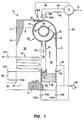
- FIG. 1 is a schematic view partially in section, depicting the fluidized bed reactor of the present invention;
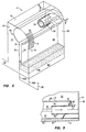
- FIG. 2 is a perspective/schematic view of the fluidized bed reactor of FIG. 1 depicting the horizontal cyclone separator, and
- FIG. 3 is a partial enlarged sectional view of a portion of the reactor taken along line 3-3 of FIG. 2.
- Referring to FIGS. 1 and 2 of the drawings, the
reference numeral 10 refers to a fluidized bed reactor of the present invention forming a portion of a steam generating system including asteam drum 12 which receives water from afeed pipe 14 and is connected to the reactor by fluid flow circuitry, subsequently discussed. - The
reactor 10 is disposed below thesteam drum 12 and includes a vessel defined by afront wall 16, a spaced, parallelrear wall 18 and first and secondintermediate partitions walls second sidewalls 24 and 26 (FIG. 2), extend perpendicular to thefront wall 16 and therear wall 18 to form a substantially rectangular vessel. The upper portions of thewalls wall 16 and thepartition 22, along with corresponding positions of thesidewalls furnace section 28. Thewall 18 and thepartition 20, along with corresponding positions of thesidewalls heat recovery section 30. The upper ends of thewalls partition 20 are slightly spaced relative to each other and bent for connection to the fluid flow circuitry, as will be described. - The
walls partition 20 and thesidewalls - The inner surfaces of the upper, curved portions of the
walls partitions wall 18 and the partitions, are lined with a refractory 32 or other suitable erosion-protection material. Although not shown in the drawings, it is understood that therefractory 32 extends across the spaces between the ends of thewalls partition 20 for substantially enclosing the vessel. - Flow circuitry is provided to pass water, steam and/or a water-steam mixture (hereinafter termed "fluid") through the tubes to heat the fluid to the extent that it can be used to perform work such as, for example, driving a steam turbine (not shown). To this end,
headers wall 16 andheaders partition 20 for introducing fluid to, and receiving fluid from, the tubes forming the respective walls. Adowncomer 38 connects thesteam drum 12 to theheaders branch conduits Conduits 42 and 44 connect theleaders steam drum 12 for returning fluid from the headers to the drum. - Similarly,
headers rear wall 18 for introducing fluid to, and receiving fluid from, the tubes forming the latter wall. Aconduit 48 connects thesteam drum 12 to theheader 46A, for passing fluid to the tubes of thewall 18. Theheader 46B is connected to additional flow circuitry, described below. - A
tube bank 50 is disposed in theheat recovery section 30 for removing heat from the heat recovery section in a manner to be described. Aconduit 52 registers with an opening formed in a lower end portion of thewall 18 for discharging gases from theheat recovery section 30 in a manner to be described.Headers tube bank 50. Aconduit 56 connects theheader 46B of thewall 18 to theheader 54B for passing fluid from the tubes of the wall to thetube bank 50. Fluid exiting thetube bank 50 through theheader 54A is passed to thesteam drum 12 and/or to the steam turbine, or both, through additional flow circuitry (not shown). - Although not shown, flow circuitry similar to that described above is provided for the
sidewalls reactor 10 may be equipped with additional flow circuitry for improving the transfer of heat from thereactor 10. Other heat, reheat and superheat functions, also not shown, are contemplated. Since these techniques are conventional, they will not be discussed further. - A perforated
air distribution plate 58 is suitably supported at a lower portion of thefurnace section 28 and defines aplenum chamber 60. Air from a suitable source (not shown) is introduced into theplenum chamber 60 by conventional means, such as a forced-draft blower 62, or the like. The air introduced through theplenum chamber 60 passes in an upwardly direction to theair distribution plate 58 and may be preheated by air preheaters (not shown) and appropriately regulated by air control dampers (also not shown) as needed. - The
air distribution plate 58 is adapted to support a bed of particulate fuel material consisting, in general, of crushed coal and limestone, or dolomite, for absorbing the sulfur formed during the combustion of the coal. A fuel distributor pipe (schematically represented by line 64 in FIG. 1) extends through thefront wall 16 for introducing particulate fuel into thefurnace section 28, it being understood that other pipes can be associated with the walls defining the furnace section for distributing particulate sorbent material and/or additional particulate fuel material into the furnace section as needed. It is understood that a drain pipe (not shown) registers with an opening in theair distribution place 58 and extends through theplenum 60 for discharging spent fuel and sorbent material from thefurnace section 28 to external equipment. - An air pipe represented by
line 66 in FIG. 1, is connected to theblower 62 and extends through thefront wall 16 at a predetermined elevation from theplate 58 to introduce secondary air into thefurnace section 28, for reasons to be described. It is understood that a plurality of air ports (not shown) at one or more elevations can be provided through thewall 16 and any of the other walls defining thefurnace section 28 for discharging the air from theline 66 into the furnace section. - A horizontal cyclone separator designated generally by the
reference numeral 68 is provided in an upper portion of the vessel formed by thereactor 10. Theseparator 68 includes a horizontally-disposedvortex chamber 70 for separating solid particles from a mixture of gases and particles, in a manner to be described. Thevortex chamber 70 is generally cylindrical and defined by the upper, curved portions of thefront wall 16, thepartition 20 and thepartition 22. The upper edge of thepartition 22 is spaced laterally from thefront wall 16 to define aninlet duct 72 extending the full length of thefurnace section 28. The lower portion of thepartition 22 is adjacent to, and parallel with, thepartition 20 to define anoutlet trough 74 extending from a lower portion of thevortex chamber 70 to an area just above thedistribution plate 58. Thetrough 74 extends the full length of thefurnace section 28 into the fuel bed on theplate 58. - A
central tube 76 extends coaxially within a portion of thevortex chamber 70 for receiving clean gases from the vortex chamber and passing them to theheat recovery section 30, as will be described. Thetube 76 extends from theside wall 26 and is sufficient in length to promote the circular flow of the mixture of gases and the particulate material in thechamber 70, yet also allows for efficient passage of the clean gases into an open end thereof. Ahelical wall 78 extends across the annular space between the surface of thetube 76 and the curved portions of thewall 16 and thepartitions vortex chamber 70. One end of thehelical wall 78 is located at theside wall 26 and the helical wall spirally encircles thecentral tube 76 and terminates at the upper edge of thepartition 22. Thehelical wall 78 forms a helical end of thevortex chamber 70 for supporting thetube 76 and also for directing the mixture received through theinlet duct 72 spirally within the chamber in the direction of the other end thereof, as will be subsequently described. - Referring also to FIG. 3, an
outlet opening 80 is provided in the portion of thetube 76 outside thevortex chamber 70 and behind thehelical wall 78. Theoutlet opening 80 is formed by removing a section of the wall of thetube 76, and opens directly into theheat recovery section 30 for passing the clean gases from thechamber 70 into the heat recovery section, as will be described. - In operation, a particulate material, including coal, is provided on the
air distribution plate 58 and is ignited by a light-off burner (not shown), or the like, while air is introduced into theplenum chamber 60. Additional material is introduced through the distributor 64 into the interior of thefurnace section 28 as needed. As the combustion of the coal progresses, additional air is introduced into theplenum chamber 60 in quantities that comprise a fraction of the total air required for complete combustion so that the combustion in the lower portion of thefurnace section 28 is incomplete. The latter section thus operates under reducing conditions and the remaining air required for complete combustion is supplied by theair pipe 66. The range of air supplied through theplenum chamber 60 can be, for example, from 40%-90% of that required for complete combustion, while the remaining air (10%-60%) is supplied through thepipe 66. - The high-pressure, high-velocity, combustion-supporting air introduced through the
air distribution plate 58 from theplenum chamber 60 is at a velocity which is greater than the free-fall velocity of the relatively fine particles in the bed and less than the free-fall velocity of relatively course particles. Thus, a portion of the fine particles become entrained and pneumatically transported by air and the combustion gases. This mixture of entrained particles and gases rises upwardly within thefurnace section 28 and passes through theinlet duct 72 along the entire length of thefurnace section 28 into thevortex chamber 70 of thecyclone separator 68. Theinlet duct 72 is arranged so that the mixture enters in a direction substantially tangential to thevortex chamber 70 and thus swirls around in the chamber. The entrained solid particles are thus propelled by centrifugal forces against the inner surfaces of thewall 16 and thepartitions vortex chamber 70, where they collect and fall downwardly by gravity into thetrough 74. Thepartition 22 extends sufficiently into the fuel bed supported by thedistribution plate 58 so that the particles can flow from thetrough 74 into the bed as needed for recycle, while sealing against backflow of the high-pressure gases from thefurnace section 28. - The mixture circulating in the
vortex chamber 70 is directed by thehelical wall 78 to flow in a spiral fashion toward one end of the chamber, i.e., in a direction towards thewall 24. The pressure changes created by the spiral flow force the relatively clean gases concentrating along the central axis of thechamber 70 toward the low pressure area created at the opening of thetube 76. The clean gases thus pass into thetube 76 and exit through the outlet opening 80 directly into theheat recovery section 30. Since thetube 76 rests against thesidewall 26, the gases leave through the outlet opening 80 generally perpendicular to the axis of thetube 76, which is also generally parallel to the direction of entry of the mixture into theseparator 68 through theinlet duct 72. - Water is introduced into the
steam drum 12 through thewater feed pipe 14 and is conducted downwardly through thedowncomer 38 into thelower headers wall 16 andpartition 20, as described above. Heat from the fluidized bed, the gas column, and the transported solids converts a portion of the water into steam, and the mixture of water and steam rises in the tubes, collects in theupper headers steam drum 12 through theconduits 42, 44. The steam and water are separated within thesteam drum 12 in a conventional manner, and the separated steam is conducted from the steam drum through theconduit 48 and theheader 40A to the tubes forming thewall 18 of theheat recovery section 30. The steam is then passed from thelower header 46B by theconduit 56 to theheader 54B and into thetube bank 50 for absorbing additional heat from the gases passing through theheat recovery section 30. The steam is thereafter passed through additional flow circuitry to the drum and/or to a steam turbine, or the like (not shown). The separated fluid is mixed with the fresh supply of water from thefeed pipe 14 and is recirculated through the flow circuitry in the manner just described. Other cooling surfaces, preferably in the form of partition walls with essentially vertical tubes, can be utilized in thefurnace section 28. For example, while not shown, thepartition 22 may be provided with vertical tubes and connected to the flow circuitry. - The hot clean gases from the
separator 68 enter theheat recovery section 30 through theoutlet opening 80 and pass over thetube bank 50 to remove additional heat from the gases and add heat to the steam or water flowing through the latter tubes. The gases are then directed to theoutlet conduit 52 and exit from theheat recovery section 30. If the air which is introduced into theplenum 60 is at a relatively high pressure on the order of 10 atmospheres, the gases from theoutlet conduit 52 may be directed to a gas turbine, or the like (not shown). - It is thus seen that the reactor of the present invention provides several advantages. For example, the provision of the horizontal cyclone separator integrated in the upper portion of the vessel of the
reactor 10, with thereturn trough 74 connected directly to the fuel bed of thefurnace section 28, permits the separation of the entrained particles and the recycling of same back to the furnace section while eliminating the need for relatively bulky and expensive vertical cyclone separators. Thus, thereactor 10 of the present invention is relatively compact and can be fabricated into modules for easy transportation and fast erection which is especially advantageous when the reactor is used as a steam generator, as disclosed. Also the mixture enters thevortex chamber 70 generally tangentially through theinlet opening 68 extending along the entire length of the furnace section, without being significantly redirected by unnecessary baffles, tubes and/or ducting, and thevortex chamber 70 is configured for improved circulation and separation of the solid particles from the gases of the mixture generated in thefurnace section 28. - Further, the
central tube 76 promotes well-defined circulation in thechamber 70. The spiral circulation of the mixture caused by thehelical wall 78 also improves the transfer of the clean gases into the opening of thetube 76 and thus into theheat recovery section 30. Additionally, since thetube 76 is confined within the vessel of thereactor 10 and theoutlet opening 80 is provided just behind the end of thechamber 70 formed by thehelical wall 78, the hot, clean gases are transferred directly and quickly into the heat recovery section without the need for additional piping and intricate duct arrangements. - Further, the temperature of the
separator 68 is reduced considerably due to the relatively cool fluid passing through its walls to reduce heat losses from the separator and minimize the requirement for internal refractory insulation. The need for extended and expensive high temperature refractory-lined duct work and expansion joints between the reactor and cyclone separator, and between the latter and the heat recovery section is also minimized. - It is understood that variations in the foregoing can be made within the scope of the invention. For example, the walls of the vessel of the
reactor 10 may be reconfigured to accommodate more than one horizontal cyclone separator in the upper portion thereof in communication with the furnace section. Also, while the headers and flow circuitry have been described and shown in the drawings, it should be understood that any other suitable header and flow circuitry arrangement could be employed in connection with the present invention.
Claims (14)
- A cyclone separator comprising curved walls to define a generally cylindrical vortex chamber for separating particles from a mixture of gases and said particles by centrifugal forces, an inlet means defined by said walls along the length of said chamber for receiving said mixture into said chamber, an outlet means defined by said walls along the length of said chamber for removing said separated particles from said chamber and a tube coaxially disposed within a portion of said chamber for discharging said gases therefrom.
- A separator as claimed in Claim 1, further comprising a helical wall forming an end of said chamber in the annular space between said tube and said curved walls for circulating said mixture spirally within said chamber.
- The separator as claimed in Claim 1 or Claim 2 in which the vortex chamber is horizontally disposed.
- A separator as claimed in any preceding claim further comprising a plurality of tubes extending in a parallel relationship for at least a portion of their lengths over at least a portion of said curved walls, headers connected to the ends of said tubes, and means for circulating a cooling fluid through said headers and said tubes to cool said curved walls.
- A separator as claimed in any preceding claim in which at least a portion of the curved walls include a refractory material.
- A separator as claimed in any preceding claim in which the inlet means is defined by laterally spaced, longitudinal portions of the curved walls.
- A separator as claimed in any preceding claim in which the outlet means is a trough defined by lower, parallel portions of the walls.
- A separator as claimed in any preceding claim in which the tube extends less than approximately one half the length of the chamber from the said end.
- A separator as claimed in any preceding claim in which the tube is linear and includes an opening in a side portion thereof outside the chamber.
- A separator as claimed in Claim 9 in which the gases are discharged through the said opening generally perpendicular to the central axis of the tube.
- A fluidized bed reactor comprising walls to define a vessel, a plurality of generally parallel tubes forming at least a portion of said vessel walls, header means connected to the ends of said tubes, means for circulating a heat transfer fluid through said header means and said tubes for the transfer of heat from said vessel, a furnace section and a heat recovery section defined at least in part by said vessel, said furnace section including a fuel bed in a lower portion thereof, means for combusting said fuel to generate heat and a mixture of particulate material and gases, and at least one cyclone separator disposed within the upper portion of said vessel for receiving said mixture and discharging said gases to said heat recovery section and returning said material to said bed, said separator including walls comprised at least in part by said vessel walls to define a generally cylindrical vortex chamber for separating said material from said gases by centrifugal forces, an inlet means defined by said separator walls along the length of said chamber for receiving said mixture, a trough defined by said separator walls along the length of the bottom of said chamber and forming a partition between said heat recovery and said furnace sections for discharging said separated material directly into said bed, and a tube coaxially disposed within a portion of said chamber for transferring said gases directly to said heat recovery section.
- A reactor as claimed in Claim 11 comprising a helical wall forming an end of the chamber in the annular space between the tube and the separator walls for circulating the mixture spirally within the chamber.
- A fluidized bed reactor as claimed in Claim 11 or Claim 12 in which the tube terminates within the vessel and opens in a side portion thereof directly into the heat recovery section in the region of the tube behind the helical wall.
- A fluidized bed reactor as claimed in any of Claims 11 to 13 in which the vortex chamber is horizontally disposed.
Priority Applications (4)
| Application Number | Priority Date | Filing Date | Title |
|---|---|---|---|
| US07/505,806 US5174799A (en) | 1990-04-06 | 1990-04-06 | Horizontal cyclone separator for a fluidized bed reactor |
| CA002080319A CA2080319A1 (en) | 1990-04-06 | 1992-10-09 | Horizontal cyclone separator for a fluidized bed reactor |
| EP92309357A EP0592737A1 (en) | 1990-04-06 | 1992-10-14 | Horizontal cyclone separator for a fluidized bed reactor |
| JP4283242A JPH0798163B2 (en) | 1990-04-06 | 1992-10-21 | Horizontal cyclone separator for fluidized bed reactor |
Applications Claiming Priority (4)
| Application Number | Priority Date | Filing Date | Title |
|---|---|---|---|
| US07/505,806 US5174799A (en) | 1990-04-06 | 1990-04-06 | Horizontal cyclone separator for a fluidized bed reactor |
| CA002080319A CA2080319A1 (en) | 1990-04-06 | 1992-10-09 | Horizontal cyclone separator for a fluidized bed reactor |
| EP92309357A EP0592737A1 (en) | 1990-04-06 | 1992-10-14 | Horizontal cyclone separator for a fluidized bed reactor |
| JP4283242A JPH0798163B2 (en) | 1990-04-06 | 1992-10-21 | Horizontal cyclone separator for fluidized bed reactor |
Publications (1)
| Publication Number | Publication Date |
|---|---|
| EP0592737A1 true EP0592737A1 (en) | 1994-04-20 |
Family
ID=27426965
Family Applications (1)
| Application Number | Title | Priority Date | Filing Date |
|---|---|---|---|
| EP92309357A Withdrawn EP0592737A1 (en) | 1990-04-06 | 1992-10-14 | Horizontal cyclone separator for a fluidized bed reactor |
Country Status (4)
| Country | Link |
|---|---|
| US (1) | US5174799A (en) |
| EP (1) | EP0592737A1 (en) |
| JP (1) | JPH0798163B2 (en) |
| CA (1) | CA2080319A1 (en) |
Cited By (3)
| Publication number | Priority date | Publication date | Assignee | Title |
|---|---|---|---|---|
| EP0700728A1 (en) * | 1994-08-11 | 1996-03-13 | Foster Wheeler Energy Corporation | Horizontal cyclone separator for a fluidized bed reactor |
| WO1997029324A1 (en) * | 1996-02-08 | 1997-08-14 | Abb Patent Gmbh | Device for separating solids particles from the gas flow of a fluid bed |
| EP3147481A1 (en) * | 2015-09-22 | 2017-03-29 | United Technologies Corporation | Apparatus and method for air particle separation in a gas turbine engine |
Families Citing this family (18)
| Publication number | Priority date | Publication date | Assignee | Title |
|---|---|---|---|---|
| US5174799A (en) * | 1990-04-06 | 1992-12-29 | Foster Wheeler Energy Corporation | Horizontal cyclone separator for a fluidized bed reactor |
| US5325823A (en) * | 1992-12-24 | 1994-07-05 | Foster Wheeler Energy Corporation | Large scale fluidized bed reactor |
| US5394937A (en) * | 1993-03-05 | 1995-03-07 | Nieh; Sen | Vortex heat exchange method and device |
| DE19841586A1 (en) * | 1998-09-11 | 2000-03-16 | Metallgesellschaft Ag | Stationary bed fuel gasification reactor, for gasification of coal, comprises centrifugal separator for solids removal from the product gas |
| US7537622B2 (en) * | 2001-10-10 | 2009-05-26 | Fmi Newcoal, Inc. | Process for drying coal |
| US8197561B2 (en) | 2001-10-10 | 2012-06-12 | River Basin Energy, Inc. | Process for drying coal |
| US7695535B2 (en) | 2001-10-10 | 2010-04-13 | River Basin Energy, Inc. | Process for in-situ passivation of partially-dried coal |
| CN1319621C (en) * | 2005-06-20 | 2007-06-06 | 中国石油大学(北京) | Gas-solid separator with central exhaust pipe |
| US20080271335A1 (en) * | 2007-05-03 | 2008-11-06 | Archer-Daniele-Midland Company | System for using heat to process an agricultural product, a fluidized bed combustor system, and methods of employing the same |
| US8956426B2 (en) | 2010-04-20 | 2015-02-17 | River Basin Energy, Inc. | Method of drying biomass |
| US9057037B2 (en) | 2010-04-20 | 2015-06-16 | River Basin Energy, Inc. | Post torrefaction biomass pelletization |
| CN102980177B (en) * | 2012-11-29 | 2015-11-18 | 湘潭锅炉有限责任公司 | A kind of biological material-burning fluidized bed boiler |
| CN104633631A (en) * | 2013-11-14 | 2015-05-20 | 酒泉市汉鑫科技有限公司 | Biomass boiler |
| CN104841229B (en) * | 2015-05-19 | 2017-01-11 | 青岛科技大学 | Combined dust removal device |
| CN108463151B (en) | 2015-11-10 | 2021-07-23 | 创科实业有限公司 | Hand-held vacuum cleaner |
| CA3062449A1 (en) * | 2017-05-01 | 2018-11-08 | Universite Catholique De Louvain | Device for treating particles in a rotating fluidized bed |
| CN107940449A (en) * | 2017-12-20 | 2018-04-20 | 眉山市鸿宇纸业有限公司 | A kind of boiler smoke folded angle separator |
| US11697100B2 (en) | 2018-07-02 | 2023-07-11 | Metso Outotec Finland Oy | Device and method for cooling or heating a fine-grained solid |
Citations (6)
| Publication number | Priority date | Publication date | Assignee | Title |
|---|---|---|---|---|
| DE392534C (en) * | 1923-01-19 | 1924-03-27 | Hartmann Akt Ges Maschf | Centrifugal wet separator |
| WO1985004117A1 (en) * | 1984-03-20 | 1985-09-26 | Rauma-Repola Oy | Two- or multi-component reactor |
| FR2564747A1 (en) * | 1984-05-25 | 1985-11-29 | Ahlstroem Oy | METHOD AND MEANS FOR CONTROLLING THE OPERATION OF A RECYCLED FLUIDIZED BED REACTOR |
| WO1986004402A1 (en) * | 1985-01-29 | 1986-07-31 | A. Ahlstrom Corporation | Circulating fluidizied bed boiler |
| WO1987001791A1 (en) * | 1985-09-11 | 1987-03-26 | A. Ahlstrom Corporation | Circulating fluidized bed reactor |
| US5174799A (en) * | 1990-04-06 | 1992-12-29 | Foster Wheeler Energy Corporation | Horizontal cyclone separator for a fluidized bed reactor |
Family Cites Families (15)
| Publication number | Priority date | Publication date | Assignee | Title |
|---|---|---|---|---|
| US474490A (en) * | 1892-05-10 | Dust-collector | ||
| US928673A (en) * | 1908-07-20 | 1909-07-20 | Sturtevant Eng Co Ltd | Centrifugal apparatus for separating solid matters from air. |
| US2339416A (en) * | 1941-02-14 | 1944-01-18 | B F Sturtevant Co | Dust concentrator |
| GB587240A (en) * | 1943-07-02 | 1947-04-18 | L Von Roll Ag Fuer Kommunale A | Improvements in steam-boiler plant provided with soot, ashes, dust and like separators of the cyclone type |
| US2973094A (en) * | 1958-09-02 | 1961-02-28 | Claude B Schneible Co | Separating apparatus and method |
| JPS5153576U (en) * | 1974-10-21 | 1976-04-23 | ||
| DE2832097C2 (en) * | 1978-07-21 | 1983-12-22 | Messerschmitt-Bölkow-Blohm GmbH, 8000 München | Process and device for separating materials by means of centrifugal force |
| FI842202A0 (en) * | 1984-06-01 | 1984-06-01 | Ahlstroem Oy | ANCILLATION OF THE FAST MATERIAL I REACTOR WITH CIRCULAR BEDD. |
| FI70528C (en) * | 1984-06-01 | 1987-11-25 | Ahlstroem Oy | Apparatus for separating solids in circulating bed reactor. |
| FI85414C (en) * | 1985-01-29 | 1992-04-10 | Ahlstroem Oy | ANORDINATION FOR AVAILABILITY OF FAST MATERIAL ON A FREON AND REACTOR WITH A CIRCULAR BEDD. |
| US4713098A (en) * | 1986-01-31 | 1987-12-15 | Foster Wheeler Energy Corporation | Tandem curved arm steam-water separator |
| US4731228A (en) * | 1986-06-16 | 1988-03-15 | Shell Oil Company | Reactor and horizontal cyclone separator with primary mass flow and secondary centrifugal separation of solid and fluid phases |
| US4732113A (en) * | 1987-03-09 | 1988-03-22 | A. Ahlstrom Corporation | Particle separator |
| US4746337A (en) * | 1987-07-06 | 1988-05-24 | Foster Wheeler Energy Corporation | Cyclone separator having water-steam cooled walls |
| JPH0250363A (en) * | 1988-08-11 | 1990-02-20 | Matsushita Electric Ind Co Ltd | Digital signal processor |
-
1990
- 1990-04-06 US US07/505,806 patent/US5174799A/en not_active Expired - Fee Related
-
1992
- 1992-10-09 CA CA002080319A patent/CA2080319A1/en not_active Abandoned
- 1992-10-14 EP EP92309357A patent/EP0592737A1/en not_active Withdrawn
- 1992-10-21 JP JP4283242A patent/JPH0798163B2/en not_active Expired - Lifetime
Patent Citations (6)
| Publication number | Priority date | Publication date | Assignee | Title |
|---|---|---|---|---|
| DE392534C (en) * | 1923-01-19 | 1924-03-27 | Hartmann Akt Ges Maschf | Centrifugal wet separator |
| WO1985004117A1 (en) * | 1984-03-20 | 1985-09-26 | Rauma-Repola Oy | Two- or multi-component reactor |
| FR2564747A1 (en) * | 1984-05-25 | 1985-11-29 | Ahlstroem Oy | METHOD AND MEANS FOR CONTROLLING THE OPERATION OF A RECYCLED FLUIDIZED BED REACTOR |
| WO1986004402A1 (en) * | 1985-01-29 | 1986-07-31 | A. Ahlstrom Corporation | Circulating fluidizied bed boiler |
| WO1987001791A1 (en) * | 1985-09-11 | 1987-03-26 | A. Ahlstrom Corporation | Circulating fluidized bed reactor |
| US5174799A (en) * | 1990-04-06 | 1992-12-29 | Foster Wheeler Energy Corporation | Horizontal cyclone separator for a fluidized bed reactor |
Cited By (4)
| Publication number | Priority date | Publication date | Assignee | Title |
|---|---|---|---|---|
| EP0700728A1 (en) * | 1994-08-11 | 1996-03-13 | Foster Wheeler Energy Corporation | Horizontal cyclone separator for a fluidized bed reactor |
| WO1997029324A1 (en) * | 1996-02-08 | 1997-08-14 | Abb Patent Gmbh | Device for separating solids particles from the gas flow of a fluid bed |
| EP3147481A1 (en) * | 2015-09-22 | 2017-03-29 | United Technologies Corporation | Apparatus and method for air particle separation in a gas turbine engine |
| US10202903B2 (en) | 2015-09-22 | 2019-02-12 | United Technologies Corporation | Apparatus and method for air particle separation in a gas turbine engine |
Also Published As
| Publication number | Publication date |
|---|---|
| JPH06134346A (en) | 1994-05-17 |
| US5174799A (en) | 1992-12-29 |
| CA2080319A1 (en) | 1994-04-10 |
| JPH0798163B2 (en) | 1995-10-25 |
Similar Documents
| Publication | Publication Date | Title |
|---|---|---|
| US5174799A (en) | Horizontal cyclone separator for a fluidized bed reactor | |
| CA1318196C (en) | Fluidized bed steam generation system and method having an external heat exchanger | |
| JP2631919B2 (en) | Fluidized bed combustion apparatus and operation method thereof | |
| EP0365723A1 (en) | Fluidized bed reactor having an integrated recycle heat exchanger | |
| JP2657863B2 (en) | Fluid bed combustion apparatus and method with recirculating heat exchanger with non-mechanical solids control | |
| US4951612A (en) | Circulating fluidized bed reactor utilizing integral curved arm separators | |
| EP0346062B1 (en) | A fluidized bed reactor utilizing channel separators | |
| EP0633429B1 (en) | Fluidized bed steam generation system and method of using recycled flue gases to assist in passing loopseal solids | |
| US4745884A (en) | Fluidized bed steam generating system | |
| EP0587351A1 (en) | Fluidized bed reactor system and method of operating same | |
| JP2551529B2 (en) | Large scale fluidized bed reactor | |
| US5218931A (en) | Fluidized bed steam reactor including two horizontal cyclone separators and an integral recycle heat exchanger | |
| EP0700728B1 (en) | Fluidized bed reactor | |
| US5277151A (en) | Integral water-cooled circulating fluidized bed boiler system | |
| US4955190A (en) | Method for driving a gas turbine utilizing a hexagonal pressurized fluidized bed reactor | |
| US5253741A (en) | Fluidized bed steam reactor including two horizontal cyclone separators and an integral recycle heat exchanger | |
| EP0595487A1 (en) | Fluidized bed reactor including a stripper-cooler and method of operating same | |
| EP0413612B1 (en) | Fluidized bed steam generating system including a steam cooled cyclone separator | |
| EP0398718B1 (en) | Solids recycle seal system for a fluidized bed reactor |
Legal Events
| Date | Code | Title | Description |
|---|---|---|---|
| PUAI | Public reference made under article 153(3) epc to a published international application that has entered the european phase |
Free format text: ORIGINAL CODE: 0009012 |
|
| AK | Designated contracting states |
Kind code of ref document: A1 Designated state(s): ES GB IT PT |
|
| 17P | Request for examination filed |
Effective date: 19941005 |
|
| STAA | Information on the status of an ep patent application or granted ep patent |
Free format text: STATUS: THE APPLICATION HAS BEEN WITHDRAWN |
|
| 18W | Application withdrawn |
Withdrawal date: 19960325 |