EP0592326A1 - Trenching apparatus for digging deep trenches with cutting drums - Google Patents
Trenching apparatus for digging deep trenches with cutting drums Download PDFInfo
- Publication number
- EP0592326A1 EP0592326A1 EP93402485A EP93402485A EP0592326A1 EP 0592326 A1 EP0592326 A1 EP 0592326A1 EP 93402485 A EP93402485 A EP 93402485A EP 93402485 A EP93402485 A EP 93402485A EP 0592326 A1 EP0592326 A1 EP 0592326A1
- Authority
- EP
- European Patent Office
- Prior art keywords
- platform
- lifting mast
- chassis
- mast
- reels
- Prior art date
- Legal status (The legal status is an assumption and is not a legal conclusion. Google has not performed a legal analysis and makes no representation as to the accuracy of the status listed.)
- Granted
Links
Images

Classifications
-
- E—FIXED CONSTRUCTIONS
- E02—HYDRAULIC ENGINEERING; FOUNDATIONS; SOIL SHIFTING
- E02F—DREDGING; SOIL-SHIFTING
- E02F9/00—Component parts of dredgers or soil-shifting machines, not restricted to one of the kinds covered by groups E02F3/00 - E02F7/00
-
- E—FIXED CONSTRUCTIONS
- E02—HYDRAULIC ENGINEERING; FOUNDATIONS; SOIL SHIFTING
- E02F—DREDGING; SOIL-SHIFTING
- E02F3/00—Dredgers; Soil-shifting machines
- E02F3/04—Dredgers; Soil-shifting machines mechanically-driven
- E02F3/18—Dredgers; Soil-shifting machines mechanically-driven with digging wheels turning round an axis, e.g. bucket-type wheels
- E02F3/20—Dredgers; Soil-shifting machines mechanically-driven with digging wheels turning round an axis, e.g. bucket-type wheels with tools that only loosen the material, i.e. mill-type wheels
- E02F3/205—Dredgers; Soil-shifting machines mechanically-driven with digging wheels turning round an axis, e.g. bucket-type wheels with tools that only loosen the material, i.e. mill-type wheels with a pair of digging wheels, e.g. slotting machines
-
- E—FIXED CONSTRUCTIONS
- E02—HYDRAULIC ENGINEERING; FOUNDATIONS; SOIL SHIFTING
- E02F—DREDGING; SOIL-SHIFTING
- E02F3/00—Dredgers; Soil-shifting machines
- E02F3/04—Dredgers; Soil-shifting machines mechanically-driven
- E02F3/18—Dredgers; Soil-shifting machines mechanically-driven with digging wheels turning round an axis, e.g. bucket-type wheels
- E02F3/22—Component parts
- E02F3/24—Digging wheels; Digging elements of wheels; Drives for wheels
- E02F3/246—Digging wheels; Digging elements of wheels; Drives for wheels drives
-
- E—FIXED CONSTRUCTIONS
- E02—HYDRAULIC ENGINEERING; FOUNDATIONS; SOIL SHIFTING
- E02F—DREDGING; SOIL-SHIFTING
- E02F9/00—Component parts of dredgers or soil-shifting machines, not restricted to one of the kinds covered by groups E02F3/00 - E02F7/00
- E02F9/08—Superstructures; Supports for superstructures
- E02F9/0808—Improving mounting or assembling, e.g. frame elements, disposition of all the components on the superstructures
Landscapes
- Engineering & Computer Science (AREA)
- Mining & Mineral Resources (AREA)
- Civil Engineering (AREA)
- General Engineering & Computer Science (AREA)
- Structural Engineering (AREA)
- Mechanical Engineering (AREA)
- Earth Drilling (AREA)
- Pit Excavations, Shoring, Fill Or Stabilisation Of Slopes (AREA)
Abstract
Description
La présente invention est relative à un appareil pour creuser dans le sol des tranchées de grande profondeur à l'aide de tambours de fraisage.The present invention relates to an apparatus for digging deep trenches in the ground using milling drums.
On connaît déjà de tels appareils dans lesquels un châssis supporté par des câbles est muni à sa partie inférieure de deux tambours de fraisage à axes parallèles qui tournent en directions opposées pour désagréger le terrain et creuser la tranchée, tandis que le châssis s'enfonce dans le sol.We already know of such devices in which a chassis supported by cables is provided at its lower part with two milling drums with parallel axes which rotate in opposite directions to disintegrate the ground and dig the trench, while the chassis sinks into floor.
Ces appareils comportent une conduite flexible de section relativement importante qui s'étend depuis le voisinage des tambours de fraisage jusqu'à la surface du sol pour permettre le refoulement du mélange constitué par la boue initialement présente dans la tranchée et les matériaux résultant de la désagrégation du sol par les tambours de fraisage. Diverses autres canalisations hydrauliques ou électriques permettent notamment de fournir l'énergie nécessaire à l'entraînement des tambours de fraisage.These devices include a flexible pipe of relatively large section which extends from the vicinity of the milling drums to the ground surface to allow the discharge of the mixture constituted by the mud initially present in the trench and the materials resulting from the disintegration. from the ground by the milling drums. Various other hydraulic or electrical lines make it possible in particular to supply the energy necessary for driving the milling drums.
Les appareils de ce type peuvent creuser des tranchées dont la profondeur est généralement de l'ordre de quelques dizaines de mètres.Devices of this type can dig trenches, the depth of which is generally of the order of a few tens of meters.
Ces appareils présentent généralement des dimensions importantes qui rendent leur transport difficile, en particulier du fait que leur démontage est presque toujours indispensable.These devices generally have large dimensions which make their transport difficult, in particular because their disassembly is almost always essential.
La présente invention a pour but de réaliser un appareil du type décrit ci-dessus qui, tout en conservant ou en améliorant les performances des appareils de type connu, présente un faible encombrement qui lui permet d'être transporté facilement, par exemple sur route, du fait que son gabarit demeure inférieur aux limites fixées par la réglementation en vigueur pour des déplacements courants sur les routes.The object of the present invention is to produce a device of the type described above which, while retaining or improving the performance of devices of known type, has a small footprint which allows it to be transported easily, for example on the road, the fact that its size remains below the limits set by the regulations in force for current travel on the roads.
L'appareil selon l'invention présente également l'avantage de constituer un ensemble complet qui comporte la totalité des éléments nécessaires à son fonctionnement, c'est-à-dire un groupe fournissant l'énergie, un mât de levage articulé qui supporte le châssis et les tambours de fraisage, des enrouleurs qui supportent des canalisations de différentes natures, ainsi qu'un poste de commande.The apparatus according to the invention also has the advantage of constituting a complete assembly which includes all the elements necessary for its operation, that is to say a group supplying the energy, an articulated lifting mast which supports the chassis and milling drums, reels which support pipes of different natures, as well as a control station.
L'appareil selon l'invention est disposé sur une plate-forme, avantageusement munie de chenilles.The apparatus according to the invention is arranged on a platform, advantageously provided with tracks.
La présente invention a pour objet un appareil pour creuser dans le sol des tranchées de grande profondeur à l'aide de tambours de fraisage, caractérisé par le fait qu'il comporte en combinaison : une plate-forme supportée par un train de roulement tel que des chenilles ; un mât de levage articulé sur la plate-forme au voisinage de l'une des extrémités de cette dernière et maintenu en position de travail, de préférence à l'aide d'au moins un vérin disposé au voisinage de l'autre extrémité de la plate-forme ; un châssis suspendu à l'extrémité haute du mât de levage par l'intermédiaire de câbles ; des tambours de fraisage, entraînables en rotation, montés à la partie inférieure du châssis ; un enrouleur à axe horizontal situé sur la plate-forme à côté du mât de levage, supportant une conduite flexible pour remonter les déblais depuis le voisinage des tambours de fraisage jusqu'à la surface du sol, le plan médian dudit enrouleur coupant le plan médian du mât de levage sensiblement selon l'axe vertical du châssis ; au moins un groupe d'enrouleurs à axe horizontal situé sur la plate-forme en-dessous du mât de levage, supportant des canalisations flexibles qui aboutissent au châssis pour alimenter ce dernier en énergie, et pour assurer le positionnement des tambours de fraisage ; un poste de commande de l'appareil, situé sur la plate-forme à côté du mât de levage et devant l'enrouleur de la conduite de remontage des déblais ; et un groupe fournissant l'énergie nécessaire au fonctionnement de l'appareil, situé à l'extrémité de la plate-forme qui est opposée au châssis supportant les tambours de fraisage.The present invention relates to an apparatus for digging deep trenches in the ground using milling drums, characterized in that it comprises in combination: a platform supported by a running gear such as caterpillars; a lifting mast articulated on the platform in the vicinity of one of the ends of the latter and maintained in the working position, preferably by means of at least one jack arranged in the vicinity of the other end of the platform; a chassis suspended from the upper end of the lifting mast by cables; milling drums, rotatable, mounted at the bottom of the chassis; a reel with horizontal axis located on the platform next to the lifting mast, supporting a flexible pipe for raising the cuttings from the vicinity of the milling drums to the ground surface, the median plane of said reel cutting the median plane of the lifting mast substantially along the vertical axis of the chassis; at least one group of reels with horizontal axis located on the platform below the lifting mast, supporting flexible pipes which terminate in the chassis to supply the latter with energy, and to ensure the positioning of the milling drums; an appliance control station, located on the platform next to the lifting mast and in front of the reel for the cuttings winding line; and a group supplying the energy necessary for the operation of the apparatus, situated at the end of the platform which is opposite to the chassis supporting the milling drums.
Selon un mode de réalisation particulier de l'invention, la rotation des tambours de fraisage est assurée par des moteurs hydrauliques qui sont alimentés par des canalisations supportées par les enrouleurs disposés en-dessous du mât de levage.According to a particular embodiment of the invention, the rotation of the milling drums is ensured by hydraulic motors which are supplied by pipes supported by the reels arranged below the lifting mast.
De même, dans ce mode de réalisation, le positionnement vertical du châssis dans la tranchée est réalisé à l'aide de vérins hydrauliques qui sont également alimentés par des canalisations supportées par les enrouleurs qui sont placés en-dessous du mât de levage.Likewise, in this embodiment, the vertical positioning of the chassis in the trench is carried out using hydraulic jacks which are also supplied by pipes supported by the reels which are placed below the lifting mast.
Dans un autre mode de réalisation, l'entraînement des tambours de fraisage et la manoeuvre des organes assurant le positionnement du châssis dans la tranchée sont réalisés au moins partiellement à l'aide de moteurs électriques alimentés par des câbles qui sont supportés par les enrouleurs situés en-dessous du mât de levage.In another embodiment, the drive of the milling drums and the operation of the members ensuring the positioning of the chassis in the trench are carried out at least partially using electric motors powered by cables which are supported by the reels located below the lifting mast.
Dans un mode de réalisation préféré de l'invention, les enrouleurs des canalisations qui fournissent notamment l'énergie au châssis sont disposés par groupe côte à côte sur un même axe en étant solidaires en rotation.In a preferred embodiment of the invention, the reels of the pipes which in particular supply energy to the chassis are arranged in groups side by side on the same axis while being integral in rotation.
Pour limiter l'encombrement de ces enrouleurs, et pour éviter que leur largeur dépasse par trop celle du mât, il est avantageux, conformément à un mode de réalisation préféré de l'invention, de limiter le nombre de canalisations qui sont enroulées côte à côte sur un même axe et de disposer deux groupes d'enrouleurs l'un derrière l'autre en-dessous du mât de levage.To limit the size of these reels, and to avoid their width exceeding too much that of the mast, it is advantageous, in accordance with a preferred embodiment of the invention, to limit the number of pipes which are wound side by side on the same axis and to have two groups of reels one behind the other below the lifting mast.
Selon un mode de réalisation préféré de l'invention, tant les enrouleurs des canalisations véhiculant l'énergie que celui supportant la conduite de remontage des déblais, sont entraînés en rotation par des moteurs à couple constant, de manière à permettre un enroulement et un déroulement automatiques des canalisations et de la conduite qui restent ainsi soumises à une tension constante, indépendamment du soulèvement ou de l'abaissement du châssis et des tambours de fraisage.According to a preferred embodiment of the invention, both the reels of the energy-carrying pipes and the one supporting the cuttings winding line, are driven in rotation by motors with constant torque, so as to allow winding and unwinding. automatic lines and pipes which remain subject to constant tension, regardless of the raising or lowering of the chassis and milling drums.
Dans un mode de réalisation préféré de l'invention, le mât de levage peut être déplacé selon sa direction axiale par rapport à la plate-forme de manière à pouvoir augmenter ou diminuer ainsi son porte-à-faux vers l'avant de l'appareil.In a preferred embodiment of the invention, the lifting mast can be moved in its axial direction relative to the platform so as to be able to thereby increase or decrease its overhang towards the front of the apparatus.
Cette caractéristique permet de réduire la longueur hors-tout de l'appareil selon l'invention pour son déplacement, tout en pouvant amener avec précision le châssis à la verticale d'une tranchée que l'on désire réaliser sans avoir à utiliser le train de roulement.This characteristic makes it possible to reduce the overall length of the apparatus according to the invention for its movement, while being able to bring the chassis with precision to the vertical of a trench which it is desired to achieve without having to use the undercarriage. rolling.
Dans un mode de réalisation préféré, l'appareil selon l'invention comporte, au moins à chacun des quatre coins de sa plate-forme, un vérin muni d'une plaque d'appui qui permet de stabiliser l'appareil pendant son fonctionnement et de le soulever pour le maintenir en appui sur le sol sans qu'il repose sur son train de roulement.In a preferred embodiment, the device according to the invention comprises, at least at each of the four corners of its platform, a jack provided with a support plate which makes it possible to stabilize the device during its operation and lift it to keep it resting on the ground without it resting on its undercarriage.
Grâce à cette caractéristique, on peut facilement changer l'orientation du train de roulement en le faisant pivoter alors qu'il ne repose plus sur le sol. On peut également faire reposer l'appareil sur ses plaques d'appui pour démonter ou réparer le train de roulement dont il est équipé.Thanks to this feature, one can easily change the orientation of the undercarriage by rotating it while it is no longer resting on the ground. You can also rest the device on its support plates to dismantle or repair the undercarriage with which it is equipped.
Dans le but de mieux faire comprendre l'invention, on va en décrire maintenant un mode de réalisation donné à titre d'exemple et ne présentant aucun caractère limitatif en référence au dessin annexé dans lequel :
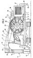
- la figure 1 est une vue en perspective d'un appareil selon un mode de réalisation préféré de l'invention,
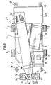
- la figure 2 est une vue en élévation d'une variante de l'appareil représenté sur la figure 1, et
- la figure 3 est une vue de dessus de l'appareil selon l'invention.
- FIG. 1 is a perspective view of an apparatus according to a preferred embodiment of the invention,
- FIG. 2 is an elevation view of a variant of the apparatus shown in FIG. 1, and
- Figure 3 is a top view of the apparatus according to the invention.
Comme on peut le voir sur le dessin, l'appareil selon l'invention, comporte une plate-forme 1 qui repose sur un train de roulement constitué dans le cas présent par des chenilles 2 autour desquelles la plate-forme peut pivoter.As can be seen in the drawing, the device according to the invention comprises a platform 1 which rests on a running gear constituted in this case by
Selon l'invention, un mât de levage 3 repose sur la plate-forme 1 en étant articulé à son extrémité inférieure 4 autour d'un axe horizontal 5 solidaire de l'arrière de la plate-forme 1 et en étant supporté à son extrémité supérieure 6 par un vérin hydraulique 7 monté à l'avant de la plate-forme 1.According to the invention, a
On voit qu'en manoeuvrant le vérin hydraulique 7, on peut élever ou abaisser le mât de levage 3 qui bascule ainsi autour de son axe d'articulation 5.It can be seen that by operating the
Dans le mode de réalisation décrit, l'ensemble constitué par le mât 3, l'axe horizontal 5 et le vérin hydraulique 7 est monté coulissant sur la plate-forme 1, de manière à pouvoir être déplacé vers l'avant de l'appareil dans la direction axiale du mât 3.In the embodiment described, the assembly consisting of the
A cet effet, l'une des extrémités d'un deuxième vérin hydraulique 8 est solidaire en 9 de la plate-forme 1, tandis que son autre extrémité est solidaire de la partie inférieure du mât.For this purpose, one of the ends of a second
Ainsi, en actionnant le vérin 8, on déplace le mât 3 vers l'avant ou vers l'arrière de l'appareil, ce qui permet d'augmenter ou de diminuer le porte-à-faux du mât par rapport à l'avant de la plate-forme.Thus, by actuating the
En particulier, il est avantageux de réduire au minimum ce porte-à-faux pour transporter l'appareil selon l'invention, tandis qu'il peut être préférable de l'augmenter pour amener l'extrémité supérieure 6 du mât 3 à la verticale de la tranchée que l'on désire réaliser.In particular, it is advantageous to minimize this overhang to transport the device according to the invention, while it may be preferable to increase it to bring the
Un châssis 11 supportant des tambours de fraisage 12 est suspendu à l'avant du mât de levage 3 par l'intermédiaire d'un câble de sustentation 13 qui permet de descendre ou de remonter le châssis 11 et les tambours 12 dans la tranchée en cours de réalisation.A
Dans le mode de réalisation représenté, un treuil 14 monté à l'extrémité inférieure 4 du mât de levage supporte le câble 13 qui s'étend, comme on le voit sur la figure 2, jusqu'à l'extrémité supérieure 6 du mât 3 pour s'engager sur une poulie de renvoi 15, située à l'intérieur du mât, sur une première poulie d'un moufle 16 qui est solidaire de la partie supérieure du châssis 11, puis sur une poulie d'extrémité 17 montée sur le mât, et enfin sur une seconde poulie du moufle 16, avant d'aboutir à un point fixe auquel il est assujetti à l'extrémité du mât 3.In the embodiment shown, a
Avantageusement, le treuil 14 comporte un moteur à couple constant 18 qui permet, notamment dans le cas de terrains durs de maintenir constante la force d'appui des tambours de fraisage sur le sol lors de l'excavation, cette force résultant uniquement du poids du châssis et des tambours.Advantageously, the
A la manière connue, le treuil 14 comporte également un régulateur de vitesse de défilement du câble 13 grâce auquel on peut limiter la progression du châssis dans le cas de terrains plus tendres.In the known manner, the
Dans le mode de réalisation représenté, le treuil 14 est assujetti directement au mât de levage 3, ce qui permet de conserver la hauteur à laquelle se trouve le châssis 11 en cas de déplacement du mât 3 sur son rail par actionnement du vérin 8.In the embodiment shown, the
Le châssis 11 comporte les différents organes nécessaires à son fonctionnement, à savoir notamment des moteurs hydrauliques pour l'entraînement des tambours de fraisage, et une pompe pour le refoulement jusqu'à la surface du sol des déblais provenant de la désagrégation du sol par les tambours de fraisage.The
Conformément à l'invention, les différentes canalisations flexibles (non représentées) alimentant le châssis 11 en énergie sont supportées par des groupes d'enrouleurs 19 et 20 qui sont situés l'un derrière l'autre sur la plate-forme 1 au-dessous du mât de levage 3.According to the invention, the various flexible pipes (not shown) supplying the
Les groupes d'enrouleurs 19 et 20 peuvent par exemple comporter chacun cinq enrouleurs disposés côte à côte.The groups of
Le fait de disposer les deux groupes d'enrouleurs 19 et 20 l'un derrière l'autre permet de limiter leur encombrement en largeur, pour éviter qu'ils ne dépassent du mât 3 en-dessous duquel ils sont logés.The fact of having the two groups of
Conformément à un mode de réalisation préféré de l'invention, les groupes d'enrouleurs 19 et 20 sont entraînés par un moteur à couple constant qui assure une tension constante des canalisations flexibles, indépendamment du mouvement d'élévation ou d'abaissement du châssis 11 dans la tranchée.In accordance with a preferred embodiment of the invention, the groups of
Les canalisations flexibles pénètrent dans le châssis par des orifices ménagés à la partie supérieure de celui-ci, dont l'emplacement est schématiquement représenté en traits mixtes 22 sur la figure 1 et par des points 22 sur la figure 3.The flexible pipes enter the chassis through orifices provided in the upper part thereof, the location of which is schematically represented by
Conformément à l'invention, un enrouleur 23 destiné à supporter une conduite flexible 24 de section relativement importante permettant le transport des déblais jusqu'à la surface du sol est également disposé sur la plate-forme 1. Le plan médian de cet enrouleur 23 coupe le plan médian du mât de levage 3 selon l'axe vertical du châssis 11 de manière à réaliser un guidage correct de la conduite flexible 24 et à réduire l'encombrement.According to the invention, a
L'enrouleur 23 est avantageusement muni d'un moteur à couple constant.The
La conduite flexible 24 est raccordée à la partie supérieure du châssis 11 entre les deux poulies du moufle 16.The
Un poste de commande 25 muni d'un siège 26 pour l'opérateur, est disposé sur la plate-forme 1 à l'avant de l'enrouleur 23.A
Un groupe 27 fournissant l'énergie est situé, conformément à l'invention, à l'extrémité de la plate-forme 1 opposée aux tambours de fraisage 12. Ce groupe permet de fournir l'énergie mécanique électrique et/ou hydraulique qui est nécessaire au fonctionnement de l'appareil.A
Dans un mode de réalisation préféré, le groupe 27 comporte deux générateurs hydrauliques destinés à alimenter d'une part les différents éléments placés sur la plate-forme et d'autre part le châssis et les tambours de fraisage.In a preferred embodiment, the
On évite ainsi l'immobilisation de la machine lorsqu'il se produit une détérioration du circuit hydraulique alimentant le châssis.This avoids immobilization of the machine when there is a deterioration of the hydraulic circuit supplying the chassis.
Dans un mode de réalisation particulier, la plate-forme 1 comporte à chacun de ses quatre coins un vérin hydraulique 28, prolongé par une plaque d'appui 29 à sa partie inférieure.In a particular embodiment, the platform 1 has at each of its four corners a
Les plaques d'appui 29 peuvent reposer sur le sol pour stabiliser la plate-forme 1 ou même la soulever ce qui permet de faire pivoter les chenilles 2, et changer ainsi l'orientation du train de roulement.The
On voit que, grâce à la disposition de ses éléments constitutifs l'appareil selon l'invention présente un faible encombrement qui permet le plus souvent de le transporter sur route sans avoir à le démonter.It can be seen that, thanks to the arrangement of its constituent elements, the device according to the invention has a small footprint which most often allows it to be transported on the road without having to dismantle it.
Il est bien entendu que les modes de réalisation décrits n'ont été donnés qu'à titre indicatif et qu'ils pourront recevoir toutes modifications désirables sans sortir pour cela du cadre de l'invention.It is understood that the embodiments described have been given for information only and that they may receive any desirable modifications without departing from the scope of the invention.
Claims (6)
Applications Claiming Priority (2)
| Application Number | Priority Date | Filing Date | Title |
|---|---|---|---|
| FR9212046A FR2696767B1 (en) | 1992-10-09 | 1992-10-09 | Apparatus for digging deep trenches in the ground using milling drums. |
| FR9212046 | 1992-10-09 |
Publications (2)
| Publication Number | Publication Date |
|---|---|
| EP0592326A1 true EP0592326A1 (en) | 1994-04-13 |
| EP0592326B1 EP0592326B1 (en) | 1997-12-29 |
Family
ID=9434347
Family Applications (1)
| Application Number | Title | Priority Date | Filing Date |
|---|---|---|---|
| EP93402485A Expired - Lifetime EP0592326B1 (en) | 1992-10-09 | 1993-10-08 | Trenching apparatus for digging deep trenches with cutting drums |
Country Status (5)
| Country | Link |
|---|---|
| EP (1) | EP0592326B1 (en) |
| JP (1) | JP3501829B2 (en) |
| KR (1) | KR940009460A (en) |
| DE (2) | DE592326T1 (en) |
| FR (1) | FR2696767B1 (en) |
Cited By (2)
| Publication number | Priority date | Publication date | Assignee | Title |
|---|---|---|---|---|
| KR100497031B1 (en) * | 1996-08-28 | 2005-10-04 | 꽁빠니 뒤 솔 | Apparatus for excavating deep trenches from the ground and excavating trenches by said apparatus |
| EP4269699A1 (en) * | 2022-04-26 | 2023-11-01 | BAUER Maschinen GmbH | Machine for use in civil engineering |
Families Citing this family (4)
| Publication number | Priority date | Publication date | Assignee | Title |
|---|---|---|---|---|
| FR2749291B1 (en) * | 1996-06-04 | 1998-09-11 | Sol Comp Du | DEVICE FOR GUIDING ONE OR MORE FLEXIBLES AT THE END OF AN ARTICULATED MAT OF A LIFTING APPARATUS AND LIFTING APPARATUS PROVIDED WITH SUCH A DEVICE, PARTICULARLY FOR HAVING TRENCHES IN THE GROUND |
| FR2755709B1 (en) * | 1996-11-14 | 1999-02-05 | Sol Comp Du | DRILLING DEVICE COMPRISING A DRILLING MACHINE |
| KR100708627B1 (en) * | 2005-09-23 | 2007-04-18 | 신운철 | Rotary Type Planing Machine |
| JP5692845B2 (en) | 2010-11-04 | 2015-04-01 | 黒崎播磨株式会社 | Highly rigid ceramic material and manufacturing method thereof |
Citations (3)
| Publication number | Priority date | Publication date | Assignee | Title |
|---|---|---|---|---|
| DE1222865B (en) * | 1960-12-08 | 1966-08-11 | Ernst Wieger | Universal excavator |
| FR2573475A1 (en) * | 1984-11-16 | 1986-05-23 | Soletanche | Novel method for mining ore deposits |
| DE3933168A1 (en) * | 1988-10-14 | 1990-04-19 | Bauer Spezialtiefbau | Slit wall cutter with counter-rotating cutter wheels - which have rolling tools on their peripheries, overhung in bearings |
-
1992
- 1992-10-09 FR FR9212046A patent/FR2696767B1/en not_active Expired - Lifetime
-
1993
- 1993-10-08 DE DE0592326T patent/DE592326T1/en active Pending
- 1993-10-08 DE DE69315942T patent/DE69315942T2/en not_active Expired - Lifetime
- 1993-10-08 EP EP93402485A patent/EP0592326B1/en not_active Expired - Lifetime
- 1993-10-09 KR KR1019930020956A patent/KR940009460A/en not_active Application Discontinuation
- 1993-10-12 JP JP28721593A patent/JP3501829B2/en not_active Expired - Fee Related
Patent Citations (3)
| Publication number | Priority date | Publication date | Assignee | Title |
|---|---|---|---|---|
| DE1222865B (en) * | 1960-12-08 | 1966-08-11 | Ernst Wieger | Universal excavator |
| FR2573475A1 (en) * | 1984-11-16 | 1986-05-23 | Soletanche | Novel method for mining ore deposits |
| DE3933168A1 (en) * | 1988-10-14 | 1990-04-19 | Bauer Spezialtiefbau | Slit wall cutter with counter-rotating cutter wheels - which have rolling tools on their peripheries, overhung in bearings |
Cited By (2)
| Publication number | Priority date | Publication date | Assignee | Title |
|---|---|---|---|---|
| KR100497031B1 (en) * | 1996-08-28 | 2005-10-04 | 꽁빠니 뒤 솔 | Apparatus for excavating deep trenches from the ground and excavating trenches by said apparatus |
| EP4269699A1 (en) * | 2022-04-26 | 2023-11-01 | BAUER Maschinen GmbH | Machine for use in civil engineering |
Also Published As
| Publication number | Publication date |
|---|---|
| JPH06212663A (en) | 1994-08-02 |
| KR940009460A (en) | 1994-05-20 |
| EP0592326B1 (en) | 1997-12-29 |
| DE69315942T2 (en) | 1998-08-13 |
| DE69315942D1 (en) | 1998-02-05 |
| DE592326T1 (en) | 1994-11-03 |
| FR2696767B1 (en) | 1994-12-09 |
| FR2696767A1 (en) | 1994-04-15 |
| JP3501829B2 (en) | 2004-03-02 |
Similar Documents
| Publication | Publication Date | Title |
|---|---|---|
| EP0980721B1 (en) | Mobile device for cleaning constructions for the transport of fluids, in particular sewers | |
| EP0017593A1 (en) | Engine for cleaning ponds, marshes or canals | |
| CA2370486C (en) | Motorized road vehicle for digging trenches in the ground | |
| WO1990002227A1 (en) | Self-propelled machine for the concreting of ditches | |
| EP2239377A1 (en) | Motorized machine for digging a trench in the soil and for depositing in said trench long objects | |
| EP0592326B1 (en) | Trenching apparatus for digging deep trenches with cutting drums | |
| EP0054498B1 (en) | Installation for dredging a sea bottom, particularly for great depths | |
| EP1048605B1 (en) | Multiple function crane with telescope jib | |
| EP0568750B1 (en) | Device for winding or unwinding cable on a reel | |
| FR2521191A1 (en) | Trench digging attachment for excavator - has ground supported work tool running parallel to but spaced from excavator on outrigger | |
| EP0253726B1 (en) | Motoric device for digging trenches in the soil with the aid of rotary cutters | |
| EP0114146B1 (en) | Universal drilling apparatus equipped with means for rapid raising of the drill string | |
| FR2701278A1 (en) | Process for cleaning and device for cleaning and inspecting mains sewers (drains) | |
| FR2546030A1 (en) | Machine for cutting trees in alignment and method for cutting with the aid of this machine | |
| EP0933474A1 (en) | Automatic grasstray placing and retrieving device and method for utilizing the device | |
| FR2593201A1 (en) | Kerbstone-laying machine | |
| FR2569216A1 (en) | Cleaning device, particularly for trenches perpendicular to a road | |
| EP2077355B1 (en) | Bagger, der in Containern transportiert werden kann | |
| FR2674196A1 (en) | Autonomous trailer for the unloading of cables, particularly from a buried duct | |
| EP3141517A1 (en) | Crane with quick assembly which is not self-ballasted | |
| EP0592329B1 (en) | Telescopic guiding element for trenching apparatus for digging deep trenches with cutting drums | |
| FR3121691A1 (en) | Trencher equipped with a digging device and an adjustable transverse belt. | |
| FR2700599A1 (en) | Transporter for cables or conduits in open trench | |
| FR2543989A1 (en) | ADVANCING SUPPORT DEVICE FOR EARTH MOVING MACHINE | |
| CH629556A5 (en) | Device for removing snow |
Legal Events
| Date | Code | Title | Description |
|---|---|---|---|
| PUAI | Public reference made under article 153(3) epc to a published international application that has entered the european phase |
Free format text: ORIGINAL CODE: 0009012 |
|
| AK | Designated contracting states |
Kind code of ref document: A1 Designated state(s): DE IT NL |
|
| ITCL | It: translation for ep claims filed |
Representative=s name: MODIANO & ASSOCIATI S.R.L. |
|
| TCNL | Nl: translation of patent claims filed | ||
| 17P | Request for examination filed |
Effective date: 19940527 |
|
| DET | De: translation of patent claims | ||
| GRAG | Despatch of communication of intention to grant |
Free format text: ORIGINAL CODE: EPIDOS AGRA |
|
| 17Q | First examination report despatched |
Effective date: 19960702 |
|
| GRAH | Despatch of communication of intention to grant a patent |
Free format text: ORIGINAL CODE: EPIDOS IGRA |
|
| GRAH | Despatch of communication of intention to grant a patent |
Free format text: ORIGINAL CODE: EPIDOS IGRA |
|
| GRAA | (expected) grant |
Free format text: ORIGINAL CODE: 0009210 |
|
| AK | Designated contracting states |
Kind code of ref document: B1 Designated state(s): DE IT NL |
|
| REF | Corresponds to: |
Ref document number: 69315942 Country of ref document: DE Date of ref document: 19980205 |
|
| ITF | It: translation for a ep patent filed |
Owner name: BUZZI, NOTARO&ANTONIELLI D'OULX |
|
| PLBE | No opposition filed within time limit |
Free format text: ORIGINAL CODE: 0009261 |
|
| STAA | Information on the status of an ep patent application or granted ep patent |
Free format text: STATUS: NO OPPOSITION FILED WITHIN TIME LIMIT |
|
| 26N | No opposition filed | ||
| PGFP | Annual fee paid to national office [announced via postgrant information from national office to epo] |
Ref country code: NL Payment date: 20020919 Year of fee payment: 10 |
|
| PG25 | Lapsed in a contracting state [announced via postgrant information from national office to epo] |
Ref country code: NL Free format text: LAPSE BECAUSE OF NON-PAYMENT OF DUE FEES Effective date: 20040501 |
|
| NLV4 | Nl: lapsed or anulled due to non-payment of the annual fee |
Effective date: 20040501 |
|
| PGFP | Annual fee paid to national office [announced via postgrant information from national office to epo] |
Ref country code: DE Payment date: 20101012 Year of fee payment: 18 |
|
| PGFP | Annual fee paid to national office [announced via postgrant information from national office to epo] |
Ref country code: IT Payment date: 20101027 Year of fee payment: 18 |
|
| PG25 | Lapsed in a contracting state [announced via postgrant information from national office to epo] |
Ref country code: DE Free format text: LAPSE BECAUSE OF NON-PAYMENT OF DUE FEES Effective date: 20130501 |
|
| REG | Reference to a national code |
Ref country code: DE Ref legal event code: R119 Ref document number: 69315942 Country of ref document: DE Effective date: 20130501 |
|
| PG25 | Lapsed in a contracting state [announced via postgrant information from national office to epo] |
Ref country code: IT Free format text: LAPSE BECAUSE OF NON-PAYMENT OF DUE FEES Effective date: 20121008 |