EP0592298B1 - Process and device for the manufacture of a microporous membrane gel plate for separating and transforming macromolecules by electrophoresis - Google Patents
Process and device for the manufacture of a microporous membrane gel plate for separating and transforming macromolecules by electrophoresis Download PDFInfo
- Publication number
- EP0592298B1 EP0592298B1 EP93402437A EP93402437A EP0592298B1 EP 0592298 B1 EP0592298 B1 EP 0592298B1 EP 93402437 A EP93402437 A EP 93402437A EP 93402437 A EP93402437 A EP 93402437A EP 0592298 B1 EP0592298 B1 EP 0592298B1
- Authority
- EP
- European Patent Office
- Prior art keywords
- membrane
- gel
- frame
- cassette
- pushers
- Prior art date
- Legal status (The legal status is an assumption and is not a legal conclusion. Google has not performed a legal analysis and makes no representation as to the accuracy of the status listed.)
- Expired - Lifetime
Links
- 239000012982 microporous membrane Substances 0.000 title claims abstract description 22
- 238000000034 method Methods 0.000 title claims abstract description 19
- 229920002521 macromolecule Polymers 0.000 title claims abstract description 12
- 238000004519 manufacturing process Methods 0.000 title claims abstract description 11
- 238000001962 electrophoresis Methods 0.000 title claims abstract description 9
- 230000001131 transforming effect Effects 0.000 title 1
- 239000012528 membrane Substances 0.000 claims abstract description 82
- 239000007788 liquid Substances 0.000 claims abstract description 21
- 238000000926 separation method Methods 0.000 claims abstract description 6
- 238000004891 communication Methods 0.000 claims description 3
- 238000007711 solidification Methods 0.000 claims description 2
- 230000008023 solidification Effects 0.000 claims description 2
- 239000000853 adhesive Substances 0.000 claims 1
- 230000001070 adhesive effect Effects 0.000 claims 1
- 238000005266 casting Methods 0.000 abstract description 12
- 239000000499 gel Substances 0.000 description 70
- 238000004026 adhesive bonding Methods 0.000 description 3
- 238000005470 impregnation Methods 0.000 description 3
- 230000015572 biosynthetic process Effects 0.000 description 2
- 238000000151 deposition Methods 0.000 description 2
- 229920002401 polyacrylamide Polymers 0.000 description 2
- 238000003466 welding Methods 0.000 description 2
- 229920000936 Agarose Polymers 0.000 description 1
- 239000000020 Nitrocellulose Substances 0.000 description 1
- 239000004677 Nylon Substances 0.000 description 1
- 238000009825 accumulation Methods 0.000 description 1
- 230000001464 adherent effect Effects 0.000 description 1
- 239000011543 agarose gel Substances 0.000 description 1
- 230000003749 cleanliness Effects 0.000 description 1
- 238000001816 cooling Methods 0.000 description 1
- 238000007872 degassing Methods 0.000 description 1
- 238000007710 freezing Methods 0.000 description 1
- 230000008014 freezing Effects 0.000 description 1
- 238000009434 installation Methods 0.000 description 1
- 239000000463 material Substances 0.000 description 1
- 229920001220 nitrocellulos Polymers 0.000 description 1
- 229920001778 nylon Polymers 0.000 description 1
- 229920003023 plastic Polymers 0.000 description 1
- 239000004033 plastic Substances 0.000 description 1
- 238000006116 polymerization reaction Methods 0.000 description 1
- 230000001846 repelling effect Effects 0.000 description 1
- 239000010409 thin film Substances 0.000 description 1
Images

Classifications
-
- G—PHYSICS
- G01—MEASURING; TESTING
- G01N—INVESTIGATING OR ANALYSING MATERIALS BY DETERMINING THEIR CHEMICAL OR PHYSICAL PROPERTIES
- G01N27/00—Investigating or analysing materials by the use of electric, electrochemical, or magnetic means
- G01N27/26—Investigating or analysing materials by the use of electric, electrochemical, or magnetic means by investigating electrochemical variables; by using electrolysis or electrophoresis
- G01N27/416—Systems
- G01N27/447—Systems using electrophoresis
- G01N27/44704—Details; Accessories
-
- B—PERFORMING OPERATIONS; TRANSPORTING
- B01—PHYSICAL OR CHEMICAL PROCESSES OR APPARATUS IN GENERAL
- B01D—SEPARATION
- B01D57/00—Separation, other than separation of solids, not fully covered by a single other group or subclass, e.g. B03C
- B01D57/02—Separation, other than separation of solids, not fully covered by a single other group or subclass, e.g. B03C by electrophoresis
Definitions
- the invention relates to a method and a device for manufacturing a place of membrane gel microporous for the separation and transfer of macromolecules by electrophoresis, the process and the device using a cassette comprising a frame rectangular and a removable bottom plate, in which the gel is poured in liquid form.
- This process and this device make it possible to manufacture gel sheets with one side covered an adherent microporous membrane, generally nitrocellulose or "nylon", and which meet a certain number of criteria such as gel homogeneity, consistency of its thickness, the absence of air bubbles between the gel and the membrane, the flatness of the membrane and the cleanliness of the free face thereof.
- This method and this device also allow to avoid certain disadvantages of the technique anterior, such as gel overflow on the face free from the membrane, or the formation of folds on the membrane resulting from its elongation during its gel impregnation.
- the subject of the present invention is improvements to the methods and devices described in the aforementioned prior documents, these improvements to simplify and make even easier making a gel plate with microporous membrane.
- the invention therefore provides a manufacturing process a microporous membrane gel plate for separation and transfer of macromolecules by electrophoresis, the gel being poured in liquid form in a cassette comprising a rectangular frame and a removable bottom plate to fill the space delimited in the frame between the bottom plate and a microporous membrane previously fixed on the frame, characterized in that it consists in putting the membrane in substantially uniform tension by exerting tensile forces on its edges before the gel is poured and keep the membrane under tension during the solidification of the gel, the tensile forces being permanently exercised on two opposite edges of the membrane, in radiating directions from a fixed point located on a median axis of the membrane, by example in the vicinity of a transverse edge thereof.
- the method according to the invention presents the advantage that the microporous membrane is laid on the rectangular frame and energized before casting liquid gel, which is much simpler and easier to realize that gradually depositing a membrane microporous on a layer of liquid gel
- the method also consists in casting the gel in the cassette by one end of it, this end being opposite to that comprising a comb carried by the bottom plate to form in the plate freezing of the wells for receiving macromolecule samples.
- the end of the cassette used for pouring the gel is slightly raised, which gradually expels the air between the bottom plate and the membrane as you go pouring the gel, to guarantee the absence of bubbles air between the gel and the membrane.
- the method according to the invention consists beforehand to fix, for example by gluing, two bars longitudinally extendable on the two aforementioned edges of the membrane, and to exert the aforementioned tensile forces on the membrane by means of pushers which are engaged in orifices of said bars and elastically stressed outwards by springs, the pushers and the springs being housed in guide grooves formed in the sides framework correspondents.
- the traction permanently exerted on the edges of the membrane allows in particular to absorb elongation of the membrane resulting from its impregnation by the liquid gel when it is poured, and guarantees the flatness of the membrane.
- the invention also provides a device for manufacturing a microporous membrane gel plate for separation and transfer of macromolecules by electrophoresis, comprising a cassette formed by a frame rectangular and a bottom plate, means of fixation of a microporous membrane on the frame and means for pouring liquid gel inside the frame on the bottom plate, the casting means being mounted at one end of the cassette and comprising a channel passage of gel opening into the cassette between the bottom plate and no membrane attached to the frame, characterized in that two opposite longitudinal uprights of the frame include cooperating traction means with two opposite longitudinal edges of the membrane for tension it in a substantially uniform fashion before pouring the gel and in that the pouring means gel include a reservoir carried by a plate support intended to be introduced as a seal in a open end of the frame, the tank having a cylindrical base rotatably mounted in a housing cylindrical of the support plate and formed with a channel gel outlet intended to be brought, by rotation, in communication with a conduit of the support plate whose the ends open respectively into the housing cylindrical and inside the frame between the
- This tank makes it possible to dose the amount of gel needed to make a plate of gel then, by rotation on the support plate, allow this quantity to flow into the cassette dosed with gel.
- the structure of these casting means makes it possible to more than automatically degassing the gel and an evacuation of the air contained in the outlet channel of the tank, before pouring the gel.
- the aforementioned traction means include pushers guided in grooves on the aforementioned sides of the frame and stressed outwards by springs, these pushers comprising means for hooking the edges of the membrane.
- the device comprises also means acting on the pushers for the move inward of the frame in the opposite direction to the action of the springs, in a position allowing the laying an untensioned membrane on the cassette and the attachment of this membrane on the pushers.
- the device includes a support shelf and cassette positioning, and two movable arms mounted on the shelf on either side of the cassette and wearing fingers intended to be engaged in guide grooves for the pushers, these arms being movable between an active position where the fingers are engaged in the guide grooves of the pushers and push these towards the inside of the frame, and a inactive position where the fingers are separated from the grooves for guiding the pushers.
- the method and the device according to the invention greatly facilitate the manufacture a plate of microporous membrane gel, so that this production can be carried out at a high rate by non-specialized personnel, the gel plates as well manufactured with homogeneous and reproducible qualities.
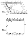
- Figures 1 and 2 respectively represent a manufactured gel plate in a cassette according to the invention, and the microporous membrane associated with this gel plate.
- the cassette of Figure 1 includes, like the cassette of the above-mentioned International Application WO93 / 01491 the content of which is incorporated here by reference, a framework rectangular 10 formed by two longitudinal uprights 12 interconnected at their ends by crossbars 14, and a removable bottom plate 16 (shown schematically in Figure 6) which is guided in grooves 18 of the internal faces of the longitudinal uprights 12 and which is provided at one of its ends a comb 20 carrying a row of teeth 22 intended for form wells 24 in the gel plate 26 produced at by means of the cassette, the bottom plate 16 being removed of the cassette when using the gel plate 26 for separation and transfer of macromolecules by electrophoresis.
- the microporous membrane 28 associated with the gel plate 26 is shown in Figure 2 and is formed a very thin film having for example a thickness of the order of 0.15 mm, a width of 170 mm and a length 225 mm in a particular embodiment, on the two longitudinal sides of which are fixed, by example by gluing or by welding, two bars 30 of plastic material having for example a thickness of in the order of a millimeter and a width of about 15 mm in a particular embodiment, and which include on the one hand, elongated orifices 32 for hooking on means of tensioning the membrane and on the other hand transverse slots 34 opening alternately on a edge and on the other of the bar 30 to allow a longitudinal extension thereof.
- the tensioning means of the membrane 28 are provided in the longitudinal uprights 12 of the frame 10 and understand, as best seen in the enlarged view in section of FIG. 3, pushers 36 guided in grooves 38 of the uprights 12 and the springs 40 housed in the grooves between the bottom of these and the pushers 36 to elastically urge the latter towards outside the frame 10.
- the pushers 36 include each, on their upper face, a pin 42 passing to through an elongated lumen 44 of the upper face of the amount 12 corresponding and intended to be engaged in a orifice 32 of a strip 30 of the membrane, for the attachment of the membrane to the tensioning means.
- the grooves 38 and the elongated lights 44 uprights 12 are radially oriented by relative to a fixed point 46 which is located on the longitudinal axis median of gel plate 26 and membrane 28, in the immediate vicinity of the edge of the gel plate with sinks 24.
- the grooves 38 for guiding the pushers 36 open to the outside of the uprights 12 in holes formed in two side bars 48 which are fixed on the outside faces of the uprights 12.
- the upper faces of the uprights 12 are inclined transversely outwards and downwards, as well as the grooves 38 for guiding the pushers 36, so that the membrane 28 can be properly applied on the edges formed by the internal longitudinal edges 50 of the amounts 12.
- the membrane thus prepared is then laid on the upper face of the frame 10 provided with the plate bottom 16.
- the pins 42 of the pushers 36 are engaged in the orifices 32 of the strips 30 of the membrane, which is then substantially uniform tensioning by the springs 40 elastically pushing the pushers 36 towards outside.
- the elongation of the membrane is around percent.
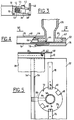
- the membrane delimits with the frame 10 and the bottom plate 16 a corresponding space exactly to the gel plate 26 to be manufactured and which is open only at the end of the frame 10 opposite to that closed by the comb 20 carried by the plate bottom 16. It is through this open end that the gel goes be poured in liquid form in this space, until the completely fill, using the device shown in Figures 4 and 5.
- This pouring device essentially comprises a support plate 52 intended to come to engage substantially sealed in the open end of the frame 10 between the bottom plate 16 and the membrane 28, the transverse front edge 54 of this support plate comprising an upper rib 56 forming an edge on which the membrane 28 applies.
- the casting device further comprises a vertical reservoir 58 substantially funnel-shaped, having a cylindrical base 60 engaged with very little play in a cylindrical housing 62 with the closed bottom of the support plate, such so that the base 60 of the tank can rotate in this housing around a vertical axis.
- a radial groove 64 is formed in the underside of the cylindrical base 60 of the tank, to communicate the interior of this tank with the cylindrical housing 62 formed in the support plate 52.
- a longitudinal duct 66 is formed in the support plate 52 to establish a communication between the cylindrical housing 62 and the front transverse edge 54 of the support plate.
- the base 60 of the reservoir 58 is held in the cylindrical housing 62 of the support plate by a bayonet mounting, by means of two diametrically 68 notches opposites formed in the periphery of the base 60 of the reservoir, and of two fingers 70 fixed in alignment on the upper face of the support plate 52, on the and on the other side of the axis of the cylindrical housing 62, the ends opposite the fingers 70 extending above and inward of cylindrical housing 62 over distances smaller than the dimensions of the notches 68 of the tank base.
- This pouring device is used in the way next :
- the reservoir 58 is first mounted on the support plate 52, its cylindrical base 60 being brought in the cylindrical housing 62 with the notches 68 aligned on the ends of fingers 70, then we do turn the base 60 of the tank in the cylindrical housing 62 so that the ends of the fingers 70 apply elastically to the upper face of the base 60 of the tank and keep it firmly in the cylindrical housing 62.
- Notches 72, 74 are advantageously formed on the upper face of the base 60, to receive a projection of corresponding shape provided at the end of the fingers 70 and determine precisely two angular positions of the reservoir 58 around its axis, the first angular position defined by the notches 72 being such that the groove 64 is not aligned with conduit 66 and is closed by the wall of the housing cylindrical 62, the second defined angular position by the notches 74 being such that the groove 64 is aligned with conduit 66 to allow liquid gel contained in the tank 58 to flow to inside the cassette.
- the support plate 52 is mounted in the end open the cassette as shown in the figures 4 and 5.
- a plate 76 comprising elastically deformable longitudinal fingers 78, can be fixed under the support plate 52 so that fingers 78 rest elastically on the underside of the bottom plate 16 to hold the device casting in place on the cassette.
- the membrane 28 can be mounted on the frame 10 before or after mounting the casting device on the frame.
- the end of the cassette containing the casting is slightly higher than its opposite end comprising the comb 20, due to the presence of the fixing plate 76, which creates a slight slope descending towards the comb 20.
- a dosed amount of liquid gel (for example agarose or polyacrylamide) is poured into the tank 58 and comes to fill the groove 64, expelling the air contained in this groove by the slight clearance between the periphery of base 60 and the cylindrical wall of the housing 62, this game having for example a value of the order 0.01 mm allowing air to escape while prohibiting the passage of liquid gel.
- liquid gel for example agarose or polyacrylamide
- the liquid gel thus gradually fills the space defined in box 10 between the plate bottom 16 and the tensioned membrane 28.
- the air contained in this space is gradually evacuated between the membrane 28 and the rib 56 of the support plate 52.
- the membrane 28 has tends to elongate, and this elongation is automatically gradually taken up by the tensioning means constituted by pushers 36 and associated springs 40.
- the pouring device When the gel is solidified, the pouring device from the end of the cassette into which he was engaged.
- This tool includes a support shelf 76 comprising positioning means (not shown) of the frame 10 provided with the bottom plate 16.
- This shelf 76 is equipped with means for repelling towards the inside of the frame the means of tensioning the membrane, so that it is sufficient to lay the membrane 28 provided with its two bars 30 on the top of the frame, so that the pins 42 of the tensioning means engage in the holes 32 of the bars.
- the means shown on the right side of Figure 6 which include movable fingers 86 guided in translation in the extension of the grooves 38 receiving the pushers 36, these fingers 86 comprising at their outer end a stud 88 engaged in a guide groove 90 of a zipper 92 extending along an upright 12 of the frame 8.
- the orientations of the grooves 90 of the pull tab 92 are such that when the zipper is moved in one direction the along the upright 12 of the frame, the fingers 86 are introduced in the guide grooves 38 of the pushers 36 and move these to the inside of the frame and, when the pull tab 92 is moved in the other direction, the fingers 86 have come out of the grooves 38 for guiding the pushers 36.
Landscapes
- Life Sciences & Earth Sciences (AREA)
- Chemical & Material Sciences (AREA)
- Health & Medical Sciences (AREA)
- Molecular Biology (AREA)
- Electrochemistry (AREA)
- Chemical Kinetics & Catalysis (AREA)
- Physics & Mathematics (AREA)
- Environmental & Geological Engineering (AREA)
- Engineering & Computer Science (AREA)
- Analytical Chemistry (AREA)
- Biochemistry (AREA)
- General Health & Medical Sciences (AREA)
- General Physics & Mathematics (AREA)
- Immunology (AREA)
- Pathology (AREA)
- Separation Using Semi-Permeable Membranes (AREA)
Abstract
Description
L'invention concerne un procédé et un dispositif de fabrication d'une place de gel à membrane microporeuse pour la séparation et le transfert de macromolécules par électrophorèse, le procédé et le dispositif utilisant une cassette comprenant un cadre rectangulaire et une plaque de fond amovible, dans laquelle le gel est coulé sous forme liquide.The invention relates to a method and a device for manufacturing a place of membrane gel microporous for the separation and transfer of macromolecules by electrophoresis, the process and the device using a cassette comprising a frame rectangular and a removable bottom plate, in which the gel is poured in liquid form.
On a déjà proposé, dans le document EP-A-0 499 546, de couler le gel liquide sous une membrane fixée préalablement sur un cadre rectangulaire posé lui-même sur une surface plane, ce qui évite les inconvénients liés à la coulée du gel sur une membrane posée sur une surface plane, tels que la traversée de la membrane par le gel qui s'accumule sur la surface de support et la présence de bulles d'air entre la membrane et le gel.We have already proposed, in the document EP-A-0 499 546, to pour the liquid gel under a membrane previously fixed on a rectangular frame placed itself on a flat surface, which avoids disadvantages of pouring gel onto a membrane placed on a flat surface, such as crossing the membrane by the gel that builds up on the surface of support and the presence of air bubbles between the membrane and frost.
On a également proposé, dans le document WO-A-93/01491, un procédé et un dispositif dans lesquels le gel sous forme liquide est tout d'abord coulé dans la cassette jusqu'à affleurer la face supérieure du cadre rectangulaire, après quoi on pose progressivement sur le gel et sur le cadre une membrane microporeuse sèche, on exerce une traction sur la périphérie de la membrane pour la tendre de façon sensiblement uniforme, et on laisse solidifier le gel en maintenant la membrane tendue.We also proposed in the document WO-A-93/01491, a method and a device in which the gel in liquid form is first poured into the cassette until flush with the top of the frame rectangular, after which we gradually lay on the gel and on the frame a dry microporous membrane, we pulls on the periphery of the membrane to tension it in a substantially uniform way, and let solidify the gel by keeping the membrane taut.
Ce procédé et ce dispositif permettent de fabriquer des plaques de gel dont une face est recouverte d'une membrane microporeuse adhérente, en général de nitrocellulose ou de "nylon", et qui satisfont à un certain nombre de critères tels que l'homogénéité du gel, la constance de son épaisseur, l'absence de bulles d'air entre le gel et la membrane, la planéité de la membrane et la propreté de la face libre de celle-ci. This process and this device make it possible to manufacture gel sheets with one side covered an adherent microporous membrane, generally nitrocellulose or "nylon", and which meet a certain number of criteria such as gel homogeneity, consistency of its thickness, the absence of air bubbles between the gel and the membrane, the flatness of the membrane and the cleanliness of the free face thereof.
Ce procédé et ce dispositif permettent également d'éviter certains inconvénients de la technique antérieure, tels que le débordement du gel sur la face libre de la membrane, ou la formation de plis sur la membrane résultant de l'allongement de celle-ci lors de son imprégnation par le gel.This method and this device also allow to avoid certain disadvantages of the technique anterior, such as gel overflow on the face free from the membrane, or the formation of folds on the membrane resulting from its elongation during its gel impregnation.
On a aussi proposé, dans le document EP-A-0 490 729, de couler le gel liquide sur une membrane soumise à une tension, ce qui évite ou réduit la formation de plis dans la membrane, mais n'empêche pas la traversée de la membrane par le gel et son accumulation sur la face libre de la membrane.We also proposed, in the document EP-A-0 490 729, pouring the liquid gel onto a membrane stressed, which avoids or reduces the formation of folds in the membrane, but does not prevent crossing of the membrane by the gel and its accumulation on the free face of the membrane.
La présente invention a pour objet des perfectionnements aux procédés et aux dispositifs décrits dans les documents antérieurs précités, ces perfectionnements permettant de simplifier et de rendre encore plus aisée la fabrication d'une plaque de gel à membrane microporeuse.The subject of the present invention is improvements to the methods and devices described in the aforementioned prior documents, these improvements to simplify and make even easier making a gel plate with microporous membrane.
L'invention propose donc un procédé de fabrication d'une plaque de gel à membrane microporeuse pour la séparation et le transfert de macromolécules par électrophorèse, le gel étant coulé sous forme liquide dans une cassette comprenant un cadre rectangulaire et une plaque de fond amovible et venant remplir l'espace délimité dans le cadre entre la plaque de fond et une membrane microporeuse préalablement fixée sur le cadre, caractérisé en ce qu'il consiste à mettre la membrane en tension de façon sensiblement uniforme en exerçant des forces de traction sur ses bords avant la coulée du gel et à maintenir la membrane sous tension pendant la solidification du gel, les forces de traction étant exercées en permanence sur deux bords opposés de la membrane, dans des directions rayonnantes à partir d'un point fixe situé sur un axe médian de la membrane, par exemple au voisinage d'un bord transversal de celle-ci. The invention therefore provides a manufacturing process a microporous membrane gel plate for separation and transfer of macromolecules by electrophoresis, the gel being poured in liquid form in a cassette comprising a rectangular frame and a removable bottom plate to fill the space delimited in the frame between the bottom plate and a microporous membrane previously fixed on the frame, characterized in that it consists in putting the membrane in substantially uniform tension by exerting tensile forces on its edges before the gel is poured and keep the membrane under tension during the solidification of the gel, the tensile forces being permanently exercised on two opposite edges of the membrane, in radiating directions from a fixed point located on a median axis of the membrane, by example in the vicinity of a transverse edge thereof.
Le procédé selon l'invention présente l'avantage que la membrane microporeuse est posée sur le cadre rectangulaire et mise sous tension avant coulée du gel liquide, ce qui est beaucoup plus simple et plus facile à réaliser que de déposer progressivement une membrane microporeuse sur une couche de gel liquideThe method according to the invention presents the advantage that the microporous membrane is laid on the rectangular frame and energized before casting liquid gel, which is much simpler and easier to realize that gradually depositing a membrane microporous on a layer of liquid gel
remplissant une cassette. Selon une autre caractéristique de l'invention, le procédé consiste également à couler le gel dans la cassette par une extrémité de celle-ci, cette extrémité étant opposée à celle comprenant un peigne porté par la plaque de fond pour former dans la plaque de gel des puits de réception d'échantillons de macromolécules.filling a cassette. According to another characteristic of the invention, the method also consists in casting the gel in the cassette by one end of it, this end being opposite to that comprising a comb carried by the bottom plate to form in the plate freezing of the wells for receiving macromolecule samples.
Avantageusement, l'extrémité de la cassette utilisée pour la coulée du gel est légèrement surélevée, ce qui permet de chasser progressivement l'air contenu entre la plaque de fond et la membrane au fur et à mesure de la coulée du gel, pour garantir l'absence de bulles d'air entre le gel et la membrane.Advantageously, the end of the cassette used for pouring the gel is slightly raised, which gradually expels the air between the bottom plate and the membrane as you go pouring the gel, to guarantee the absence of bubbles air between the gel and the membrane.
Pour faciliter la mise en tension de la membrane, le procédé selon l'invention consiste préalablement à fixer, par exemple par collage, deux barrettes longitudinalement extensibles sur les deux bords précités de la membrane, et à exercer les forces de traction precitées sur la membrane au moyen de poussoirs qui sont engagés dans des orifices desdites barrettes et sollicités élastiquement vers l'extérieur par des ressorts, les poussoirs et les ressorts étant logés dans des rainures de guidage formées dans les côtés correspondants du cadre.To facilitate the tensioning of the membrane, the method according to the invention consists beforehand to fix, for example by gluing, two bars longitudinally extendable on the two aforementioned edges of the membrane, and to exert the aforementioned tensile forces on the membrane by means of pushers which are engaged in orifices of said bars and elastically stressed outwards by springs, the pushers and the springs being housed in guide grooves formed in the sides framework correspondents.
La traction exercée en permanence sur les bords de la membrane permet notamment d'absorber l'allongement de la membrane résultant de son imprégnation par le gel liquide lors de la coulée de celui-ci, et garantit la planéité de la membrane. The traction permanently exerted on the edges of the membrane allows in particular to absorb elongation of the membrane resulting from its impregnation by the liquid gel when it is poured, and guarantees the flatness of the membrane.
L'invention propose également un dispositif de fabrication d'une plaque de gel à membrane microporeuse pour la séparation et le transfert de macromolécules par électrophorèse, comprenant une cassette formée d'un cadre rectangulaire et d'une plaque de fond, des moyens de fixation d'une membrane microporeuse sur le cadre et des moyens de coulée de gel liquide à l'intérieur du cadre sur la plaque de fond, les moyens de coulée étant montés à une extrémité de la cassette et comprenant un canal de passage de gel débouchant dans la cassette entre la plaque de fond et ne membrane fixée sur le cadre, caractérisé en ce que deux montants longitudinaux opposés du cadre comprennent des moyens de traction coopérant avec deux bords longitudinaux opposés de la membrane pour mettre celle-ci en tension de façon sensiblement uniforme avant la coulée du gel et en ce que les moyens de coulée du gel comprennent un réservoir porté par une plaque support destinée à être introduite à étanchéité dans une extrémité ouverte du cadre, le réservoir comportant une base cylindrique montée en rotation dans un logement cylindrique de la plaque support et formée avec un canal de sortie de gel destiné à être amené, par rotation, en communication avec un conduit de la plaque support dont les extrémités débouchent respectivement dans le logement cylindrique et à l'intérieur du cadre entre la plaque de fond et la membrane tendue.The invention also provides a device for manufacturing a microporous membrane gel plate for separation and transfer of macromolecules by electrophoresis, comprising a cassette formed by a frame rectangular and a bottom plate, means of fixation of a microporous membrane on the frame and means for pouring liquid gel inside the frame on the bottom plate, the casting means being mounted at one end of the cassette and comprising a channel passage of gel opening into the cassette between the bottom plate and no membrane attached to the frame, characterized in that two opposite longitudinal uprights of the frame include cooperating traction means with two opposite longitudinal edges of the membrane for tension it in a substantially uniform fashion before pouring the gel and in that the pouring means gel include a reservoir carried by a plate support intended to be introduced as a seal in a open end of the frame, the tank having a cylindrical base rotatably mounted in a housing cylindrical of the support plate and formed with a channel gel outlet intended to be brought, by rotation, in communication with a conduit of the support plate whose the ends open respectively into the housing cylindrical and inside the frame between the plate bottom and the membrane stretched.
Ce réservoir permet de doser préalablement la quantité de gel nécessaire à la fabrication d'une plaque de gel puis, par rotation sur la plaque support, d'autoriser l'écoulement dans la cassette de cette quantité dosée de gel.This tank makes it possible to dose the amount of gel needed to make a plate of gel then, by rotation on the support plate, allow this quantity to flow into the cassette dosed with gel.
La structure de ces moyens de coulée permet de plus de réaliser automatiquement un dégazage du gel et une évacuation de l'air contenu dans le canal de sortie du réservoir, avant la coulée du gel. The structure of these casting means makes it possible to more than automatically degassing the gel and an evacuation of the air contained in the outlet channel of the tank, before pouring the gel.
Les moyens de traction précités comprennent des poussoirs guidés dans des rainures des côtés précités du cadre et sollicités vers l'extérieur par des ressorts, ces poussoirs comportant des moyens d'accrochage des bords de la membrane.The aforementioned traction means include pushers guided in grooves on the aforementioned sides of the frame and stressed outwards by springs, these pushers comprising means for hooking the edges of the membrane.
Avantageusement, le dispositif comprend également des moyens agissant sur les poussoirs pour les déplacer vers l'intérieur du cadre dans le sens opposé à l'action des ressorts, dans une position permettant la pose sur la cassette d'une membrane non tendue et l'accrochage de cette membrane sur les poussoirs.Advantageously, the device comprises also means acting on the pushers for the move inward of the frame in the opposite direction to the action of the springs, in a position allowing the laying an untensioned membrane on the cassette and the attachment of this membrane on the pushers.
Dans un mode de réalisation préféré, le dispositif comprend une tablette de support et de positionnement de la cassette, et deux bras mobiles montés sur la tablette de part et d'autre de la cassette et portant des doigts destinés à être engagés dans les rainures de guidage des poussoirs, ces bras étant déplaçables entre une position active où les doigts sont engagés dans les rainures de guidage des poussoirs et repoussent ces derniers vers l'intérieur du cadre, et une position inactive où les doigts sont écartés des rainures de guidage des poussoirs.In a preferred embodiment, the device includes a support shelf and cassette positioning, and two movable arms mounted on the shelf on either side of the cassette and wearing fingers intended to be engaged in guide grooves for the pushers, these arms being movable between an active position where the fingers are engaged in the guide grooves of the pushers and push these towards the inside of the frame, and a inactive position where the fingers are separated from the grooves for guiding the pushers.
Ces moyens facilitent la pose d'une membrane et son accrochage sur les moyens de traction prévus sur le cadre d'une cassette. Les deux bras mobiles permettent en effet d'amener simultanément tous les moyens de traction dans des positions prédéterminées de réception d'une membrane.These means facilitate the installation of a membrane and its attachment to the traction means provided on the frame of a cassette. The two movable arms allow indeed to simultaneously bring all the means of traction in predetermined receiving positions of a membrane.
De façon générale, le procédé et le dispositif selon l'invention facilitent beaucoup la fabrication d'une plaque de gel à membrane microporeuse, de sorte que cette fabrication peut être effectuée à cadence élevée par du personnel non spécialisé, les plaques de gel ainsi fabriquées ayant des qualités homogènes et reproductibles. In general, the method and the device according to the invention greatly facilitate the manufacture a plate of microporous membrane gel, so that this production can be carried out at a high rate by non-specialized personnel, the gel plates as well manufactured with homogeneous and reproducible qualities.
L'invention sera mieux comprise et d'autres caractéristiques, détails et avantages de celle-ci apparaítront plus clairement à la lecture de la description qui suit, faite à titre d'exemple en référence aux dessins annexés dans lesquels :
- la figure 1 est une vue schématique en perspective d'une plaque de gel fabriquée dans une cassette selon l'invention, la membrane microporeuse étant retirée pour plus de clarté ;
- la figure 2 est une vue schématique en plan de la membrane microporeuse ;
- la figure 3 est une vue partielle en coupe, à plus grande échelle, d'un moyen de traction d'une membrane microporeuse ;
- la figure 4 est une vue partielle en coupe longitudinale des moyens de coulée de gel ;
- la figure 5 est une vue schématique partielle en coupe selon la ligne V-V de la figure 4 ;
- la figure 6 représente schématiquement deux formes de réalisation des moyens utilisés pour la pose d'une membrane sur une cassette.
- Figure 1 is a schematic perspective view of a gel plate made in a cassette according to the invention, the microporous membrane being removed for clarity;
- Figure 2 is a schematic plan view of the microporous membrane;
- Figure 3 is a partial sectional view, on a larger scale, of a traction means of a microporous membrane;
- Figure 4 is a partial view in longitudinal section of the gel casting means;
- Figure 5 is a partial schematic sectional view along the line VV of Figure 4;
- FIG. 6 schematically represents two embodiments of the means used for laying a membrane on a cassette.
On se réfère tout d'abord aux figures 1 et 2, qui représentent respectivement une plaque de gel fabriquée dans une cassette conformément à l'invention, et la membrane microporeuse associée à cette plaque de gel.We first refer to Figures 1 and 2, which respectively represent a manufactured gel plate in a cassette according to the invention, and the microporous membrane associated with this gel plate.
La cassette de la figure 1 comprend, comme la
cassette de la Demande Internationale WO93/01491 précitée
dont le contenu est incorporé ici par référence, un cadre
rectangulaire 10 formé de deux montants longitudinaux 12
reliés entre eux à leurs extrémités par des barres transversales
14, et une plaque de fond amovible 16
(représentée schématiquement en figure 6) qui est guidée
dans des rainures 18 des faces internes des montants longitudinaux
12 et qui est munie à l'une de ses extrémités
d'un peigne 20 portant une rangée de dents 22 destinées à
former des puits 24 dans la plaque de gel 26 fabriquée au
moyen de la cassette, la plaque de fond 16 étant retirée
de la cassette lorsqu'on utilise la plaque de gel 26 pour
la séparation et le transfert de macromolécules par électrophorèse.The cassette of Figure 1 includes, like the
cassette of the above-mentioned International Application WO93 / 01491
the content of which is incorporated here by reference, a framework
rectangular 10 formed by two
La membrane microporeuse 28 associée à la
plaque de gel 26 est représentée en figure 2 et est formée
d'un film très mince ayant par exemple une épaisseur
de l'ordre de 0,15 mm, une largeur de 170 mm et une longueur
de 225 mm dans un mode de réalisation particulier,
sur les deux côtés longitudinaux duquel sont fixées, par
exemple par collage ou par soudure, deux barrettes 30 de
matière plastique ayant par exemple une épaisseur de
l'ordre du millimètre et une largeur d'environ 15 mm dans
un mode de réalisation particulier, et qui comprennent
d'une part des orifices allongés 32 d'accrochage sur des
moyens de tension de la membrane et d'autre part des
fentes transversales 34 débouchant alternativement sur un
bord et sur l'autre de la barrette 30 pour permettre une
extension longitudinale de celle-ci.The
Les moyens de tension de la membrane 28 sont
prévus dans les montants longitudinaux 12 du cadre 10 et
comprennent, comme on le voit mieux sur la vue agrandie
en coupe de la figure 3, des poussoirs 36 guidés dans des
rainures 38 des montants 12 et des ressorts 40 logés dans
les rainures entre le fond de celles-ci et les poussoirs
36 pour solliciter élastiquement ces derniers vers
l'extérieur du cadre 10. Les poussoirs 36 comportent
chacun, sur leur face supérieure, un pion 42 passant à
travers une lumière allongée 44 de la face supérieure du
montant 12 correspondant et destiné à être engagé dans un
orifice 32 d'une barrette 30 de la membrane, pour
l'accrochage de la membrane sur les moyens de tension.The tensioning means of the
Les rainures 38 et les lumières allongées 44
des montants 12 sont orientées de façon rayonnante par
rapport à un point fixe 46 qui est situé sur l'axe longitudinal
médian de la plaque de gel 26 et de la membrane
28, au voisinage immédiat du bord de la plaque de gel
comportant les puits 24.The
Les rainures 38 de guidage des poussoirs 36
débouchent à l'extérieur des montants 12 dans des orifices
formés dans deux barrettes latérales 48 qui sont
fixées sur les faces extérieures des montants 12.The
Comme on le voit sur la vue agrandie de la figure
3, les faces supérieures des montants 12 sont inclinées
transversalement vers l'extérieur et vers le bas,
ainsi que les rainures 38 de guidage des poussoirs 36, de
telle sorte que la membrane 28 puisse être bien appliquée
sur les arêtes que forment les bords longitudinaux internes
50 des montants 12.As seen in the enlarged view of the figure
3, the upper faces of the
Pour la fabrication d'une plaque de gel conformément à l'invention, on procède de la façon suivante :For the production of a gel plate in accordance with the invention, the procedure is as follows :
On prépare tout d'abord la membrane microporeuse
28, sur les bords longitudinaux de laquelle on fixe
les barrettes 30 par collage ou par soudure, les bords
longitudinaux de la membrane s'étendant approximativement
le long des axes médians des barrettes 30 pour laisser
libres les orifices 32 de celles-ci.First prepare the
La membrane ainsi préparée est ensuite posée
sur la face supérieure du cadre 10 muni de la plaque de
fond 16. Les pions 42 des poussoirs 36 sont engagés dans
les orifices 32 des barrettes 30 de la membrane, qui est
alors mise en tension sensiblement uniforme par les ressorts
40 poussant élastiquement les poussoirs 36 vers
l'extérieur. L'allongement de la membrane est de l'ordre
du pour cent.The membrane thus prepared is then laid
on the upper face of the
Dans ces conditions, la membrane délimite avec
le cadre 10 et la plaque de fond 16 un espace correspondant
exactement à la plaque de gel 26 à fabriquer et qui
est ouvert uniquement à l'extrémité du cadre 10 opposée à
celle obturée par le peigne 20 porté par la plaque de
fond 16. C'est par cette extrémité ouverte que le gel va
être coulé sous forme liquide dans cet espace, jusqu'à le
remplir complètement, au moyen du dispositif représenté
dans les figures 4 et 5.Under these conditions, the membrane delimits with
the
Ce dispositif de coulée comprend essentiellement
une plaque support 52 destinée à venir s'engager
sensiblement à étanchéité dans l'extrémité ouverte du
cadre 10 entre la plaque de fond 16 et la membrane 28, le
bord avant transversal 54 de cette plaque support comportant
une nervure supérieure 56 formant une arête sur laquelle
la membrane 28 s'applique. Le dispositif de coulée
comprend encore un réservoir vertical 58 sensiblement
en forme d'entonnoir, comportant une base cylindrique 60
engagée avec un jeu très faible dans un logement cylindrique
62 à fond fermé de la plaque support, de telle
sorte que la base 60 du réservoir puisse tourner dans ce
logement autour d'un axe vertical. Une rainure radiale
64 est formée dans la face inférieure de la base cylindrique
60 du réservoir, pour faire communiquer
l'intérieur de ce réservoir avec le logement cylindrique
62 formé dans la plaque support 52. Un conduit longitudinal
66 est formé dans la plaque support 52 pour établir
une communication entre le logement cylindrique 62 et le
bord transversal avant 54 de la plaque support.This pouring device essentially comprises
a
La base 60 du réservoir 58 est maintenue dans
le logement cylindrique 62 de la plaque support par un
montage à baïonnette, au moyen de deux encoches 68 diamétralement
opposées formées dans la périphérie de la base
60 du réservoir, et de deux doigts 70 fixés en alignement
sur la face supérieure de la plaque support 52, de part
et d'autre de l'axe du logement cylindrique 62, les extrémités
en regard des doigts 70 s'étendant au-dessus et
vers l'intérieur du logement cylindrique 62 sur des distances
inférieures aux dimensions des encoches 68 de la
base du réservoir.The
Ce dispositif de coulée est utilisé de la façon suivante :This pouring device is used in the way next :
Le réservoir 58 est tout d'abord monté sur la
plaque support 52, sa base cylindrique 60 étant amenée
dans le logement cylindrique 62 avec les encoches 68 alignées
sur les extrémités des doigts 70, puis on fait
tourner la base 60 du réservoir dans le logement cylindrique
62 de façon à ce que les extrémités des doigts 70
s'appliquent élastiquement sur la face supérieure de la
base 60 du réservoir et la maintiennent fermement dans le
logement cylindrique 62. Des crans 72, 74 sont avantageusement
formés sur la face supérieure de la base 60,
pour recevoir une saillie de forme correspondante prévue
à l'extrémité des doigts 70 et déterminer de façon précise
deux positions angulaires du réservoir 58 autour de
son axe, la première position angulaire définie par les
crans 72 étant telle que la rainure 64 n'est pas alignée
avec le conduit 66 et est obturée par la paroi du logement
cylindrique 62, la seconde position angulaire définie
par les crans 74 étant telle que la rainure 64 est
alignée avec le conduit 66 pour permettre à du gel liquide
contenu dans le réservoir 58 de s'écouler à
l'intérieur de la cassette.The
Lorsque le réservoir 58 a été ainsi monté sur
la plaque de fond 52 et amené dans la position angulaire
définie par les crans 72 dans laquelle la rainure 64 est
obturée, la plaque support 52 est montée dans l'extrémité
ouverte de la cassette comme représenté dans les figures
4 et 5.When the
Avantageusement, une plaque 76 comportant des
doigts longitudinaux 78 élastiquement déformables, peut
être fixée sous la plaque support 52 de telle sorte que
les doigts 78 s'appuient élastiquement sur la face inférieure
de la plaque de fond 16 pour maintenir le dispositif
de coulée en place sur la cassette.Advantageously, a
La membrane 28 peut être montée sur le cadre
10 avant ou après montage du dispositif de coulée sur le
cadre.The
Lorsque l'ensemble cassette-dispositif de coulée
est posé sur une surface de support horizontale,
l'extrémité de la cassette comportant le dispositif de
coulée est légèrement plus haute que son extrémité opposée
comportant le peigne 20, en raison de la présence de
la plaque de fixation 76, ce qui crée une faible pente
descendante en direction du peigne 20.When the cassette-casting device assembly
is placed on a horizontal support surface,
the end of the cassette containing the
casting is slightly higher than its opposite end
comprising the
Une quantité dosée de gel liquide (par exemple
d'agarose ou de polyacrylamide) est versée dans le réservoir
58 et vient remplir la rainure 64, en chassant l'air
contenu dans cette rainure par le jeu faible entre la périphérie
de la base 60 et la paroi cylindrique du logement
62, ce jeu ayant par exemple une valeur de l'ordre
de 0,01 mm ce qui permet à l'air de s'échapper tout en
interdisant le passage du gel liquide.A dosed amount of liquid gel (for example
agarose or polyacrylamide) is poured into the
Il suffit ensuite de tourner le réservoir 58
autour de son axe et de l'amener dans la seconde position
angulaire définie par les crans 74, pour que le gel liquide
puisse s'écouler du réservoir à l'intérieur de la
cassette en passant par la rainure 64 et le conduit 66.Then just turn the
Le gel liquide vient ainsi remplir progressivement
l'espace défini dans le cadre 10 entre la plaque
de fond 16 et la membrane tendue 28. L'air contenu dans
cet espace est progressivement évacué entre la membrane
28 et la nervure 56 de la plaque support 52. Au cours de
son imprégnation par le gel liquide, la membrane 28 a
tendance à s'allonger, et cet allongement est automatiquement
repris au fur et à mesure par les moyens de tension
constitués par les poussoirs 36 et les ressorts associés
40.The liquid gel thus gradually fills
the space defined in
Lorsque le gel liquide a rempli l'espace défini
dans le cadre 10 entre la plaque de fond 16 et la
membrane tendue 28, il monte sur le bord transversal
avant 54 de la plaque support 52, ce bord avant 54 étant
biseauté pour faciliter l'évacuation de l'air, et il
vient affleurer la nervure 56 sur laquelle s'applique la
membrane 28 mouillée par le gel. On arrête alors la coulée
du gel, s'il en reste encore dans le réservoir 58,
par rotation de ce réservoir pour l'amener dans sa première
position angulaire définie par les crans 72, et on
laisse solidifier le gel, par refroidissement à température
ambiante (gel d'agarose) ou par polymérisation (gel
de polyacrylamide).When the liquid gel has filled the defined space
in
Lorsque le gel est solidifié, on retire le dispositif de coulée de l'extrémité de la cassette dans laquelle il était engagé.When the gel is solidified, the pouring device from the end of the cassette into which he was engaged.
Pour utiliser ensuite la plaque de gel revêtue
de la membrane, on dispose l'ensemble cadre 10 - plaque
de gel 26 - membrane 28 verticalement dans une cuve
d'électrophorèse, on retire la plaque de fond 16 et on
dépose des échantillons de macromolécules dans les puits
24 de la plaque de gel.To then use the coated gel plate
of the membrane, we have the frame 10 - plate assembly
gel 26 -
On constate que le procédé et le dispositif selon l'invention permettent à du personnel non spécialisé de fabriquer rapidement des plaques de gel à membrane microporeuse ayant une très bonne qualité, parfaitement reproductible.We see that the process and the device according to the invention allow non-specialized personnel quickly fabricate membrane gel plates microporous having a very good quality, perfectly reproducible.
Cette fabrication peut être encore facilitée
par usage de l'outillage représenté schématiquement en
figure 6, qui permet une fixation simple, rapide et aisée
de la membrane sur le cadre 10 de la cassette.This can be made even easier
by using the tools shown schematically in
Figure 6, which allows simple, quick and easy attachment
of the membrane on the
Cet outillage comprend une tablette de support
76 comportant des moyens de positionnement (non représentés)
du cadre 10 muni de la plaque de fond 16. Cette tablette
76 est équipée de moyens permettant de repousser
vers l'intérieur du cadre les moyens de tension de la
membrane, de telle sorte qu'il suffit alors de poser la
membrane 28 munie de ses deux barrettes 30 sur le dessus
du cadre, pour que les pions 42 des moyens de tension
s'engagent dans les orifices 32 des barrettes.This tool includes a
Ces moyens permettant de déplacer les moyens
de tension, c'est-à-dire les poussoirs 36, vers
l'intérieur du cadre en comprimant les ressorts associés
40, peuvent être de différentes formes. Sur la partie
gauche de la figure 6, on a représenté un levier coudé 78
articulé autour d'un axe 80 et dont un bras 82 s'étend le
long d'un montant 12 du cadre, à l'extérieur de celui-ci,
et porte des doigts obliques 84 qui viennent s'engager
dans les rainures 38 de guidage des poussoirs 36 quand on
fait pivoter le levier 78 autour de l'axe 80 dans le sens
contraire des aiguilles d'une montre. Les longueurs des
doigts 84 sont telles que, quand le bras 82 du levier est
appliqué sur le cadre, les pions 42 des poussoirs sont
automatiquement amenés dans une position d'engagement
dans les orifices 32 d'une barrette 30 d'une membrane.These means making it possible to move the means
tension, i.e. pushers 36, towards
inside the frame by compressing the associated springs
40, can be of different shapes. On the party
left of Figure 6, there is shown a
En variante, on peut utiliser les moyens représentés
sur la partie droite de la figure 6, qui comprennent
des doigts mobiles 86 guidés en translation dans
le prolongement des rainures 38 recevant les poussoirs
36, ces doigts 86 comportant à leur extrémité extérieure
un téton 88 engagé dans une rainure de guidage 90 d'une
tirette 92 s'étendant le long d'un montant 12 du cadre 8.
Les orientations des rainures 90 de la tirette 92 sont
telles que, quand la tirette est déplacée dans un sens le
long du montant 12 du cadre, les doigts 86 sont introduits
dans les rainures de guidage 38 des poussoirs 36 et
déplacent ces derniers vers l'intérieur du cadre et,
quand la tirette 92 est déplacée dans l'autre sens, les
doigts 86 sont sortis des rainures 38 de guidage des
poussoirs 36.Alternatively, one can use the means shown
on the right side of Figure 6, which include
Claims (9)
- A method of making a gel plate with a microporous membrane for separating and transferring macromolecules by electrophoresis, the gel being poured in liquid form into a cassette comprising a rectangular frame (10) and a removable bottom plate (16), and filling the space defined in the frame (10) between the bottom plate and a microporous membrane (28) previously fixed on the frame (10), the method being characterized in that the method consists in putting the membrane (28) under tension in substantially uniform manner by exerting traction forces on its edges before pouring in the liquid gel and keeping the membrane (28) under tension during solidification of the gel, the traction forces being applied continuously to two opposite edges of the membrane (28) in directions radiating from a fixed point (46) located on a median axis of the membrane, for example in the vicinity of a transverse edge thereof.
- A method according to claim 1, characterized in that it consists in pouring the gel into the cassette via one end thereof, this end being opposite the end having a comb (20) on the bottom plate (16) for forming wells in the gel plate for receiving samples of macromolecules.
- A method according to claim 1 or 2, characterized in that it consists initially in fixing two extensible longitudinal strips (30) on the two said sides of the membrane (28), for example by adhesive, and in exerting the traction forces on the membrane by means of pushers (36, 42) engaged in holes (32) in said strips and urged resiliently outwards by springs (40), the pushers and the springs being fitted in guide grooves (38) formed in corresponding rails (12) of the frame.
- Apparatus for making a gel plate with a microporous membrane for separation and transfer of macromolecules by electrophoresis, the apparatus comprising a cassette formed by a rectangular frame (10) and a bottom plate (16), fixing means for fixing a microporous membrane (28) on the frame (10), and gel pouring means for pouring liquid gel into the interior of the cassette onto the bottom plate, the pouring means (52, 58) being mounted at one end of the cassette and comprising a channel (64, 66) for the gel opening into the cassette between the bottom plate (16) and a membrane (28) fixed on the frame, the apparatus being characterized in that two opposite longitudinal rails (12) of the frame comprise traction means (36, 40, 42) which cooperate with two opposite longitudinal edges of the membrane (28) for placing the latter under tension in substantially uniform manner, before pouring in the gel, and in that the gel pouring means comprise a tank (58) carried by a support plate (52) for sealed introduction into one open end of the frame (10), the tank comprising a cylindrical bottom part (60) mounted to rotate in a cylindrical seat (62) of the support plate and formed with an outlet channel (64) for the gel adapted to be placed by rotation in communication with a duct (66) in the support plate, the ends of the duct opening respectively into the cylindrical housing (62) and the interior of the frame between the bottom plate (16) and the tensioned membrane (28).
- Apparatus according to claim 4, characterized in that the traction means comprise pushers (36) guided in grooves (38) in said rails and urged towards the outside by springs (40), the pushers including means (42) for engaging the edges of the membrane (28).
- Apparatus according to claim 5, characterized in that the pushers (36) comprise lugs (42) adapted to be fitted into holes (32) formed in longitudinally extensible strips (30), which are fixed on the aforesaid edges of the membrane (28).
- Apparatus according to claim 5 or 6, characterized in that it comprises means (78, 82; 84, 86-92) acting on the pushers (36) for shifting them towards the interior of the frame, against the action of the springs (40), into a position allowing a non-tensioned membrane (28) to be placed on the cassette and the engagement of this membrane on the pushers.
- Apparatus according to claim 7, characterized in that it comprises a support table (76) for positioning the cassette and two movable arms (78, 92) mounted on the table on either side of the cassette and carrying fingers (84, 86) adapted to be engaged in the guide grooves (38) of the pushers, these arms being movable between an active position in which the fingers are engaged in the guide grooves of the pushers and push them towards the interior of the cassette, and an inactive position in which the fingers are retracted from the guide grooves of the pushers.
- Apparatus according to any one of claims 4 to 8, characterized in that the removable bottom plate (16) of the cassette comprises, at one of its ends, a comb (20) for forming wells (24) in the gel plate, this comb closing the end of the frame (10) opposite the end receiving the pouring means in sealed manner.
Applications Claiming Priority (2)
| Application Number | Priority Date | Filing Date | Title |
|---|---|---|---|
| FR9212004 | 1992-10-09 | ||
| FR9212004A FR2696657B1 (en) | 1992-10-09 | 1992-10-09 | Method and device for manufacturing a gel plate with a microporous membrane for the separation and transfer of macromolecules by electrophoresis. |
Publications (2)
| Publication Number | Publication Date |
|---|---|
| EP0592298A1 EP0592298A1 (en) | 1994-04-13 |
| EP0592298B1 true EP0592298B1 (en) | 1998-01-21 |
Family
ID=9434319
Family Applications (1)
| Application Number | Title | Priority Date | Filing Date |
|---|---|---|---|
| EP93402437A Expired - Lifetime EP0592298B1 (en) | 1992-10-09 | 1993-10-05 | Process and device for the manufacture of a microporous membrane gel plate for separating and transforming macromolecules by electrophoresis |
Country Status (9)
| Country | Link |
|---|---|
| US (1) | US5482613A (en) |
| EP (1) | EP0592298B1 (en) |
| JP (1) | JPH07502124A (en) |
| AT (1) | ATE162422T1 (en) |
| AU (1) | AU5115993A (en) |
| CA (1) | CA2124959A1 (en) |
| DE (1) | DE69316506D1 (en) |
| FR (1) | FR2696657B1 (en) |
| WO (1) | WO1994008701A1 (en) |
Families Citing this family (12)
| Publication number | Priority date | Publication date | Assignee | Title |
|---|---|---|---|---|
| WO1996009537A1 (en) * | 1994-09-19 | 1996-03-28 | Novel Experimental Technology | Plastic mold for electrophoresis gel |
| DE19949462A1 (en) * | 1999-10-14 | 2001-04-19 | Universitaetsklinikum Freiburg | Molding press for electrophoresis gels has a manual drive system for moving pressure plates onto the sides of an open mold and springs for applying closure pressure |
| DE10063096C1 (en) * | 2000-12-18 | 2002-09-12 | Gerhard Weber | Electrophoresis device, electrophoresis method using an electrophoresis device and using the electrophoresis device |
| US20040079641A1 (en) * | 2002-10-02 | 2004-04-29 | Qi-Feng Ma | Curved-film mold for preparation of electrophoresis gels |
| WO2006091525A2 (en) * | 2005-02-24 | 2006-08-31 | Invitrogen Corporation | Electro-blotting devices, systems, and kits, and methods for their use |
| EP2310857A4 (en) | 2008-07-11 | 2011-11-30 | Life Technologies Corp | Electrophoretically enhanced detection of analytes on a solid support |
| US8715476B2 (en) | 2009-12-11 | 2014-05-06 | Bio-Rad Laboratories, Inc. | Instrument for independent electrotransfer in multiple cassettes |
| EP2856132A4 (en) | 2012-05-31 | 2016-05-18 | Ge Healthcare Bio Sciences Ab | Electrophoresis gel cassette and a method of filling an electrophoresis gel cassette. |
| US9594054B2 (en) | 2012-07-25 | 2017-03-14 | Bio-Rad Laboratories, Inc. | Targeted delivery of reagents to spots on a planar support through patterned transfer sheets |
| CN104937401B (en) | 2012-10-17 | 2018-03-09 | 生物辐射实验室股份有限公司 | Image capture for big analyte array |
| US9291596B2 (en) | 2013-02-12 | 2016-03-22 | Pierce Biotechnology, Inc. | Electroblot transfer buffer |
| USD738527S1 (en) | 2013-05-28 | 2015-09-08 | Life Technologies Corporation | Electroblotting apparatus |
Family Cites Families (2)
| Publication number | Priority date | Publication date | Assignee | Title |
|---|---|---|---|---|
| FR2670129B1 (en) * | 1990-12-10 | 1993-04-02 | Bertin & Cie | PROCESS FOR THE PREPARATION OF A MEMBRANE FILLED WITH A LAYER OF A GEL AND SUPPORT FRAME OF SUCH A MEMBRANE DESIGNED FOR THE IMPLEMENTATION OF THIS PROCESS. |
| FR2672822B1 (en) * | 1991-02-14 | 1993-06-11 | Bertin & Cie | METHOD OF MANUFACTURING A GEL PLATE FOR THE SEPARATION AND TRANSFER OF MACROMOLECULES BY ELECTROPHORESIS, AND THE GEL PLATES THUS OBTAINED. |
-
1992
- 1992-10-09 FR FR9212004A patent/FR2696657B1/en not_active Expired - Fee Related
-
1993
- 1993-10-05 US US08/244,528 patent/US5482613A/en not_active Expired - Fee Related
- 1993-10-05 EP EP93402437A patent/EP0592298B1/en not_active Expired - Lifetime
- 1993-10-05 JP JP6509692A patent/JPH07502124A/en active Pending
- 1993-10-05 CA CA002124959A patent/CA2124959A1/en not_active Abandoned
- 1993-10-05 AT AT93402437T patent/ATE162422T1/en not_active IP Right Cessation
- 1993-10-05 DE DE69316506T patent/DE69316506D1/en not_active Expired - Lifetime
- 1993-10-05 WO PCT/FR1993/000982 patent/WO1994008701A1/en active Application Filing
- 1993-10-05 AU AU51159/93A patent/AU5115993A/en not_active Abandoned
Also Published As
| Publication number | Publication date |
|---|---|
| FR2696657A1 (en) | 1994-04-15 |
| AU5115993A (en) | 1994-05-09 |
| EP0592298A1 (en) | 1994-04-13 |
| WO1994008701A1 (en) | 1994-04-28 |
| CA2124959A1 (en) | 1994-04-28 |
| US5482613A (en) | 1996-01-09 |
| JPH07502124A (en) | 1995-03-02 |
| FR2696657B1 (en) | 1995-01-13 |
| ATE162422T1 (en) | 1998-02-15 |
| DE69316506D1 (en) | 1998-02-26 |
Similar Documents
| Publication | Publication Date | Title |
|---|---|---|
| EP0592298B1 (en) | Process and device for the manufacture of a microporous membrane gel plate for separating and transforming macromolecules by electrophoresis | |
| EP0941928B1 (en) | Method and machine for making bags with a transverse zipper | |
| FR2555975A1 (en) | APPARATUS FOR DISTRIBUTION AND SIMULTANEOUS CUTTING OF BANDS OF ROLLING MATERIALS, WITH AT LEAST ONE ROLL OF MATERIAL IN SERVICE | |
| CH675404A5 (en) | ||
| FR2600245A1 (en) | URINOMETER AND DEVICE FOR COLLECTING URINE | |
| CA2386421A1 (en) | Device for distributing wiping material | |
| EP0151377A1 (en) | Device for filling cigarette paper tubes | |
| EP0612476B1 (en) | Device for making sandwiches | |
| FR2583729A1 (en) | Simplified apparatus for simultaneously delivering and cutting strips of wound materials with automatic changing of the roller in use | |
| BE1004855A5 (en) | Mechanism of progress sheet roll machine for automatic draw type paper drive. | |
| EP0548335B1 (en) | Process and device for the manufacture of a microporous membrane gel plate and gel cassette | |
| EP0343285A1 (en) | Cord unrolling device for tomato culture | |
| FR2650559A1 (en) | Device and method for automatically bagging materials | |
| WO2006021701A1 (en) | Device for loading rolls of wiping materials in an automatic-strip-cutting dispenser | |
| EP1944239A1 (en) | Method for preparing packaging for flower and/or plant arrangements | |
| CA1327682C (en) | Process for replacing the product to be introduced in thermoplastic containers and at least one decorative and/or informative element on said containers, mechanism for joining strips, and apparatus used for the implementation of the process | |
| EP0173633B1 (en) | Machine for loading and cutting at least one extremity of a sousage casing and similar products | |
| EP0064014A1 (en) | Slide frame | |
| BE1000663A5 (en) | Liquid collection device or urine meter - has flexible-walled container screwed to top of receptacle and provided with inlet conduit | |
| FR2754521A1 (en) | Carrier for bottles with tear tabs | |
| FR2942831A1 (en) | Apparatus for coating paper tape on gypsum board joint to form e.g. dry partition between rooms, has scraper mounted above roller for partially stripping plaster present on surface of tape coming from roller when tape passes through slot | |
| BE843137A (en) | METHOD AND DEVICE FOR EMPTYING A TANK OF TEXTILES OR OTHER FIBROUS MATERIALS | |
| BE559534A (en) | ||
| FR2679886A1 (en) | APPARATUS FOR DISTRIBUTING AND SIMULTANEOUSLY CUTTING TAPES OF WOUND MATERIALS. | |
| EP0298178A1 (en) | Method and gauge for making a truss |
Legal Events
| Date | Code | Title | Description |
|---|---|---|---|
| PUAI | Public reference made under article 153(3) epc to a published international application that has entered the european phase |
Free format text: ORIGINAL CODE: 0009012 |
|
| AK | Designated contracting states |
Kind code of ref document: A1 Designated state(s): AT BE CH DE DK ES FR GB GR IT LI LU MC NL SE |
|
| 17P | Request for examination filed |
Effective date: 19940920 |
|
| 17Q | First examination report despatched |
Effective date: 19950822 |
|
| GRAG | Despatch of communication of intention to grant |
Free format text: ORIGINAL CODE: EPIDOS AGRA |
|
| GRAH | Despatch of communication of intention to grant a patent |
Free format text: ORIGINAL CODE: EPIDOS IGRA |
|
| GRAH | Despatch of communication of intention to grant a patent |
Free format text: ORIGINAL CODE: EPIDOS IGRA |
|
| GRAA | (expected) grant |
Free format text: ORIGINAL CODE: 0009210 |
|
| AK | Designated contracting states |
Kind code of ref document: B1 Designated state(s): AT BE CH DE DK ES FR GB GR IT LI LU MC NL SE |
|
| PG25 | Lapsed in a contracting state [announced via postgrant information from national office to epo] |
Ref country code: NL Free format text: LAPSE BECAUSE OF FAILURE TO SUBMIT A TRANSLATION OF THE DESCRIPTION OR TO PAY THE FEE WITHIN THE PRESCRIBED TIME-LIMIT Effective date: 19980121 Ref country code: IT Free format text: LAPSE BECAUSE OF FAILURE TO SUBMIT A TRANSLATION OF THE DESCRIPTION OR TO PAY THE FEE WITHIN THE PRESCRIBED TIME-LIMIT;WARNING: LAPSES OF ITALIAN PATENTS WITH EFFECTIVE DATE BEFORE 2007 MAY HAVE OCCURRED AT ANY TIME BEFORE 2007. THE CORRECT EFFECTIVE DATE MAY BE DIFFERENT FROM THE ONE RECORDED. Effective date: 19980121 Ref country code: GR Free format text: LAPSE BECAUSE OF FAILURE TO SUBMIT A TRANSLATION OF THE DESCRIPTION OR TO PAY THE FEE WITHIN THE PRESCRIBED TIME-LIMIT Effective date: 19980121 Ref country code: GB Free format text: LAPSE BECAUSE OF FAILURE TO SUBMIT A TRANSLATION OF THE DESCRIPTION OR TO PAY THE FEE WITHIN THE PRESCRIBED TIME-LIMIT Effective date: 19980121 Ref country code: ES Free format text: THE PATENT HAS BEEN ANNULLED BY A DECISION OF A NATIONAL AUTHORITY Effective date: 19980121 Ref country code: AT Free format text: LAPSE BECAUSE OF FAILURE TO SUBMIT A TRANSLATION OF THE DESCRIPTION OR TO PAY THE FEE WITHIN THE PRESCRIBED TIME-LIMIT Effective date: 19980121 |
|
| REF | Corresponds to: |
Ref document number: 162422 Country of ref document: AT Date of ref document: 19980215 Kind code of ref document: T |
|
| REG | Reference to a national code |
Ref country code: CH Ref legal event code: EP |
|
| REF | Corresponds to: |
Ref document number: 69316506 Country of ref document: DE Date of ref document: 19980226 |
|
| PG25 | Lapsed in a contracting state [announced via postgrant information from national office to epo] |
Ref country code: SE Free format text: LAPSE BECAUSE OF FAILURE TO SUBMIT A TRANSLATION OF THE DESCRIPTION OR TO PAY THE FEE WITHIN THE PRESCRIBED TIME-LIMIT Effective date: 19980421 Ref country code: DK Free format text: LAPSE BECAUSE OF FAILURE TO SUBMIT A TRANSLATION OF THE DESCRIPTION OR TO PAY THE FEE WITHIN THE PRESCRIBED TIME-LIMIT Effective date: 19980421 |
|
| PG25 | Lapsed in a contracting state [announced via postgrant information from national office to epo] |
Ref country code: DE Free format text: LAPSE BECAUSE OF FAILURE TO SUBMIT A TRANSLATION OF THE DESCRIPTION OR TO PAY THE FEE WITHIN THE PRESCRIBED TIME-LIMIT Effective date: 19980422 |
|
| NLV1 | Nl: lapsed or annulled due to failure to fulfill the requirements of art. 29p and 29m of the patents act | ||
| GBV | Gb: ep patent (uk) treated as always having been void in accordance with gb section 77(7)/1977 [no translation filed] |
Effective date: 19980121 |
|
| PG25 | Lapsed in a contracting state [announced via postgrant information from national office to epo] |
Ref country code: LU Free format text: LAPSE BECAUSE OF NON-PAYMENT OF DUE FEES Effective date: 19981005 |
|
| PG25 | Lapsed in a contracting state [announced via postgrant information from national office to epo] |
Ref country code: LI Free format text: LAPSE BECAUSE OF NON-PAYMENT OF DUE FEES Effective date: 19981031 Ref country code: CH Free format text: LAPSE BECAUSE OF NON-PAYMENT OF DUE FEES Effective date: 19981031 Ref country code: BE Free format text: LAPSE BECAUSE OF NON-PAYMENT OF DUE FEES Effective date: 19981031 |
|
| PLBE | No opposition filed within time limit |
Free format text: ORIGINAL CODE: 0009261 |
|
| STAA | Information on the status of an ep patent application or granted ep patent |
Free format text: STATUS: NO OPPOSITION FILED WITHIN TIME LIMIT |
|
| 26N | No opposition filed | ||
| BERE | Be: lapsed |
Owner name: BERTIN & CIE Effective date: 19981031 |
|
| PG25 | Lapsed in a contracting state [announced via postgrant information from national office to epo] |
Ref country code: MC Free format text: LAPSE BECAUSE OF NON-PAYMENT OF DUE FEES Effective date: 19990430 |
|
| REG | Reference to a national code |
Ref country code: CH Ref legal event code: PL |
|
| PG25 | Lapsed in a contracting state [announced via postgrant information from national office to epo] |
Ref country code: FR Free format text: LAPSE BECAUSE OF NON-PAYMENT OF DUE FEES Effective date: 19990630 |
|
| REG | Reference to a national code |
Ref country code: FR Ref legal event code: ST |