EP0592221A1 - Druckkopf mit verminderten Verbindungen zu einem Drucker - Google Patents
Druckkopf mit verminderten Verbindungen zu einem Drucker Download PDFInfo
- Publication number
- EP0592221A1 EP0592221A1 EP93307989A EP93307989A EP0592221A1 EP 0592221 A1 EP0592221 A1 EP 0592221A1 EP 93307989 A EP93307989 A EP 93307989A EP 93307989 A EP93307989 A EP 93307989A EP 0592221 A1 EP0592221 A1 EP 0592221A1
- Authority
- EP
- European Patent Office
- Prior art keywords
- printhead
- signal
- interconnection
- address
- Prior art date
- Legal status (The legal status is an assumption and is not a legal conclusion. Google has not performed a legal analysis and makes no representation as to the accuracy of the status listed.)
- Granted
Links
Images


Classifications
-
- B—PERFORMING OPERATIONS; TRANSPORTING
- B41—PRINTING; LINING MACHINES; TYPEWRITERS; STAMPS
- B41J—TYPEWRITERS; SELECTIVE PRINTING MECHANISMS, i.e. MECHANISMS PRINTING OTHERWISE THAN FROM A FORME; CORRECTION OF TYPOGRAPHICAL ERRORS
- B41J2/00—Typewriters or selective printing mechanisms characterised by the printing or marking process for which they are designed
- B41J2/005—Typewriters or selective printing mechanisms characterised by the printing or marking process for which they are designed characterised by bringing liquid or particles selectively into contact with a printing material
- B41J2/01—Ink jet
- B41J2/015—Ink jet characterised by the jet generation process
- B41J2/04—Ink jet characterised by the jet generation process generating single droplets or particles on demand
- B41J2/045—Ink jet characterised by the jet generation process generating single droplets or particles on demand by pressure, e.g. electromechanical transducers
- B41J2/04501—Control methods or devices therefor, e.g. driver circuits, control circuits
- B41J2/04521—Control methods or devices therefor, e.g. driver circuits, control circuits reducing number of signal lines needed
-
- B—PERFORMING OPERATIONS; TRANSPORTING
- B41—PRINTING; LINING MACHINES; TYPEWRITERS; STAMPS
- B41J—TYPEWRITERS; SELECTIVE PRINTING MECHANISMS, i.e. MECHANISMS PRINTING OTHERWISE THAN FROM A FORME; CORRECTION OF TYPOGRAPHICAL ERRORS
- B41J2/00—Typewriters or selective printing mechanisms characterised by the printing or marking process for which they are designed
- B41J2/005—Typewriters or selective printing mechanisms characterised by the printing or marking process for which they are designed characterised by bringing liquid or particles selectively into contact with a printing material
- B41J2/01—Ink jet
- B41J2/015—Ink jet characterised by the jet generation process
- B41J2/04—Ink jet characterised by the jet generation process generating single droplets or particles on demand
- B41J2/045—Ink jet characterised by the jet generation process generating single droplets or particles on demand by pressure, e.g. electromechanical transducers
- B41J2/04501—Control methods or devices therefor, e.g. driver circuits, control circuits
- B41J2/04541—Specific driving circuit
-
- B—PERFORMING OPERATIONS; TRANSPORTING
- B41—PRINTING; LINING MACHINES; TYPEWRITERS; STAMPS
- B41J—TYPEWRITERS; SELECTIVE PRINTING MECHANISMS, i.e. MECHANISMS PRINTING OTHERWISE THAN FROM A FORME; CORRECTION OF TYPOGRAPHICAL ERRORS
- B41J2/00—Typewriters or selective printing mechanisms characterised by the printing or marking process for which they are designed
- B41J2/005—Typewriters or selective printing mechanisms characterised by the printing or marking process for which they are designed characterised by bringing liquid or particles selectively into contact with a printing material
- B41J2/01—Ink jet
- B41J2/015—Ink jet characterised by the jet generation process
- B41J2/04—Ink jet characterised by the jet generation process generating single droplets or particles on demand
- B41J2/045—Ink jet characterised by the jet generation process generating single droplets or particles on demand by pressure, e.g. electromechanical transducers
- B41J2/04501—Control methods or devices therefor, e.g. driver circuits, control circuits
- B41J2/04543—Block driving
-
- B—PERFORMING OPERATIONS; TRANSPORTING
- B41—PRINTING; LINING MACHINES; TYPEWRITERS; STAMPS
- B41J—TYPEWRITERS; SELECTIVE PRINTING MECHANISMS, i.e. MECHANISMS PRINTING OTHERWISE THAN FROM A FORME; CORRECTION OF TYPOGRAPHICAL ERRORS
- B41J2/00—Typewriters or selective printing mechanisms characterised by the printing or marking process for which they are designed
- B41J2/005—Typewriters or selective printing mechanisms characterised by the printing or marking process for which they are designed characterised by bringing liquid or particles selectively into contact with a printing material
- B41J2/01—Ink jet
- B41J2/015—Ink jet characterised by the jet generation process
- B41J2/04—Ink jet characterised by the jet generation process generating single droplets or particles on demand
- B41J2/045—Ink jet characterised by the jet generation process generating single droplets or particles on demand by pressure, e.g. electromechanical transducers
- B41J2/04501—Control methods or devices therefor, e.g. driver circuits, control circuits
- B41J2/04546—Multiplexing
-
- B—PERFORMING OPERATIONS; TRANSPORTING
- B41—PRINTING; LINING MACHINES; TYPEWRITERS; STAMPS
- B41J—TYPEWRITERS; SELECTIVE PRINTING MECHANISMS, i.e. MECHANISMS PRINTING OTHERWISE THAN FROM A FORME; CORRECTION OF TYPOGRAPHICAL ERRORS
- B41J2/00—Typewriters or selective printing mechanisms characterised by the printing or marking process for which they are designed
- B41J2/005—Typewriters or selective printing mechanisms characterised by the printing or marking process for which they are designed characterised by bringing liquid or particles selectively into contact with a printing material
- B41J2/01—Ink jet
- B41J2/015—Ink jet characterised by the jet generation process
- B41J2/04—Ink jet characterised by the jet generation process generating single droplets or particles on demand
- B41J2/045—Ink jet characterised by the jet generation process generating single droplets or particles on demand by pressure, e.g. electromechanical transducers
- B41J2/04501—Control methods or devices therefor, e.g. driver circuits, control circuits
- B41J2/0458—Control methods or devices therefor, e.g. driver circuits, control circuits controlling heads based on heating elements forming bubbles
-
- G—PHYSICS
- G06—COMPUTING; CALCULATING OR COUNTING
- G06K—GRAPHICAL DATA READING; PRESENTATION OF DATA; RECORD CARRIERS; HANDLING RECORD CARRIERS
- G06K15/00—Arrangements for producing a permanent visual presentation of the output data, e.g. computer output printers
- G06K15/02—Arrangements for producing a permanent visual presentation of the output data, e.g. computer output printers using printers
- G06K15/10—Arrangements for producing a permanent visual presentation of the output data, e.g. computer output printers using printers by matrix printers
-
- G—PHYSICS
- G06—COMPUTING; CALCULATING OR COUNTING
- G06K—GRAPHICAL DATA READING; PRESENTATION OF DATA; RECORD CARRIERS; HANDLING RECORD CARRIERS
- G06K2215/00—Arrangements for producing a permanent visual presentation of the output data
- G06K2215/0002—Handling the output data
- G06K2215/0077—Raster outputting to the print element(s)
Definitions
- This invention relates generally to thermal inkjet printing. More particularly, this invention relates to a novel printhead design for increasing the number of inkjet nozzles on the printhead while minimizing the number of electrical interconnections between the printer and printhead.
- printhead includes an ink source as well as an ink drop generating mechanism attached to the source and is also known as a cartridge or pen.
- Print quality and throughput are important objectives in the design of thermal inkjet printers.
- Print quality is a function of, among other things, the distance between the inkjet nozzles on the printhead. Higher print quality produces crisper output and more colors through better dithering.
- Throughput is a function of the width of the printed swath. The wider the swath, the fewer passes the printhead must to print a page.
- both of these objectives can be met by increasing the number of inkjet nozzles on the printhead. By placing nozzles closer together, the print quality can be improved. By placing more nozzles on the printhead, the width of the printing swath is increased.
- adding nozzles requires adding associated drivers, which comprise heater resistors, control logic and power and control interconnections. These interconnections are flexible wires or equivalent conductors that electrically connect the drivers on the printhead to printhead interface circuitry in the printer. They may be contained in a ribbon cable that connects on one end to control circuitry within the printer and on the other end to driver circuitry on the printhead.
- Interconnections are a major source of cost in printer design, and adding them to increase the number of drivers increases the cost. Interconnections also affect the reliability of the printer, with more interconnections increasing the likelihood that the printer will fail. Thus as the number of drivers on a printhead has increased over the years, there have been attempts to reduce the number of interconnections per driver.
- One approach that is presently being investigated is called "integrated drive head" or IDH multiplexing.
- IDH the drivers are split into groups known as primitives. Each primitive has its own power supply interconnection ("primitive select") and return interconnection ("primitive return").
- a number of control lines are used to enable particular drivers. These control or address lines are shared among all primitives.
- This approach can be thought of as an XY matrix where X is the number of primitives (rows) and Y is the number of drivers per primitive (columns).
- the energizing ("firing") of each driver resistor is controlled by a primitive select and by a transistor such as a MOSFET that acts as a switch connected in series with each resistor.
- a primitive select By powering up one or more primitive selects (X1, X3, etc.) and driving the associated gate of the transistor (Y2, for example), multiple heater resistors may be fired simultaneously.
- the number of interconnections required for such a matrix is fewer than one per driver. This is markedly fewer than in a direct drive approach, wherein each driver has its own primitive select and shares a primitive common with the other drivers.
- the matrix approach in IDH multiplexing offers an improvement over the direct drive approach. Yet as presently contemplated the matrix approach has its drawbacks.
- the primitive select interconnection for each primitive must be driven by a switching power supply that can rapidly switch between on and off states. Such supplies are more expensive and more prone to failure than constant, i.e., static, power supplies.
- the number of interconnections with such a matrix is still large, on the order of 3 ⁇ n, where n is the number of drivers. Thus increasing the number of drivers significantly, even with the matrix, still results in an undesirable increase in the number of interconnections.
- An object of the invention is to increase the number of inkjet nozzles on a printhead without increasing the number of interconnections between the printhead and printer.
- Another object of the invention is to minimize the number of interconnections required per driver on the printhead.
- Yet another object of the invention is to reduce the cost or complexity of printer control circuitry by shifting control functions from the printer to the printhead.
- a printhead includes a power interconnection for providing constant power to the printhead and a control interconnection for providing a print command to the printhead.
- a plurality of heater resistors are each operably connected to the power interconnection.
- a switching device is also provided for selectively energizing each heater resistor with power from the power interconnection. Each switching device is responsive to a print command from the control interconnection for energizing the heater resistor.
- the printhead includes a plurality of groups of heater resistors and a power interconnection for selectively providing power to each group when the interconnection is enabled.
- Switching devices are also provided in a plurality of groups for selectively energizing each heater resistor within a group.
- a control interconnection operates each group of switching devices when the interconnection is enabled.
- a heater resistor on the printhead is energized if both the power interconnection and control interconnection for the resistor are enabled.
- Variations on the inventive printhead include multiplexed interconnections, energy control, gray scale modulation and other features described more particularly below.
- FIG. 1 is a block diagram showing a conventional printer and printhead and the interconnections between them.
- FIG. 2 is a schematic diagram of a conventional driver matrix in the printhead of FIG. 1.
- FIG. 3 is a block diagram of printhead driver circuitry according to the invention.
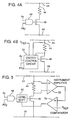
- FIGS. 4A and 4B are diagrams of possible drivers for use in the driver circuitry of FIG. 3.
- FIG. 5 is a schematic diagram of one embodiment of the energy control circuit shown in the driver design of FIG. 4B.
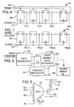
- FIG. 6 is a schematic diagram of one embodiment of the address generating device shown in FIG. 3.
- FIG. 7 is a schematic diagram of one embodiment of the print enable register shown in FIG. 3.
- FIG. 8 is a block diagram of another embodiment of the printhead driver circuitry that includes a pulse width modulation (PWM) converter.
- PWM pulse width modulation
- FIG. 9 is a schematic diagram of another embodiment of printhead driver circuitry that includes gray scale modulation.
- FIG. 10 is a schematic diagram of a multiplexing scheme for reducing the number of control interconnections between the printer and printhead.
- FIG. 1 shows printhead interface circuitry 10 with an inkjet printer 12 and an IDH inkjet printhead 14.
- Printing commands are transmitted from the interface circuitry 10, which is conventional in design, to driver circuitry on the printhead 14 through multiple interconnections 18.
- These interconnections 18 include primitive selects, primitive commons and control interconnections.
- the interconnections 18 are operably connected to the driver circuitry on the printhead 14 through various connecting pads for controlling the energizing of heater resistors.
- FIG. 2 illustrates a driver matrix (rectangular array) within driver circuitry 16 on the printhead 14 for selecting which drivers to fire in response to print commands from the printer. While the matrix will be described in terms of rows and columns, it should be understood that these terms are not meant to imply physical limitations on the arrangement of drivers within the matrix or on the printhead. Drivers may be arranged in any manner so long as they can be identified in the matrix by two enable signals within the print command. Each driver generally comprises a heater resistor (R D ) 20, a switching device 22, a primitive select 24, a primitive common 26 and a control interconnection 28 (parasitic resistances (R P ) are also shown). The switching device 22 is connected in series with the resistor 20 between the primitive select 24 and primitive common 26.
- R D heater resistor
- R P parsitic resistances
- the control interconnection 28 is also connected to the switching device 22 for switching the device 22 between a conductive state and a nonconductive state. In the conductive state, the device 22 completes a circuit from the primitive select 24 through the resistor 20 to the primitive common 26 to energize the heater resistor.
- Each row of drivers in the matrix is a primitive and may be selectively fired by powering the associated primitive select (“power") interconnection 24, such as PS1 for the top row shown in FIG. 2.
- power the associated primitive select
- the parasitic resistances R P of the primitive select and common interconnections are carefully balanced as shown and only one resistor 20 is energized at a time per primitive.
- any number of the primitive selects may be enabled concurrently.
- Each enabled primitive select 24 such as PS1, PS2, etc., thus delivers both power and one of the enable signals to the driver circuitry 16.
- the other enable signal for the driver matrix is an address signal provided by each control interconnection 28, such as A1, A2, etc., only one of which is preferably active at a time.
- Each control interconnection 28 is tied to all of the switching devices 22 in a matrix column so that all such switching devices are conductive when the interconnection is enabled or "active," i.e., at a voltage level which turns on the switching devices 22.
- a primitive select interconnection 24 and a control interconnection 28 for a heater resistor R D 20 are both active concurrently, that resistor 20 is energized.
- each matrix column could be a primitive or other defined group of drivers and each row could be a column or other defined group of drivers tied to a single control interconnection 28.
- “Matrix" as used herein refers to an electrical, not physical, relationship.
- the interconnections for controlling the printhead driver circuitry of FIG. 2 include separate primitive select and primitive common interconnections for each primitive and separate control interconnections for each matrix column.
- a typical driver matrix comprises an array of 8 primitives and 13 columns, requiring 29 interconnections. Increasing the number of drivers to 300 with a similar matrix would only increase the number of interconnections to 49.
- FIG. 3 shows an advanced embodiment of printhead driver circuitry 30 for minimizing the number of interconnections 24, 26 and 28.
- Primitive select interconnection 24 and common interconnection 26 provide constant power to an array 32 of drivers 31.
- "Array,” like matrix, as used herein refers to an electrical, not physical, relationship. At a minimum, one of each interconnections 24 and 26 is required for the entire array of drivers, assuming the parasitic resistances R P in the array 32 are balanced throughout. Because such balancing may be difficult to achieve in practice, it may be desirable to have the array 32 divided into primitives each with interconnections 24, 26 connected in the manner shown in FIG. 2. Alternatively, an energy control circuit may be incorporated into the driver circuitry 30, as will be discussed.
- Control interconnection 28 provides a print command from the printer interface circuitry 10 to the driver circuitry 30.
- the print command includes an address generating signal such as a clock signal and a print enable signal. These two signals may be carried on separate interconnections 28 or combined using known data compression techniques in a signal on a single interconnection, as will be described. Whichever way the two signals arrive at the printhead 14, they are directed to different components of circuitry 30 for selecting one or more drivers 31 from a driver array 32 have n-by-m drivers.
- One of these components is an address generator 34 which receives the print command and in response generates a address signals for the drivers 31 of array 32.
- the address generator 34 has an input for receiving the address generating signal and a plurality of address lines as outputs for transmitting address signals to the drivers of the array 32. Preferably only one of the address lines is active at one time, although it may be possible to have generator 34 produce concurrent address signals if desired.
- Each of these lines is interconnected to a row of drivers in the array 32 such that each driver in the row receives the address.
- the address generator 34 may be a state machine, circular shift register or other equivalent device that can receive an address generating signal and in response generate multiple address signals. FIG.
- FIG. 6 shows a shift register embodiment of such a generator 34 comprising a number of D flip flops 36 connected from output to input.
- the address generating signal in this example is a clock signal 37 within the print command which is applied to a clock input on each of the flip flops 36.
- the outputs of the generator 34, A(1), A(2),..., A(n) are active individually in sequential order.
- a reset input may also be provided for receiving an reset signal 38 from the printer.
- a reset of generator 34 to an initial state may be desired at power up of the printer or other appropriate times in the printing process.
- register 40 receives the print command and in response generates one or more print enable signals.
- the function of these print enable signals is analogous to the enabling function provided by primitive select interconnections 24, 26 in the embodiment of FIG. 2.
- register 40 converts a serial stream of print enable signals it receives from the printer 12 into a format for applying the print enable signals concurrently to one or more columns of drivers in array 32.
- FIG. 7 shows one embodiment of the register 40 in the form of a serial-to-parallel shift register comprising a row of connected D flip flops 42.
- the print command data is applied serially to the D input of the first flip flop and clocked through to the output of the mth flip flop, which corresponds to the mth column in the array 32.
- the outputs of the flip flops 42 are provided in parallel.
- a clock signal for clocking the D flip flops 42 may be the same clock signal that forms the address generating signal for address generator 34 or may be a separate signal.
- each driver 31 comprises a heater resistor 44, an associated switching device 46 such as a MOSFET in series with the resistor, and a logic gate 48 such as a two-input AND gate connected for controlling the switching device 46.
- the resistor 44 and switching device 46 are operably connected between a power interconnection 24 and a common interconnection 26.
- the inputs to the gate 48 are an address signal from the generator 34, such as signal Ax (where x indicates the xth row of the array 32), and a print enable signal PEy from register 40 (where y represents the yth column of the array 32).
- the switching device 46 is driven between conductive and nonconductive states by the presence or absence of these two signals at the logic gate 48. Thus in response to a print command from the printer 12 to fire a particular driver, the switching device 46 energizes the associated heater resistor 44 by allowing current to flow from the power interconnection 24 through the resistor to the common interconnection 26.
- the number of power interconnections 24, 26 may be reduced to a minimum if the firing energy per resistor can be equalized without the use of primitives in array 32. In the ideal case, the power interconnections could be reduced to one power interconnection 24 and one common interconnection 26. This arrangement would allow more than one driver to be fired per row in the array 32 of FIG. 3 if desired.
- FIG. 4B shows one example of such a mechanism in the form of an energy control circuit 50.
- the circuit 50 monitors the voltage across each heater resistor 44 and compares the monitored voltage to a reference voltage. The output of that comparison controls the strength of the drive signal applied to the gate of switching device 46 so that the switch is driven to conduct sufficiently to achieve the desired voltage across resistor 44.
- One form of circuit 50 is illustrated in FIG. 5.
- An instrument amplifier 52 measures the voltage drop across the resistor 44. The magnitude of this voltage is compared at a comparator 54 to a reference voltage REF that is the same reference voltage for each heater resistor 44 in the array 32.
- the output signal of the comparator 54 is applied to a level shift circuit 56 that shifts the level of voltage applied to the gate of switching device 46 in an appropriate direction.
- Circuit 50 and several equivalents are more fully shown and described in U.S. Patent No. 5,083,137, commonly owned by the present assignee and hereby incorporated by reference.
- FIG. 8 is a partial view of the embodiment in FIG. 3 in which a data converter 58 is placed between the interconnections from the printer 12 and the driver circuitry 30.
- the data converter 58 decodes an encoded electrical signal and, if the data has also been compressed, uncompresses the data as well.
- Any of a number of encoding schemes maybe used, including but not limited to pulse code modulation, pulse width modulation, run length limited encoding and time division multiplexing. By using such a scheme, the print command may be carried on a single interconnection or at least fewer interconnections than if no encoding is used.
- Data converter 58 of conventional design, converts the print command into the print enable signal and address generating signal (or address signal if address generation is not performed on the printhead).
- the intensity of the ink (multi-color or black) printed by the printer 12 is a function of ink drop volume and drop velocity. This intensity can be scaled by varying the control voltage applied to the gate of switching device 46 (or switching device 22 in FIG. 2.) This voltage controls the amount of energy delivered to the heater resistor by power interconnections 24 and 26, as described above.
- One approach for providing for such gray scale printing is shown in FIG. 9.
- a number of analog voltage levels GL1,...,GLn are generated by an on- or off-printhead voltage reference and are provided as signal inputs to a selection device such as a multiplexer 60 that connects to the input of each switching device 46.
- Ax is an address signal to an enable input of multiplexer 60. This scheme requires a group of m bits of print enable data for each row of drivers in array 32. A particular driver fires when its address signal and its PE.LVL bus are both active. The analog voltage GL selected depends upon the data on the PE.LVL print enable bus.
- an alternative approach to reducing the interconnections to the printhead 14 is multiplexing the control interconnections to the drivers in the circuitry 16 of FIG. 2.
- This approach is called “row sub-multiplexing” (RSM).
- RSM row sub-multiplexing
- RSM has advantages in simplicity and the small number of active devices, e.g., transistors, required for implementation.
- RSM also permits fabricating the required printhead circuitry using a simple NMOS process.
- the additional number of active devices required for RSM compared to the driver circuit 16 in FIG. 2 is equal to the number of rows in the matrix. Therefore RSM has only a negligible effect on the size of the driver circuit. In fact, depending on the specific layout of the driver circuit, RSM may actually reduce the circuit size because of the reduced number of interconnection pads.
- RTL resistor-transistor logic
- FIG. 10 shows a simple example of RSM.
- the multiplexer 70 is located on printhead 14 and comprises groups of X and Y inputs serially connected through resistors R b 71 and logic gates 72.
- a control line Ai is connected at one location to a node between each resistor R b and gate 72 and at another location to a switching device 22 within driver circuitry 16.
- Each input group has a single X input and multiple paths each through a resistor R b , gate and Y input as desired.
- the Y inputs are common to multiple groups.
- a control line Ai is enabled if the Xi input signal is enabled and the Yi input signal is disabled.
- control lines A1,..., Ai to the switching devices 22 are sequentially enabled one at a time.
- inputs X1 and Y2 are enabled and inputs X2 and Y1 are disabled.
- control lines A2,..., Ai are sequentially enabled.
- the power consumed by the row multiplexer 70 depends inversely on the resistance of resistors R b .
- the resistors must have enough resistance that the power consumed does not contribute to excessive printhead temperature, which can degrade print quality.
- the switching time for turning on the drivers 31 within driver circuitry 16 is proportional to the value of the resistors R b .
- the desire for low printhead temperature and fast switching time are thus in conflict.
- One way of reducing switching time, power consumption and temperature is to increase the number of X inputs and decrease the number of Y inputs. But this option increases both the number of interconnections and the number of active devices from the minimum set forth above.
- the embodiment can be modified without departing from such principles.
- the address signals may come directly from the printer over interconnections rather than being generated within driver circuitry 30, if desired.
- Components such as logic gates 48 and switching devices 46 may be interchanged with analog or software-based equivalent structure such as look up tables, comparison operations, etc. Therefore, the illustrated embodiments should be considered as an examples only of our preferred forms of the invention and not as limitations on the scope of the invention. We claim as the invention all embodiments of the invention that come within the scope and spirit of the following claims.
Landscapes
- Physics & Mathematics (AREA)
- Engineering & Computer Science (AREA)
- Mathematical Physics (AREA)
- General Engineering & Computer Science (AREA)
- General Physics & Mathematics (AREA)
- Theoretical Computer Science (AREA)
- Particle Formation And Scattering Control In Inkjet Printers (AREA)
- Ink Jet (AREA)
- Accessory Devices And Overall Control Thereof (AREA)
Applications Claiming Priority (2)
| Application Number | Priority Date | Filing Date | Title |
|---|---|---|---|
| US95883392A | 1992-10-08 | 1992-10-08 | |
| US958833 | 1992-10-08 |
Related Child Applications (1)
| Application Number | Title | Priority Date | Filing Date |
|---|---|---|---|
| EP03078307 Division | 2003-10-20 |
Publications (2)
| Publication Number | Publication Date |
|---|---|
| EP0592221A1 true EP0592221A1 (de) | 1994-04-13 |
| EP0592221B1 EP0592221B1 (de) | 2005-02-16 |
Family
ID=25501368
Family Applications (1)
| Application Number | Title | Priority Date | Filing Date |
|---|---|---|---|
| EP93307989A Expired - Lifetime EP0592221B1 (de) | 1992-10-08 | 1993-10-07 | Druckkopf mit verminderten Verbindungen zu einem Drucker |
Country Status (5)
| Country | Link |
|---|---|
| US (1) | US5541629A (de) |
| EP (1) | EP0592221B1 (de) |
| JP (1) | JPH06198869A (de) |
| DE (1) | DE69333758T2 (de) |
| SG (1) | SG47435A1 (de) |
Cited By (18)
| Publication number | Priority date | Publication date | Assignee | Title |
|---|---|---|---|---|
| EP0677388A2 (de) * | 1994-04-14 | 1995-10-18 | Hewlett-Packard Company | Tintenstrahldruckkopf mit Adressen- und Databus |
| WO1996032270A1 (en) * | 1995-04-12 | 1996-10-17 | Eastman Kodak Company | Integrated drive circuitry in drop on demand print heads |
| EP0705695A3 (de) * | 1994-10-06 | 1997-01-22 | Hewlett Packard Co | Tintenzuführsystem |
| EP0822073A2 (de) * | 1996-07-31 | 1998-02-04 | Canon Kabushiki Kaisha | Druckkopf, Kopfkartusche und Drucker mit dem Druckkopf |
| EP0822072A2 (de) * | 1996-07-31 | 1998-02-04 | Canon Kabushiki Kaisha | Aufzeichnungskopf und Aufzeichnungsverfahren |
| WO2001003932A1 (en) * | 1999-07-12 | 2001-01-18 | Olivetti Lexikon S.P.A. | Integrated printhead |
| EP1072412A3 (de) * | 1999-07-30 | 2001-08-29 | Hewlett-Packard Company, A Delaware Corporation | Auf einem dynamischen Speicher basierende Aktivierungszelle für einen thermischen Tintenstrahldruckkopf |
| EP1212197A1 (de) * | 1999-08-05 | 2002-06-12 | Lexmark International, Inc. | Übertragungsadressierung von heizelementen für den tintenstrahldruck |
| EP1359013A1 (de) * | 2002-04-29 | 2003-11-05 | Hewlett-Packard Company | Ausstosspulsen in einem Flüssigkeitsausstossgerät |
| US6659581B2 (en) | 2001-01-05 | 2003-12-09 | Hewlett-Packard Development Company, L.P. | Integrated programmable fire pulse generator for inkjet printhead assembly |
| US6932460B2 (en) | 1999-07-30 | 2005-08-23 | Hewlett-Packard Development Company, L.P. | Fluid ejection device |
| US7029084B2 (en) | 2001-01-05 | 2006-04-18 | Hewlett-Packard Development Company, L.P. | Integrated programmable fire pulse generator for inkjet printhead assembly |
| WO2007065191A1 (en) * | 2005-12-05 | 2007-06-14 | Silverbrook Research Pty Ltd | Printhead cartridge interface having power regulation |
| US7461922B2 (en) | 2005-12-05 | 2008-12-09 | Silverbrook Research Pty Ltd | Printing system having power regulating printhead cartridge interface |
| US7461910B2 (en) | 2005-12-05 | 2008-12-09 | Silverbrook Research Pty Ltd | Printing system having power storage printhead cartridge interface |
| US7465020B2 (en) | 2005-12-05 | 2008-12-16 | Silverbrook Research Pty Ltd | Printhead cartridge interface having power storage |
| US7467853B2 (en) | 2005-12-05 | 2008-12-23 | Silverbrook Research Pty Ltd | Cradle for printhead cartridge having power regulation interface |
| US7722185B2 (en) | 2005-12-05 | 2010-05-25 | Silverbrook Research Pty Ltd | Cradle for printhead cartridge having power storage interface |
Families Citing this family (71)
| Publication number | Priority date | Publication date | Assignee | Title |
|---|---|---|---|---|
| US6310639B1 (en) | 1996-02-07 | 2001-10-30 | Hewlett-Packard Co. | Printer printhead |
| US6259463B1 (en) | 1997-10-30 | 2001-07-10 | Hewlett-Packard Company | Multi-drop merge on media printing system |
| US6193347B1 (en) | 1997-02-06 | 2001-02-27 | Hewlett-Packard Company | Hybrid multi-drop/multi-pass printing system |
| US5969745A (en) * | 1997-07-12 | 1999-10-19 | Lucent Technologies Inc | Gray shade driver for pixel array |
| US6386674B1 (en) | 1997-10-28 | 2002-05-14 | Hewlett-Packard Company | Independent power supplies for color inkjet printers |
| US6290333B1 (en) | 1997-10-28 | 2001-09-18 | Hewlett-Packard Company | Multiple power interconnect arrangement for inkjet printhead |
| US6193345B1 (en) | 1997-10-30 | 2001-02-27 | Hewlett-Packard Company | Apparatus for generating high frequency ink ejection and ink chamber refill |
| US6234613B1 (en) | 1997-10-30 | 2001-05-22 | Hewlett-Packard Company | Apparatus for generating small volume, high velocity ink droplets in an inkjet printer |
| US6428145B1 (en) | 1998-12-17 | 2002-08-06 | Hewlett-Packard Company | Wide-array inkjet printhead assembly with internal electrical routing system |
| US6755495B2 (en) * | 2001-03-15 | 2004-06-29 | Hewlett-Packard Development Company, L.P. | Integrated control of power delivery to firing resistors for printhead assembly |
| US6729707B2 (en) * | 2002-04-30 | 2004-05-04 | Hewlett-Packard Development Company, L.P. | Self-calibration of power delivery control to firing resistors |
| US6309052B1 (en) | 1999-04-30 | 2001-10-30 | Hewlett-Packard Company | High thermal efficiency ink jet printhead |
| US6139131A (en) | 1999-08-30 | 2000-10-31 | Hewlett-Packard Company | High drop generator density printhead |
| US6280019B1 (en) | 1999-08-30 | 2001-08-28 | Hewlett-Packard Company | Segmented resistor inkjet drop generator with current crowding reduction |
| US7019866B1 (en) | 1999-08-30 | 2006-03-28 | Hewlett-Packard Development Company, L.P. | Common communication bus and protocol for multiple injet printheads in a printing system |
| US6318846B1 (en) | 1999-08-30 | 2001-11-20 | Hewlett-Packard Company | Redundant input signal paths for an inkjet print head |
| US6190000B1 (en) * | 1999-08-30 | 2001-02-20 | Hewlett-Packard Company | Method and apparatus for masking address out failures |
| US6234598B1 (en) | 1999-08-30 | 2001-05-22 | Hewlett-Packard Company | Shared multiple terminal ground returns for an inkjet printhead |
| US6491377B1 (en) | 1999-08-30 | 2002-12-10 | Hewlett-Packard Company | High print quality printhead |
| US6312079B1 (en) | 1999-09-22 | 2001-11-06 | Lexmark International, Inc. | Print head drive scheme for serial compression of I/O in ink jets |
| KR20010028853A (ko) * | 1999-09-27 | 2001-04-06 | 윤종용 | 잉크젯 프린터 헤드 |
| US6302507B1 (en) * | 1999-10-13 | 2001-10-16 | Hewlett-Packard Company | Method for controlling the over-energy applied to an inkjet print cartridge using dynamic pulse width adjustment based on printhead temperature |
| US6439678B1 (en) * | 1999-11-23 | 2002-08-27 | Hewlett-Packard Company | Method and apparatus for non-saturated switching for firing energy control in an inkjet printer |
| TW514596B (en) | 2000-02-28 | 2002-12-21 | Hewlett Packard Co | Glass-fiber thermal inkjet print head |
| US6398346B1 (en) | 2000-03-29 | 2002-06-04 | Lexmark International, Inc. | Dual-configurable print head addressing |
| US6431677B1 (en) | 2000-06-08 | 2002-08-13 | Lexmark International, Inc | Print head drive scheme |
| TW479022B (en) * | 2000-08-29 | 2002-03-11 | Acer Peripherals Inc | Drive circuit of ink-jet head with temperature detection function |
| US6481817B1 (en) | 2000-10-30 | 2002-11-19 | Hewlett-Packard Company | Method and apparatus for ejecting ink |
| US6402279B1 (en) | 2000-10-30 | 2002-06-11 | Hewlett-Packard Company | Inkjet printhead and method for the same |
| US6582042B1 (en) | 2000-10-30 | 2003-06-24 | Hewlett-Packard Development Company, L.P. | Method and apparatus for transferring information to a printhead |
| US6726298B2 (en) | 2001-02-08 | 2004-04-27 | Hewlett-Packard Development Company, L.P. | Low voltage differential signaling communication in inkjet printhead assembly |
| US6557976B2 (en) | 2001-02-14 | 2003-05-06 | Hewlett-Packard Development Company, L.P. | Electrical circuit for wide-array inkjet printhead assembly |
| US6755503B2 (en) | 2001-02-23 | 2004-06-29 | Mailroom Technology, Inc. | Housekeeping station |
| US6478396B1 (en) | 2001-03-02 | 2002-11-12 | Hewlett-Packard Company | Programmable nozzle firing order for printhead assembly |
| US6471320B2 (en) | 2001-03-09 | 2002-10-29 | Hewlett-Packard Company | Data bandwidth reduction to printhead with redundant nozzles |
| US6394580B1 (en) | 2001-03-20 | 2002-05-28 | Hewlett-Packard Company | Electrical interconnection for wide-array inkjet printhead assembly |
| US6460974B1 (en) | 2001-07-27 | 2002-10-08 | Hewlett-Packard Company | Micro-pump and method for generating fluid flow |
| US6932453B2 (en) | 2001-10-31 | 2005-08-23 | Hewlett-Packard Development Company, L.P. | Inkjet printhead assembly having very high drop rate generation |
| US6746107B2 (en) | 2001-10-31 | 2004-06-08 | Hewlett-Packard Development Company, L.P. | Inkjet printhead having ink feed channels defined by thin-film structure and orifice layer |
| US6543879B1 (en) | 2001-10-31 | 2003-04-08 | Hewlett-Packard Company | Inkjet printhead assembly having very high nozzle packing density |
| US6800497B2 (en) | 2002-04-30 | 2004-10-05 | Hewlett-Packard Development Company, L.P. | Power switching transistor and method of manufacture for a fluid ejection device |
| US6720223B2 (en) | 2002-04-30 | 2004-04-13 | Hewlett-Packard Development Company, L.P. | Power |
| US6712439B1 (en) | 2002-12-17 | 2004-03-30 | Lexmark International, Inc. | Integrated circuit and drive scheme for an inkjet printhead |
| US6962399B2 (en) * | 2002-12-30 | 2005-11-08 | Lexmark International, Inc. | Method of warning a user of end of life of a consumable for an ink jet printer |
| US6736488B1 (en) | 2003-05-23 | 2004-05-18 | Hewlett-Packard Development Company, L.P. | Electrical interconnect for printhead assembly |
| FR2861814B1 (fr) * | 2003-11-04 | 2006-02-03 | Cit Alcatel | Dispositif de pompage par micropompes a transpiration thermique |
| US20050174376A1 (en) * | 2004-02-09 | 2005-08-11 | Deshmukh Sudhir G. | Device for monitoring dispensing of dispensable compositions |
| US20050174371A1 (en) * | 2004-02-09 | 2005-08-11 | Deshmukh Sudhir G. | Process for monitoring dispensing of dispensable compositions |
| US7175248B2 (en) * | 2004-02-27 | 2007-02-13 | Hewlett-Packard Development Company, L.P. | Fluid ejection device with feedback circuit |
| US7240981B2 (en) * | 2004-02-27 | 2007-07-10 | Hewlett-Packard Development Company, L.P. | Wide array fluid ejection device |
| US7497536B2 (en) | 2004-04-19 | 2009-03-03 | Hewlett-Packard Development Company, L.P. | Fluid ejection device |
| US7384113B2 (en) * | 2004-04-19 | 2008-06-10 | Hewlett-Packard Development Company, L.P. | Fluid ejection device with address generator |
| US7722144B2 (en) * | 2004-04-19 | 2010-05-25 | Hewlett-Packard Development Company, L.P. | Fluid ejection device |
| US20050237354A1 (en) * | 2004-04-25 | 2005-10-27 | Quintana Jason M | Selection of printheads via enable lines |
| WO2006017800A2 (en) * | 2004-08-06 | 2006-02-16 | Secocmbe S Dana | Means for higher speed inkjet printing |
| US7661782B2 (en) * | 2007-04-19 | 2010-02-16 | Lexmark International, Inc. | Current control circuit for micro-fluid ejection device heaters |
| US7871142B2 (en) * | 2007-08-17 | 2011-01-18 | Hewlett-Packard Development Company, L.P. | Systems and methods for controlling ink jet pens |
| JP2010181255A (ja) * | 2009-02-05 | 2010-08-19 | Omron Corp | 断線検出装置、制御装置および電力調整器 |
| US8313163B2 (en) | 2010-05-04 | 2012-11-20 | Xerox Corporation | Method and system to compensate for process direction misalignment of printheads in a continuous web inkjet printer |
| US8882237B2 (en) * | 2011-01-25 | 2014-11-11 | Hewlett-Packard Development Company, L.P. | Printhead apparatus, printer system and method of printhead built-in test |
| RU2502605C2 (ru) * | 2011-10-18 | 2013-12-27 | Российская Федерация, от имени которой выступает Министерство промышленности и торговли Российской Федерации (Минпромторг России) | Многослойный материал для спасательных средств |
| US9272301B2 (en) | 2013-03-01 | 2016-03-01 | S. Dana Seccombe | Apparatus and method for non-contact manipulation, conditioning, shaping and drying of surfaces |
| US9833991B2 (en) * | 2014-09-29 | 2017-12-05 | Funai Electric Co., Ltd. | Printhead and an inkjet printer |
| US10160203B2 (en) | 2014-10-29 | 2018-12-25 | Hewlett-Packard Development Company, L.P. | Printhead fire signal control |
| WO2019240760A1 (en) | 2018-06-11 | 2019-12-19 | Hewlett-Packard Development Company, L.P. | Thermal zone selection with a circular shift register |
| US11485134B2 (en) | 2019-02-06 | 2022-11-01 | Hewlett-Packard Development Company, L.P. | Data packets comprising random numbers for controlling fluid dispensing devices |
| US11676645B2 (en) | 2019-02-06 | 2023-06-13 | Hewlett-Packard Development Company, L.P. | Communicating print component |
| PL3717257T3 (pl) | 2019-02-06 | 2021-12-06 | Hewlett-Packard Development Company, L.P. | Komunikujący się komponent drukujący |
| AU2019428638B2 (en) * | 2019-02-06 | 2023-11-09 | Hewlett-Packard Development Company, L.P. | Integrated circuit with address drivers for fluidic die |
| US11407218B2 (en) | 2019-02-06 | 2022-08-09 | Hewlett-Packard Development Company, L.P. | Identifying random bits in control data packets |
| MX2021009121A (es) | 2019-02-06 | 2021-09-08 | Hewlett Packard Development Co | Componente de impresion con conjunto de memoria usando se?al intermitente de reloj. |
Citations (3)
| Publication number | Priority date | Publication date | Assignee | Title |
|---|---|---|---|---|
| EP0405574A2 (de) * | 1989-06-30 | 1991-01-02 | Canon Kabushiki Kaisha | Aufzeichnungskopf |
| US5006864A (en) * | 1979-04-02 | 1991-04-09 | Canon Kabushiki Kaisha | Information read-out and recording apparatus |
| EP0461938A2 (de) * | 1990-06-15 | 1991-12-18 | Canon Kabushiki Kaisha | Tintenstrahlaufzeichnungsverfahren und zugehöriges Tintenstrahlaufzeichnungsgerät |
Family Cites Families (12)
| Publication number | Priority date | Publication date | Assignee | Title |
|---|---|---|---|---|
| US3852563A (en) * | 1974-02-01 | 1974-12-03 | Hewlett Packard Co | Thermal printing head |
| US4317124A (en) * | 1979-02-14 | 1982-02-23 | Canon Kabushiki Kaisha | Ink jet recording apparatus |
| US4345262A (en) * | 1979-02-19 | 1982-08-17 | Canon Kabushiki Kaisha | Ink jet recording method |
| US4719477A (en) * | 1986-01-17 | 1988-01-12 | Hewlett-Packard Company | Integrated thermal ink jet printhead and method of manufacture |
| JP2656481B2 (ja) * | 1987-02-13 | 1997-09-24 | キヤノン株式会社 | インクジエツト記録ヘツド |
| US4947192A (en) * | 1988-03-07 | 1990-08-07 | Xerox Corporation | Monolithic silicon integrated circuit chip for a thermal ink jet printer |
| US4887098A (en) * | 1988-11-25 | 1989-12-12 | Xerox Corporation | Thermal ink jet printer having printhead transducers with multilevelinterconnections |
| US5144336A (en) * | 1990-01-23 | 1992-09-01 | Hewlett-Packard Company | Method and apparatus for controlling the temperature of thermal ink jet and thermal printheads that have a heating matrix system |
| US5053790A (en) * | 1990-07-02 | 1991-10-01 | Eastman Kodak Company | Parasitic resistance compensation for thermal printers |
| US5187500A (en) * | 1990-09-05 | 1993-02-16 | Hewlett-Packard Company | Control of energy to thermal inkjet heating elements |
| US5083137A (en) * | 1991-02-08 | 1992-01-21 | Hewlett-Packard Company | Energy control circuit for a thermal ink-jet printhead |
| US5223853A (en) * | 1992-02-24 | 1993-06-29 | Xerox Corporation | Electronic spot size control in a thermal ink jet printer |
-
1993
- 1993-10-07 DE DE69333758T patent/DE69333758T2/de not_active Expired - Lifetime
- 1993-10-07 EP EP93307989A patent/EP0592221B1/de not_active Expired - Lifetime
- 1993-10-07 SG SG1996001355A patent/SG47435A1/en unknown
- 1993-10-08 JP JP5252726A patent/JPH06198869A/ja active Pending
-
1994
- 1994-09-26 US US08/312,489 patent/US5541629A/en not_active Expired - Lifetime
Patent Citations (3)
| Publication number | Priority date | Publication date | Assignee | Title |
|---|---|---|---|---|
| US5006864A (en) * | 1979-04-02 | 1991-04-09 | Canon Kabushiki Kaisha | Information read-out and recording apparatus |
| EP0405574A2 (de) * | 1989-06-30 | 1991-01-02 | Canon Kabushiki Kaisha | Aufzeichnungskopf |
| EP0461938A2 (de) * | 1990-06-15 | 1991-12-18 | Canon Kabushiki Kaisha | Tintenstrahlaufzeichnungsverfahren und zugehöriges Tintenstrahlaufzeichnungsgerät |
Cited By (38)
| Publication number | Priority date | Publication date | Assignee | Title |
|---|---|---|---|---|
| US5600354A (en) * | 1992-04-02 | 1997-02-04 | Hewlett-Packard Company | Wrap-around flex with address and data bus |
| US5638101A (en) * | 1992-04-02 | 1997-06-10 | Hewlett-Packard Company | High density nozzle array for inkjet printhead |
| EP0677388A2 (de) * | 1994-04-14 | 1995-10-18 | Hewlett-Packard Company | Tintenstrahldruckkopf mit Adressen- und Databus |
| EP0677388A3 (de) * | 1994-04-14 | 1996-01-17 | Hewlett Packard Co | Tintenstrahldruckkopf mit Adressen- und Databus. |
| EP0705695A3 (de) * | 1994-10-06 | 1997-01-22 | Hewlett Packard Co | Tintenzuführsystem |
| WO1996032270A1 (en) * | 1995-04-12 | 1996-10-17 | Eastman Kodak Company | Integrated drive circuitry in drop on demand print heads |
| EP0822073A2 (de) * | 1996-07-31 | 1998-02-04 | Canon Kabushiki Kaisha | Druckkopf, Kopfkartusche und Drucker mit dem Druckkopf |
| EP0822072A2 (de) * | 1996-07-31 | 1998-02-04 | Canon Kabushiki Kaisha | Aufzeichnungskopf und Aufzeichnungsverfahren |
| EP0822072A3 (de) * | 1996-07-31 | 1998-12-30 | Canon Kabushiki Kaisha | Aufzeichnungskopf und Aufzeichnungsverfahren |
| EP0822073A3 (de) * | 1996-07-31 | 1999-01-20 | Canon Kabushiki Kaisha | Druckkopf, Kopfkartusche und Drucker mit dem Druckkopf |
| US6130692A (en) * | 1996-07-31 | 2000-10-10 | Canon Kabushiki Kaisha | Printhead operating by time divisional driving of blocks of printing elements, and head cartridge and printer using such a printhead |
| US6382756B1 (en) | 1996-07-31 | 2002-05-07 | Canon Kabushiki Kaisha | Recording head and recording method |
| WO2001003932A1 (en) * | 1999-07-12 | 2001-01-18 | Olivetti Lexikon S.P.A. | Integrated printhead |
| US6565175B1 (en) | 1999-07-12 | 2003-05-20 | Olivetti Tecnost S.P.A. | Integrated printhead |
| US6543882B2 (en) | 1999-07-30 | 2003-04-08 | Hewlett-Packard Company | Dynamic memory based firing cell for thermal ink jet printhead |
| KR100779342B1 (ko) * | 1999-07-30 | 2007-11-23 | 휴렛-팩커드 컴퍼니(델라웨어주법인) | 집적 회로 분사 셀, 분사 어레이 및 잉크젯 분사 시스템 |
| US6540333B2 (en) | 1999-07-30 | 2003-04-01 | Hewlett-Packard Development Company, L.P. | Dynamic memory based firing cell for thermal ink jet printhead |
| EP1072412A3 (de) * | 1999-07-30 | 2001-08-29 | Hewlett-Packard Company, A Delaware Corporation | Auf einem dynamischen Speicher basierende Aktivierungszelle für einen thermischen Tintenstrahldruckkopf |
| US6932460B2 (en) | 1999-07-30 | 2005-08-23 | Hewlett-Packard Development Company, L.P. | Fluid ejection device |
| US6439697B1 (en) | 1999-07-30 | 2002-08-27 | Hewlett-Packard Company | Dynamic memory based firing cell of thermal ink jet printhead |
| EP1212197A4 (de) * | 1999-08-05 | 2002-10-16 | Lexmark Int Inc | Übertragungsadressierung von heizelementen für den tintenstrahldruck |
| EP1212197A1 (de) * | 1999-08-05 | 2002-06-12 | Lexmark International, Inc. | Übertragungsadressierung von heizelementen für den tintenstrahldruck |
| US6659581B2 (en) | 2001-01-05 | 2003-12-09 | Hewlett-Packard Development Company, L.P. | Integrated programmable fire pulse generator for inkjet printhead assembly |
| US7029084B2 (en) | 2001-01-05 | 2006-04-18 | Hewlett-Packard Development Company, L.P. | Integrated programmable fire pulse generator for inkjet printhead assembly |
| EP1359013A1 (de) * | 2002-04-29 | 2003-11-05 | Hewlett-Packard Company | Ausstosspulsen in einem Flüssigkeitsausstossgerät |
| US7104624B2 (en) | 2002-04-29 | 2006-09-12 | Hewlett-Packard Development Company, L.P. | Fire pulses in a fluid ejection device |
| WO2007065191A1 (en) * | 2005-12-05 | 2007-06-14 | Silverbrook Research Pty Ltd | Printhead cartridge interface having power regulation |
| US7461922B2 (en) | 2005-12-05 | 2008-12-09 | Silverbrook Research Pty Ltd | Printing system having power regulating printhead cartridge interface |
| US7461910B2 (en) | 2005-12-05 | 2008-12-09 | Silverbrook Research Pty Ltd | Printing system having power storage printhead cartridge interface |
| US7465020B2 (en) | 2005-12-05 | 2008-12-16 | Silverbrook Research Pty Ltd | Printhead cartridge interface having power storage |
| US7467853B2 (en) | 2005-12-05 | 2008-12-23 | Silverbrook Research Pty Ltd | Cradle for printhead cartridge having power regulation interface |
| US7722185B2 (en) | 2005-12-05 | 2010-05-25 | Silverbrook Research Pty Ltd | Cradle for printhead cartridge having power storage interface |
| US7824011B2 (en) | 2005-12-05 | 2010-11-02 | Silverbrook Research Pty Ltd | Cradle unit having pivoted connections for printhead cartridge |
| CN101326062B (zh) * | 2005-12-05 | 2011-04-13 | 西尔弗布鲁克研究有限公司 | 具有功率调节件的打印头墨盒接合件 |
| US7942496B2 (en) | 2005-12-05 | 2011-05-17 | Silverbrook Research Pty Ltd | Cradle unit for a printer assembly |
| US8025364B2 (en) | 2005-12-05 | 2011-09-27 | Silverbrook Research Pty Ltd | System for pivoted connection of cradle unit and printhead cartridge |
| US8091973B2 (en) | 2005-12-05 | 2012-01-10 | Silverbrook Research Pty Ltd | Printing system with power regulation |
| US8360555B2 (en) | 2005-12-05 | 2013-01-29 | Zamtec Ltd | Cradle unit for printhead cartridge having movable connectors |
Also Published As
| Publication number | Publication date |
|---|---|
| JPH06198869A (ja) | 1994-07-19 |
| DE69333758D1 (de) | 2005-03-24 |
| US5541629A (en) | 1996-07-30 |
| SG47435A1 (en) | 1998-04-17 |
| DE69333758T2 (de) | 2006-04-13 |
| EP0592221B1 (de) | 2005-02-16 |
Similar Documents
| Publication | Publication Date | Title |
|---|---|---|
| US5541629A (en) | Printhead with reduced interconnections to a printer | |
| KR100388181B1 (ko) | 프린트헤드, 프린트헤드 구동 방법 및 데이타 출력 장치 | |
| US5600354A (en) | Wrap-around flex with address and data bus | |
| EP1054772B1 (de) | Schaltung zur speichererweiterung für tintenstrahldruckkopf-identifizierungsschaltung | |
| AU706655B2 (en) | Ink jet print head identification circuit with serial out, dynamic shift registers | |
| US8177333B2 (en) | Element board for printhead, and printhead having the same | |
| JPH07169609A (ja) | 受動多重化抵抗器アレイ | |
| US7896469B2 (en) | Head substrate, printhead, head cartridge, and printing apparatus | |
| US5134425A (en) | Ohmic heating matrix | |
| EP0635374B1 (de) | Einrichtung und Verfahren zum Steuern von Thermodruckheizelementen in einer Aufzeichnungsvorrichtung | |
| EP0703086B1 (de) | Druckgerät und -verfahren mit logischem Stromkreis um die Eingangsrate von Videodaten zu reduzieren | |
| KR100438705B1 (ko) | 잉크 카트리지의 최대 구동전류를 감소시킬 수 있는잉크-젯 프린터 및 그 방법 | |
| US6712439B1 (en) | Integrated circuit and drive scheme for an inkjet printhead | |
| US20190030915A1 (en) | Thermal head control apparatus, tape printing apparatus comprising the same, and thermal head control head | |
| US7370921B2 (en) | Recording apparatus | |
| JP5031455B2 (ja) | 記録ヘッド用素子基板、記録ヘッド及び該記録ヘッドを用いた記録装置 | |
| US7828401B2 (en) | Recording apparatus | |
| JP2772170B2 (ja) | サーマルヘッド駆動回路及び印字装置 | |
| JPH11263034A (ja) | プリンタの熱要素のイネ―ブル群の大きさ及び動作を決定する方法及び装置 | |
| KR980000943A (ko) | 잉크젯 프린터의 다중 헤드 구동 장치 및 방법 | |
| JP2004001538A (ja) | 駆動用ic及び光プリントヘッド | |
| JP2000218854A (ja) | 駆動用ic及び光プリントヘッド | |
| KR20020056417A (ko) | 잉크젯프린터의 헤드 노즐 구동 방법 및 그 장치 | |
| KR19990020083A (ko) | 카트리지 캐리어에 매트릭스 방식의 헤드 드라이버를 장착한 잉크젯 프린터 | |
| JPH04303665A (ja) | サーマルプリンタ |
Legal Events
| Date | Code | Title | Description |
|---|---|---|---|
| PUAI | Public reference made under article 153(3) epc to a published international application that has entered the european phase |
Free format text: ORIGINAL CODE: 0009012 |
|
| AK | Designated contracting states |
Kind code of ref document: A1 Designated state(s): DE FR GB IT |
|
| RIN1 | Information on inventor provided before grant (corrected) |
Inventor name: SECCOMBE, DANA S. Inventor name: HULINGS, JAMES R. Inventor name: BADYAL, RAJEEV Inventor name: GARCIA, ANDRE Inventor name: SAUNDERS, MICHAEL B. |
|
| 17P | Request for examination filed |
Effective date: 19940929 |
|
| 17Q | First examination report despatched |
Effective date: 19970417 |
|
| APAB | Appeal dossier modified |
Free format text: ORIGINAL CODE: EPIDOS NOAPE |
|
| APAB | Appeal dossier modified |
Free format text: ORIGINAL CODE: EPIDOS NOAPE |
|
| APAD | Appeal reference recorded |
Free format text: ORIGINAL CODE: EPIDOS REFNE |
|
| RAP1 | Party data changed (applicant data changed or rights of an application transferred) |
Owner name: HEWLETT-PACKARD COMPANY, A DELAWARE CORPORATION |
|
| APBT | Appeal procedure closed |
Free format text: ORIGINAL CODE: EPIDOSNNOA9E |
|
| GRAP | Despatch of communication of intention to grant a patent |
Free format text: ORIGINAL CODE: EPIDOSNIGR1 |
|
| GRAS | Grant fee paid |
Free format text: ORIGINAL CODE: EPIDOSNIGR3 |
|
| GRAA | (expected) grant |
Free format text: ORIGINAL CODE: 0009210 |
|
| AK | Designated contracting states |
Kind code of ref document: B1 Designated state(s): DE FR GB IT |
|
| REG | Reference to a national code |
Ref country code: GB Ref legal event code: FG4D |
|
| REF | Corresponds to: |
Ref document number: 69333758 Country of ref document: DE Date of ref document: 20050324 Kind code of ref document: P |
|
| APAH | Appeal reference modified |
Free format text: ORIGINAL CODE: EPIDOSCREFNO |
|
| PLBE | No opposition filed within time limit |
Free format text: ORIGINAL CODE: 0009261 |
|
| STAA | Information on the status of an ep patent application or granted ep patent |
Free format text: STATUS: NO OPPOSITION FILED WITHIN TIME LIMIT |
|
| ET | Fr: translation filed | ||
| 26N | No opposition filed |
Effective date: 20051117 |
|
| REG | Reference to a national code |
Ref country code: GB Ref legal event code: 732E Free format text: REGISTERED BETWEEN 20120329 AND 20120404 |
|
| PGFP | Annual fee paid to national office [announced via postgrant information from national office to epo] |
Ref country code: FR Payment date: 20121107 Year of fee payment: 20 Ref country code: DE Payment date: 20121029 Year of fee payment: 20 |
|
| PGFP | Annual fee paid to national office [announced via postgrant information from national office to epo] |
Ref country code: GB Payment date: 20121025 Year of fee payment: 20 Ref country code: IT Payment date: 20121024 Year of fee payment: 20 |
|
| REG | Reference to a national code |
Ref country code: DE Ref legal event code: R071 Ref document number: 69333758 Country of ref document: DE |
|
| REG | Reference to a national code |
Ref country code: GB Ref legal event code: PE20 Expiry date: 20131006 |
|
| PG25 | Lapsed in a contracting state [announced via postgrant information from national office to epo] |
Ref country code: GB Free format text: LAPSE BECAUSE OF EXPIRATION OF PROTECTION Effective date: 20131006 Ref country code: DE Free format text: LAPSE BECAUSE OF EXPIRATION OF PROTECTION Effective date: 20131008 |