EP0591257B1 - Apparatus for temperature detection - Google Patents
Apparatus for temperature detection Download PDFInfo
- Publication number
- EP0591257B1 EP0591257B1 EP92911480A EP92911480A EP0591257B1 EP 0591257 B1 EP0591257 B1 EP 0591257B1 EP 92911480 A EP92911480 A EP 92911480A EP 92911480 A EP92911480 A EP 92911480A EP 0591257 B1 EP0591257 B1 EP 0591257B1
- Authority
- EP
- European Patent Office
- Prior art keywords
- detectors
- radiation
- detecting means
- area
- infra
- Prior art date
- Legal status (The legal status is an assumption and is not a legal conclusion. Google has not performed a legal analysis and makes no representation as to the accuracy of the status listed.)
- Expired - Lifetime
Links
Images
Classifications
-
- G—PHYSICS
- G01—MEASURING; TESTING
- G01J—MEASUREMENT OF INTENSITY, VELOCITY, SPECTRAL CONTENT, POLARISATION, PHASE OR PULSE CHARACTERISTICS OF INFRARED, VISIBLE OR ULTRAVIOLET LIGHT; COLORIMETRY; RADIATION PYROMETRY
- G01J5/00—Radiation pyrometry, e.g. infrared or optical thermometry
- G01J5/02—Constructional details
- G01J5/08—Optical arrangements
- G01J5/0801—Means for wavelength selection or discrimination
-
- G—PHYSICS
- G01—MEASURING; TESTING
- G01J—MEASUREMENT OF INTENSITY, VELOCITY, SPECTRAL CONTENT, POLARISATION, PHASE OR PULSE CHARACTERISTICS OF INFRARED, VISIBLE OR ULTRAVIOLET LIGHT; COLORIMETRY; RADIATION PYROMETRY
- G01J5/00—Radiation pyrometry, e.g. infrared or optical thermometry
- G01J5/0022—Radiation pyrometry, e.g. infrared or optical thermometry for sensing the radiation of moving bodies
-
- G—PHYSICS
- G01—MEASURING; TESTING
- G01J—MEASUREMENT OF INTENSITY, VELOCITY, SPECTRAL CONTENT, POLARISATION, PHASE OR PULSE CHARACTERISTICS OF INFRARED, VISIBLE OR ULTRAVIOLET LIGHT; COLORIMETRY; RADIATION PYROMETRY
- G01J5/00—Radiation pyrometry, e.g. infrared or optical thermometry
- G01J5/02—Constructional details
- G01J5/08—Optical arrangements
- G01J5/0818—Waveguides
- G01J5/0821—Optical fibres
-
- G—PHYSICS
- G01—MEASURING; TESTING
- G01J—MEASUREMENT OF INTENSITY, VELOCITY, SPECTRAL CONTENT, POLARISATION, PHASE OR PULSE CHARACTERISTICS OF INFRARED, VISIBLE OR ULTRAVIOLET LIGHT; COLORIMETRY; RADIATION PYROMETRY
- G01J5/00—Radiation pyrometry, e.g. infrared or optical thermometry
- G01J5/60—Radiation pyrometry, e.g. infrared or optical thermometry using determination of colour temperature
- G01J5/602—Radiation pyrometry, e.g. infrared or optical thermometry using determination of colour temperature using selective, monochromatic or bandpass filtering
Definitions
- This invention is concerned with apparatus for temperature detection and, in particular, with apparatus for use in detecting variations in temperature around a circular path on a rotating surface such an apparatus is known from EP-A-0 041 178.
- the need for such an apparatus arises, for example, in the design of disc brakes where the material of the brake pads has to be selected so that it will not excessively damage the discs.
- the circular path may be on the drum of a drum brake or on the wheel itself, e.g. in a block type brake, or on cheek-plates, e.g. of a railway wheels which are used instead of a disc.
- Hot spots i.e. areas which have a higher temperature than other areas of the disc even those situated at the same radial distance from the centre of the disc. Hot spots also occur in the other types of brake mentioned above. In order to correctly select the material of the brake pads, it is necessary to detect the location of and temperature of these hot spots.
- a radiation pyrometer It is, of course, well-known to detect the temperature of a body by using a radiation pyrometer. Such a pyrometer produces an output which is proportional to the intensity of radiation falling on the pyrometer in a restricted range of wavelength to which the pyrometer is sensitive. Since the intensity of radiation emitted by a body is a function of its absolute temperature, the output of the pyrometer gives a good indication of the body's temperature.
- the invention provides apparatus for use in detecting variations in temperature around a circular path on a rotating surface, the apparatus comprising infra-red radiation detecting means, radiation transmitting means arranged to transmit infra-red radiation from an area on said path to the radiation detecting means, angular position detecting means operable to detect the angular position of the surface relative to the axis about which it rotates, and recording means operable to record the signals from the radiation detecting means and the signals from the angular detecting means in relation to one another so that temperature variations around the path can be calculated, characterised in that the infra-red radiation detecting means comprises two detectors which are sensitive to different wavelength ranges, the transmitting means comprises a bundle of optical fibres, a selection of said fibres being arranged to transmit to one of the detectors and the remainder of the fibres being arranged to transmit to the other detector so that a proportion of the radiation collected from said area is transmitted to each of the detectors, and the output of the apparatus is expressed as the ratio of the signals from the detectors.
- the ratio of the signals from the detectors gives a good indication of the temperature of the area of the path and this indication is substantially independent of the effects of dust and dirt and emissivity, since both detectors are substantially equally affected by dust and dirt and emissivity since it is found that emissivity does not vary substantially with wavelength.
- the use of the same bundle of optical fibres to transmit to both detectors minimises the possibility of dust or dirt affecting the output of the apparatus since both detectors are "seeing" the same area of the path. There may, for example, be 50 fibres, 25 randomly selected transmitting to each detector.
- the detectors used in an apparatus according to the invention are, preferably, sensitive in neighbouring wavelength ranges.
- the wavelength ranges can overlap but must not be identical.
- Suitable detector materials are Indium Arsenide, Germanium, and Silicon.
- an apparatus in accordance with the invention may comprise at least one further radiation transmitting means and at least one further set of two detectors, the further radiation transmitting means being arranged to transmit infra-red radiation to said further set of detectors from an area on a different circular path on the rotating surface.
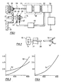
- the illustrative apparatus is for use in detecting variations around a circular path on the surface of a rotating disc 10 of a disc brake.
- the disc 10 is mounted on a shaft 12 for rotation about a central longitudinal axis 14 of the shaft 12.
- the circular path is centred on the axis 14.
- the illustrative apparatus comprises infra-red radiation detecting means which comprises two detectors 16 and 18 ( Figure 2) which are sensitive to different but neighbouring wavelength ranges.
- the detector 16 in this case, is a Germanium pyrometer and the detector 18 is an Indium Arsenide pyrometer.
- the illustrative apparatus also comprises radiation transmitting means in the form of a bundle of optical fibres 20 which is arranged to transmit infra-red radiation from an area A on said circular path to the detectors 16 and 18, the area A representing an arc of approximately 6 degrees of the circular path.
- the bundle 20 consists of 50 individual fibres which each has one of its ends supported adjacent to the area A by a support 22.
- the ends of the fibres supported by the support 22 are arranged on a circular area 21 facing the area A of the disc 10 and each fibre receives infra-red radiation emitted by the area A. It should be noted that the portion of the disc 10 which occupies the area A is constantly changing as the disc 10 rotates.
- the bundle 20 is split adjacent to the detectors 16 and 18, which are housed in a detector array 24, so that 25 of the fibres lead to each detector 16 and 18, the fibres leading to each detector 16 and 18 being randomly selected from across the area 21.
- a proportion i.e. half of the radiation collected by the bundle 20 from said area A is transmitted to each of the detectors 16 and 18. It is not, however, necessary that the proportion should be half.
- the support 22 also supports further bundles of optical fibres 26 which provide further radiation transmitting means arranged to transmit infra-red radiation from areas on different circular paths of the surface of the disc 10 to further sets of detectors (not shown) in the detector array 24.
- Each set of detectors has two detectors, one identical to the detector 16 and one identical to the detector 18.
- the bundles 20 and 26 pass through a protective conduit 28 to the array 24.
- the signals from the detectors in the array 24 are amplified by an amplifier 30 and passed to a high speed analogue to digital converter 32 and thence to a RAM memory 34.
- a computer 36 processes the data stored in the memory 34.
- the illustrative apparatus also comprises angular position detecting means operable to detect the angular position of the disc 10 relative to the axis 14.
- the angular position detecting means comprises two toothed wheels 38 and 40 mounted on the shaft 12 for rotation therewith, two proximity detectors 42 and 44, and a pulse shaper 46.
- the detector 42 is arranged to detect the teeth of the wheel 38 which has 60 equally-spaced teeth so that the position of the disc 10 about the axis 14 is detected in 6 degree increments.
- the wheel 40 has a single tooth which is detected by the detector 44 to provide a setting pulse.
- the signals from the detectors 42 and 44 are shaped by the shaper 46 and passed to the memory 34 via the converter 32.
- the memory 34 therefore, provides recording means of the illustrative apparatus operable to record the signals from the detectors 16, 18, 42 and 44 in relation to one another so that the temperature variations around the circular path on the surface of the disc 10 can be calculated.
- the outputs of the detectors 16 and 18 are recorded every time the detector 42 detects a pulse, i.e. every 6 degrees of rotation of the disc 10 and, as the area A represents approximately 6 degrees of arc, the temperatures over the whole circular path are detected.
- Figure 3 shows the output of the detectors 16 and 18 in volts (y-axis) plotted against the temperature of the area A in degrees Centigrade.
- the curve 50 represents the output of the detector 16 and the curve 52 that of the detector 18. Both the curves 50 and 52 are, however, subject to being depressed towards the x-axis by the effects of dust and dirt and emissivity which would, if the curve 50 or the curve 52 were used solely to indicate the temperature, depress the temperature value detected. For this reason, the output of the apparatus is calculated by the computer 36 as the ratio of the signals from the detectors 16 and 18.
- This output is illustrated by the curve 54 shown in Figure 4 which plots the value of the curve 50 divided by the curve 52 (y-axis) against the temperature of the area A. It will be observed that a well-defined curve is obtained.
- the curve 54 is substantially independent of the effects of dust and dirt and emissivity.
Landscapes
- Physics & Mathematics (AREA)
- General Physics & Mathematics (AREA)
- Spectroscopy & Molecular Physics (AREA)
- Radiation Pyrometers (AREA)
Applications Claiming Priority (3)
| Application Number | Priority Date | Filing Date | Title |
|---|---|---|---|
| GB91139667 | 1991-06-28 | ||
| GB919113966A GB9113966D0 (en) | 1991-06-28 | 1991-06-28 | Apparatus for temperature detection |
| PCT/GB1992/001038 WO1993000578A1 (en) | 1991-06-28 | 1992-06-10 | Apparatus for temperature detection |
Publications (2)
| Publication Number | Publication Date |
|---|---|
| EP0591257A1 EP0591257A1 (en) | 1994-04-13 |
| EP0591257B1 true EP0591257B1 (en) | 1996-08-21 |
Family
ID=10697481
Family Applications (1)
| Application Number | Title | Priority Date | Filing Date |
|---|---|---|---|
| EP92911480A Expired - Lifetime EP0591257B1 (en) | 1991-06-28 | 1992-06-10 | Apparatus for temperature detection |
Country Status (7)
| Country | Link |
|---|---|
| EP (1) | EP0591257B1 (da) |
| AU (1) | AU1913692A (da) |
| DE (1) | DE69213012T2 (da) |
| DK (1) | DK0591257T3 (da) |
| ES (1) | ES2090647T3 (da) |
| GB (2) | GB9113966D0 (da) |
| WO (1) | WO1993000578A1 (da) |
Families Citing this family (8)
| Publication number | Priority date | Publication date | Assignee | Title |
|---|---|---|---|---|
| FR2726081B1 (fr) * | 1994-10-21 | 1997-01-10 | Europ Propulsion | Pyrometre bichromatique rapide a fibre optique |
| GB9503274D0 (en) * | 1995-02-21 | 1995-04-12 | Sun Electric Uk Ltd | Method and apparatus for machine diagnosis |
| NL1003196C2 (nl) * | 1996-05-23 | 1997-11-25 | Kema Nv | Inrichting voor het contactloos meten van de temperatuur van bewegende lichamen. |
| US5963662A (en) * | 1996-08-07 | 1999-10-05 | Georgia Tech Research Corporation | Inspection system and method for bond detection and validation of surface mount devices |
| IL119956A (en) * | 1997-01-01 | 2003-11-23 | Opgal Optronic Ind Ltd | Brake monitoring system and method |
| DE102006013907A1 (de) * | 2006-03-25 | 2007-09-27 | Zf Friedrichshafen Ag | Verfahren und Vorrichtung zur Ermittlung der Temperatur eines oder mehrerer Reibelemente einer Reibschlussverbindung |
| DE102013213805B4 (de) * | 2013-07-15 | 2016-02-11 | Federal-Mogul Friction Products Gmbh | Bremsbelag und System zur Messung der Temperatur einer Bremse |
| ITBA20130072A1 (it) * | 2013-10-31 | 2015-05-01 | Mermec Spa | Sistema di sicurezza per applicazioni ferroviarie |
Family Cites Families (4)
| Publication number | Priority date | Publication date | Assignee | Title |
|---|---|---|---|---|
| DE3020331A1 (de) * | 1980-05-29 | 1981-12-17 | Industrie-Automation Gmbh & Co, 6900 Heidelberg | Vorrichtung zum erkennen unzulaessig erwaermter bauteile an fahrenden eisenbahnwagen |
| GB2118715B (en) * | 1982-04-16 | 1985-07-10 | Land Infrared Ltd | Validating rotor segment temperature |
| US4579461A (en) * | 1983-02-14 | 1986-04-01 | United States Steel Corporation | Dual sensor radiation pyrometer |
| GB2198529B (en) * | 1986-12-10 | 1991-01-09 | Smiths Industries Plc | Optical pyrometer |
-
1991
- 1991-06-28 GB GB919113966A patent/GB9113966D0/en active Pending
-
1992
- 1992-06-10 GB GB9212257A patent/GB2257508B/en not_active Expired - Fee Related
- 1992-06-10 DE DE69213012T patent/DE69213012T2/de not_active Expired - Fee Related
- 1992-06-10 DK DK92911480.9T patent/DK0591257T3/da active
- 1992-06-10 AU AU19136/92A patent/AU1913692A/en not_active Abandoned
- 1992-06-10 WO PCT/GB1992/001038 patent/WO1993000578A1/en not_active Ceased
- 1992-06-10 ES ES92911480T patent/ES2090647T3/es not_active Expired - Lifetime
- 1992-06-10 EP EP92911480A patent/EP0591257B1/en not_active Expired - Lifetime
Also Published As
| Publication number | Publication date |
|---|---|
| WO1993000578A1 (en) | 1993-01-07 |
| GB9113966D0 (en) | 1991-08-14 |
| GB9212257D0 (en) | 1992-07-22 |
| EP0591257A1 (en) | 1994-04-13 |
| DE69213012T2 (de) | 1997-02-13 |
| DE69213012D1 (de) | 1996-09-26 |
| GB2257508B (en) | 1994-11-16 |
| GB2257508A (en) | 1993-01-13 |
| AU1913692A (en) | 1993-01-25 |
| DK0591257T3 (da) | 1996-09-09 |
| ES2090647T3 (es) | 1996-10-16 |
Similar Documents
| Publication | Publication Date | Title |
|---|---|---|
| EP0591257B1 (en) | Apparatus for temperature detection | |
| US5054935A (en) | Temperature-measuring method and distributed optical fiber temperature sensor | |
| EP0729018B1 (en) | Method and apparatus for brake testing | |
| EP0169657B1 (en) | Non-contact shaft angle detector | |
| GB2101307A (en) | Error detecting system of video/audio disc player | |
| ES400581A1 (es) | Un aparato para leer, por medio de un haz de radiacion, un soporte o medio portador de informacion de forma discoidal, que contiene senales de video yno de audio codificadas en forma optica. | |
| US5507576A (en) | Bichromatic pyrometer | |
| GB2072836A (en) | Hot box detector systems | |
| DK309884A (da) | Sporfoelgesystem med en optisk aftaster til et audio- eller videopladegengiveapparat | |
| GB2172992A (en) | Radiation thermometer | |
| US4644163A (en) | Material identification using infrared thermometry | |
| Hernberg et al. | Simultaneous in situ measurement of temperature and size of burning char particles in a fluidized bed furnace by means of fiberoptic pyrometry | |
| JP3404976B2 (ja) | コンベア温度監視装置 | |
| JPH03501278A (ja) | リファイナーにおいて接触位置を指示する方法及び装置 | |
| KR970705010A (ko) | 환경 감시 장치 | |
| JPH0585014B2 (da) | ||
| GB1595683A (en) | Optically reproducing system | |
| TR200001650T1 (tr) | Optik disk ve taranması için cihaz | |
| EP0100399A2 (en) | Method and apparatus for identifying material | |
| JP2602981B2 (ja) | 温度分布検出装置 | |
| GB2089972A (en) | Noise filter for combustion gas analyzer | |
| JPH0684912B2 (ja) | 温度計 | |
| SU1462123A1 (ru) | Устройство дл измерени параметров вращающихс объектов | |
| JPH0652195B2 (ja) | 赤外線温度計 | |
| EP0651377A1 (en) | Position sensors for computer disk drives |
Legal Events
| Date | Code | Title | Description |
|---|---|---|---|
| PUAI | Public reference made under article 153(3) epc to a published international application that has entered the european phase |
Free format text: ORIGINAL CODE: 0009012 |
|
| 17P | Request for examination filed |
Effective date: 19931116 |
|
| AK | Designated contracting states |
Kind code of ref document: A1 Designated state(s): DE DK ES FR GB IT SE |
|
| 17Q | First examination report despatched |
Effective date: 19950921 |
|
| GRAH | Despatch of communication of intention to grant a patent |
Free format text: ORIGINAL CODE: EPIDOS IGRA |
|
| ITF | It: translation for a ep patent filed | ||
| GRAA | (expected) grant |
Free format text: ORIGINAL CODE: 0009210 |
|
| AK | Designated contracting states |
Kind code of ref document: B1 Designated state(s): DE DK ES FR GB IT SE |
|
| REG | Reference to a national code |
Ref country code: DK Ref legal event code: T3 |
|
| REF | Corresponds to: |
Ref document number: 69213012 Country of ref document: DE Date of ref document: 19960926 |
|
| ET | Fr: translation filed | ||
| REG | Reference to a national code |
Ref country code: ES Ref legal event code: FG2A Ref document number: 2090647 Country of ref document: ES Kind code of ref document: T3 |
|
| REG | Reference to a national code |
Ref country code: ES Ref legal event code: FG2A Ref document number: 2090647 Country of ref document: ES Kind code of ref document: T3 |
|
| PLBE | No opposition filed within time limit |
Free format text: ORIGINAL CODE: 0009261 |
|
| STAA | Information on the status of an ep patent application or granted ep patent |
Free format text: STATUS: NO OPPOSITION FILED WITHIN TIME LIMIT |
|
| 26N | No opposition filed | ||
| PGFP | Annual fee paid to national office [announced via postgrant information from national office to epo] |
Ref country code: FR Payment date: 20010723 Year of fee payment: 10 |
|
| PGFP | Annual fee paid to national office [announced via postgrant information from national office to epo] |
Ref country code: SE Payment date: 20010724 Year of fee payment: 10 |
|
| PGFP | Annual fee paid to national office [announced via postgrant information from national office to epo] |
Ref country code: DK Payment date: 20010725 Year of fee payment: 10 |
|
| PGFP | Annual fee paid to national office [announced via postgrant information from national office to epo] |
Ref country code: ES Payment date: 20010731 Year of fee payment: 10 Ref country code: DE Payment date: 20010731 Year of fee payment: 10 |
|
| PGFP | Annual fee paid to national office [announced via postgrant information from national office to epo] |
Ref country code: GB Payment date: 20010807 Year of fee payment: 10 |
|
| REG | Reference to a national code |
Ref country code: GB Ref legal event code: IF02 |
|
| PG25 | Lapsed in a contracting state [announced via postgrant information from national office to epo] |
Ref country code: GB Free format text: LAPSE BECAUSE OF NON-PAYMENT OF DUE FEES Effective date: 20020610 |
|
| PG25 | Lapsed in a contracting state [announced via postgrant information from national office to epo] |
Ref country code: SE Free format text: LAPSE BECAUSE OF NON-PAYMENT OF DUE FEES Effective date: 20020611 Ref country code: ES Free format text: LAPSE BECAUSE OF NON-PAYMENT OF DUE FEES Effective date: 20020611 |
|
| PG25 | Lapsed in a contracting state [announced via postgrant information from national office to epo] |
Ref country code: DK Free format text: LAPSE BECAUSE OF NON-PAYMENT OF DUE FEES Effective date: 20020731 |
|
| PG25 | Lapsed in a contracting state [announced via postgrant information from national office to epo] |
Ref country code: DE Free format text: LAPSE BECAUSE OF NON-PAYMENT OF DUE FEES Effective date: 20030101 |
|
| REG | Reference to a national code |
Ref country code: DK Ref legal event code: EBP |
|
| GBPC | Gb: european patent ceased through non-payment of renewal fee |
Effective date: 20020610 |
|
| EUG | Se: european patent has lapsed | ||
| PG25 | Lapsed in a contracting state [announced via postgrant information from national office to epo] |
Ref country code: FR Free format text: LAPSE BECAUSE OF NON-PAYMENT OF DUE FEES Effective date: 20030228 |
|
| REG | Reference to a national code |
Ref country code: FR Ref legal event code: ST |
|
| REG | Reference to a national code |
Ref country code: ES Ref legal event code: FD2A Effective date: 20030711 |
|
| PG25 | Lapsed in a contracting state [announced via postgrant information from national office to epo] |
Ref country code: IT Free format text: LAPSE BECAUSE OF NON-PAYMENT OF DUE FEES;WARNING: LAPSES OF ITALIAN PATENTS WITH EFFECTIVE DATE BEFORE 2007 MAY HAVE OCCURRED AT ANY TIME BEFORE 2007. THE CORRECT EFFECTIVE DATE MAY BE DIFFERENT FROM THE ONE RECORDED. Effective date: 20050610 |
|
| REG | Reference to a national code |
Ref country code: FR Ref legal event code: CP |