EP0591164B1 - Combination vacuum/pressure pump and valve stopper for food or drink containers - Google Patents
Combination vacuum/pressure pump and valve stopper for food or drink containers Download PDFInfo
- Publication number
- EP0591164B1 EP0591164B1 EP91904541A EP91904541A EP0591164B1 EP 0591164 B1 EP0591164 B1 EP 0591164B1 EP 91904541 A EP91904541 A EP 91904541A EP 91904541 A EP91904541 A EP 91904541A EP 0591164 B1 EP0591164 B1 EP 0591164B1
- Authority
- EP
- European Patent Office
- Prior art keywords
- valve
- pump
- opening
- stopper
- vacuum
- Prior art date
- Legal status (The legal status is an assumption and is not a legal conclusion. Google has not performed a legal analysis and makes no representation as to the accuracy of the status listed.)
- Expired - Lifetime
Links
- 235000013305 food Nutrition 0.000 title claims abstract description 41
- 238000007789 sealing Methods 0.000 claims abstract description 17
- 230000002441 reversible effect Effects 0.000 claims abstract description 4
- 235000001674 Agaricus brunnescens Nutrition 0.000 claims description 50
- 235000013361 beverage Nutrition 0.000 claims description 18
- 238000005086 pumping Methods 0.000 claims description 5
- 230000000717 retained effect Effects 0.000 claims description 5
- 230000009977 dual effect Effects 0.000 description 6
- 239000004033 plastic Substances 0.000 description 5
- 229920003023 plastic Polymers 0.000 description 5
- 239000000463 material Substances 0.000 description 3
- 235000014101 wine Nutrition 0.000 description 3
- DHKHKXVYLBGOIT-UHFFFAOYSA-N 1,1-Diethoxyethane Chemical compound CCOC(C)OCC DHKHKXVYLBGOIT-UHFFFAOYSA-N 0.000 description 2
- CDBYLPFSWZWCQE-UHFFFAOYSA-L Sodium Carbonate Chemical compound [Na+].[Na+].[O-]C([O-])=O CDBYLPFSWZWCQE-UHFFFAOYSA-L 0.000 description 2
- PPBRXRYQALVLMV-UHFFFAOYSA-N Styrene Chemical compound C=CC1=CC=CC=C1 PPBRXRYQALVLMV-UHFFFAOYSA-N 0.000 description 2
- 125000000218 acetic acid group Chemical group C(C)(=O)* 0.000 description 2
- 239000004676 acrylonitrile butadiene styrene Substances 0.000 description 2
- 238000000034 method Methods 0.000 description 2
- 229920005989 resin Polymers 0.000 description 2
- 239000011347 resin Substances 0.000 description 2
- 235000015040 sparkling wine Nutrition 0.000 description 2
- 229920002633 Kraton (polymer) Polymers 0.000 description 1
- 229920004142 LEXAN™ Polymers 0.000 description 1
- 239000004418 Lexan Substances 0.000 description 1
- NIXOWILDQLNWCW-UHFFFAOYSA-N acrylic acid group Chemical group C(C=C)(=O)O NIXOWILDQLNWCW-UHFFFAOYSA-N 0.000 description 1
- XECAHXYUAAWDEL-UHFFFAOYSA-N acrylonitrile butadiene styrene Chemical compound C=CC=C.C=CC#N.C=CC1=CC=CC=C1 XECAHXYUAAWDEL-UHFFFAOYSA-N 0.000 description 1
- 229920000122 acrylonitrile butadiene styrene Polymers 0.000 description 1
- 235000014171 carbonated beverage Nutrition 0.000 description 1
- 235000019993 champagne Nutrition 0.000 description 1
- 238000004140 cleaning Methods 0.000 description 1
- 238000010276 construction Methods 0.000 description 1
- 230000007423 decrease Effects 0.000 description 1
- 230000006866 deterioration Effects 0.000 description 1
- 239000003814 drug Substances 0.000 description 1
- 229940079593 drug Drugs 0.000 description 1
- 238000009920 food preservation Methods 0.000 description 1
- 239000007788 liquid Substances 0.000 description 1
- 230000013011 mating Effects 0.000 description 1
- 230000003647 oxidation Effects 0.000 description 1
- 238000007254 oxidation reaction Methods 0.000 description 1
- 239000004417 polycarbonate Substances 0.000 description 1
- 229920000515 polycarbonate Polymers 0.000 description 1
- 229920000642 polymer Polymers 0.000 description 1
- 239000004576 sand Substances 0.000 description 1
- 229920005573 silicon-containing polymer Polymers 0.000 description 1
- 239000000126 substance Substances 0.000 description 1
- 229920001169 thermoplastic Polymers 0.000 description 1
- 229920005992 thermoplastic resin Polymers 0.000 description 1
- 239000004416 thermosoftening plastic Substances 0.000 description 1
Images

Classifications
-
- B—PERFORMING OPERATIONS; TRANSPORTING
- B65—CONVEYING; PACKING; STORING; HANDLING THIN OR FILAMENTARY MATERIAL
- B65B—MACHINES, APPARATUS OR DEVICES FOR, OR METHODS OF, PACKAGING ARTICLES OR MATERIALS; UNPACKING
- B65B31/00—Packaging articles or materials under special atmospheric or gaseous conditions; Adding propellants to aerosol containers
- B65B31/04—Evacuating, pressurising or gasifying filled containers or wrappers by means of nozzles through which air or other gas, e.g. an inert gas, is withdrawn or supplied
- B65B31/046—Evacuating, pressurising or gasifying filled containers or wrappers by means of nozzles through which air or other gas, e.g. an inert gas, is withdrawn or supplied the nozzles co-operating, or being combined, with a device for opening or closing the container or wrapper
- B65B31/047—Evacuating, pressurising or gasifying filled containers or wrappers by means of nozzles through which air or other gas, e.g. an inert gas, is withdrawn or supplied the nozzles co-operating, or being combined, with a device for opening or closing the container or wrapper the nozzles co-operating with a check valve in the opening of the container or wrapper
Definitions
- This invention relates to hand operated pumps for pressurising and evacuating food or drink containers and to one-way vacuum and pressure valve stoppers used in conjunction with such pumps to maintain the generated pressure or vacuum.
- Vacuum storage removes the air and prevents oxidation of the food or beverage which is a principal cause of food deterioration.
- liquids such as carbonated beverages and sparkling wines need pressure storage to prevent the escape of the gaseous material.
- Pressure pumps suitable for use with pressure valve stoppers such as are shown in United States Patent 3,084,823 are also known.
- a principal object of the present invention is to provide a single pump which may be used in both a pressure and a vacuum configuration.
- a second object of the invention is to provide a valve stopper for use with food and beverage containers which may be reversed between a pressure and a vacuum configuration.
- Still another object of the invention is to provide a valve stopper which may be easily activated to release the vacuum or pressure within the food or drink container and permit removal of the stopper.
- the present invention provides a combination pressure and vacuum pump for food or drink containers.
- the pump comprises a pump housing containing a pump cylinder, a pump head adapted for sealing engagement with a valve stopper on a food or drink container, a piston in sliding airtight engagement with the pump cylinder, and a handle adapted for hand pumping to move the piston and the pump cylinder relative to one another.
- the pump cylinder, pump head and piston define a pump chamber, including a first opening which connects to the valve stopper when the pump head is sealed to the valve stopper for pumping a gas into or out of the food or drink container, and a second opening which connects to the atmosphere through a combination pressure and vacuum valve.
- the combination valve is switchable from a vacuum position to a pressure position.
- the invention also comprises a combination pressure and vacuum valve stopper for food and beverage containers which includes a stopper element which seals to the opening in the food or beverage container and to the pump head.
- the stopper includes a valve opening through the stopper for the passage of air into or out of the food/drink container, and a valve element which is retained by the valve opening in the stopper.
- the valve opening is reversable between a pressure position and a vacuum position to seal the valve opening in the two orientations.
- the invention also comprises the combination of the pressure/vacuum pump and the reversable pressure/vacuum valve stopper.
- Figure 1 is a front elevational view of the combination vacuum and pressure pump of the present invention positioned above a stopper valve on a beverage container.
- Figure 2 is a cross sectional view along the line 2-2 in Figure 1 showing the pump of the invention with the switchable vacuum/pressure valve in the vacuum position, the pump handle being shown in solid line in the lowered position.
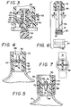
- Figure 3 shows a detail cross sectional view of the switchable vacuum/pressure dual mushroom (or “umbrella”) pump valve in the pressure position and the piston on which the valve is mounted.
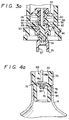
- Figure 3a shows an alternate embodiment of the pump valve depicted in Fig. 3.
- Figure 4 shows a one-way valve stopper in the vacuum configuration according to the present invention.
- Figure 4a shows an alternate embodiment of the one way stopper depicted in Fig. 4.
- Figure 5 shows a screw cap one-way pressure valve stopper in the pressure configuration according to the present invention.
- Figure 6 shows a front elevational dissassembled view of the preferred embodiment of the piston rod and piston of the present invention with the handle being shown in cross section to illustrate its connection to the piston rod.
- Figure 7 shows a cross sectional view of the piston rod and pump handle along the line 7-7 in Fig. 6.
- the combination vacuum/pressure pump shown in Figures 1-2 operates in conjunction with the vacuum/pressure valve stoppers shown in Figures 4-5 to pressurize or evacuate food and drink storage containers. Both the pump and the valve stoppers are switchable between pressure and vacuum operation for maximum flexibility of the food preservation system.
- the combination vacuum/pressure pump is indicated generally by reference numeral 10.
- the corresponding valve stopper 12 is shown below the pump 10 just prior to engagement of the two for pressurizing or evacuating the food storage container 14.
- the pump comprises a housing 16, a handle 18, and a pump head 20.
- the pump head 20 is threadably attached to the interior of the pump housing 16 via threads 22.
- a knurled ring 24 formed on the perimeter of the pump head 20 permits the pump head to be easily unthreaded and removed from the pump housing 16. This provides access to knob 26 which is pushed longitudinally to switch the pump from the vacuum pump position (shown in Figure 2) to the pressure pump position (shown in Figure 3).
- the pump head is sealed to the pump housing by O-ring 28.
- the pump head 20 is adapted for sealing engagement with the valve stoppers of Figures 4-5.
- the exterior of the pump head 20 is conical and tapers from the outer diameter of the pump housing towards the centerline of the pump adjacent to the valve stopper. This conical design permits the pump head 20 to seal against the inner lip 30 of the valve stoppers of Figures 4 and 5.
- this conical sealing system is preferred because it fits varying internal diameters of one-way valve stoppers, alternative configurations are also suitable in which the pump engages the exterior of the valve stopper or in which a face-to-face or clamping seal is provided.
- the housing 16 incorporates cylinder 32 within its interior. Piston 34 slides longitudinally within the cylinder 32 as the pump handle is moved between the lowered position seen in Figure 2 and a raised position (not shown).
- the piston includes a resilient sealing ring 36 which forms an airtight seal between the piston 34 and the cylinder 32.
- Piston rod 38 connects the piston 34 to the handle 18.
- the piston rod 38 is hollow and forms a single piece with piston 34.
- the piston rod 38 has an "X" shaped cross section and is threadably attached to a separate piston.
- the cylinder 32, piston 34, and pump head 20 define a pump chamber which increases and decreases in volume as the piston is pumped up and down.
- the pump chamber is connected to the interior of the food/drink container 14 through a first opening 40 which passes through the pump head which is in turn sealed to the valve stopper.
- the second opening 42 to the pump chamber is through the combination pressure and vacuum valve (shown in detail in Figure 3) which connects the pump chamber to the atmosphere.
- the combination vacuum/pressure valve is preferably mounted on the piston 34, but may alternatively be mounted elsewhere so as to connect the pump chamber to atmospheric pressure through the switchable valve.
- the pump valve comprises a dual mushroom valve longitudinally slidable between a pressure and a vacuum position.
- the two mushroom valve elements 44, 46 include flexible sealing skirts at their perimeters and are mounted opposite one another along the valve rod formed of the vacuum valve rod portion 48 and the pressure valve rod portion 50.
- the valve rod 48, 50 is in the position seen in Figure 2.
- the sealing skirt of the vacuum mushroom valve element 44 seals against the upper surface of the piston 34.
- the pressure mushroom valve element 46 serves no function.
- valve rod 48, 50 Prior to pressure operation, the valve rod 48, 50 is moved longitudinally upwards to the position shown in Figure 3 such that the sealing skirt on the pressure mushroom valve element 46 contacts the opposite surface of the piston 34. During pressure operation, the vacuum mushroom valve element 44 serves no function.
- valve rod portion 48 projects through opening 42 in the piston 34 to connect the pump chamber to the atmosphere.
- the interior of the piston rod 38 is open to the atmosphere through a pressure relief hole 52.
- a separate pressure relief hole is not required as the piston rod 38 is directly open to the atmosphere.
- Knob 26 is formed as part of the pressure valve rod portion 50 and moves the entire valve assembly longitudinally to bring the vacuum mushroom valve element 44 and the pressure mushroom valve element 46 into and out of contact with the upper and lower faces of the piston 34.
- knob 26 includes a downwardly extending annular sleeve having a central opening 27. As will be discussed below, this central opening prevents interference of knob 26 with an alternate embodiment of the stopper with which the pump is used.
- the complete valve assembly comprises four components, namely the vacuum and pressure mushrooms 44, 46, the (upper) vacuum valve rod portion 48 and the (lower) pressure valve rod portion 50 which incorporates the knob 26.
- the mushroom valves 44, 46 are positioned on their respective valve rod portions which are then assembled through the second opening 42 in the piston 34 by inserting the arrowhead lock 54 on the vacuum valve rod portion 48 into a mating receptacle in the interior of the pressure valve rod portion 50.
- the valve rod includes detent bumps 56 mounted at the ends of flexible fingers 58 which are longitudinally aligned with the axis of the valve rod.
- the fingers 58 and valve rod portions 48, 50 are formed of a plastic which is resilient and permits the fingers 58 to bend radially inward, swinging the detent bumps out of the way as the valve is moved from the pressure to the vacuum position.
- valve rod portions 48, 50 include annular stop rings 60, 62 which prevent the valve rod from passing through the opening 42 in the piston and provide a convenient mount for the mushroom valve elements 44, 46.
- the valve rod portion 48 includes longitudinally aligned air passageways 64 which permit air to pass through the opening 42 during the pressure and/or vacuum strokes.
- the longitudinal passageways 64 connect to radial passageways 66 on the surface of the annular stop rings so that the stop rings do not obstruct the air flow.
- other openings may be provided in the piston adjacent to opening 42 to permit passage of air.
- the valve stopper in Figure 4 is shown in the vacuum configuration and comprises a resilient stopper 70 adapted to contact and seal the opening in a food or drink container 14.
- a central opening 72 in the stopper 70 loosely holds the mushroom valve 68.
- the mushroom valve 68 includes a large head portion 74 connected to a smaller stop button 76 via valve rod 78.
- the mushroom head portion 74 corresponds in function to the mushroom valves 44, 46 in Figure 3 and acts to seal the valve stopper by making sealing contact around the perimeter of opening 72.
- the mushroom head portion 74 rises up, and stop button 76 acts to retain the mushroom valve 68 in opening 72.
- stop button 76 acts to retain the mushroom valve 68 in opening 72.
- the valve rod and retaining button would obstruct the flow of air or gas out of the food/drink container 14.
- the valve rod may be constructed with a smaller diameter than opening 72, in which case the retaining button 76 should have grooves or openings to allow air passage around the rod.
- the stopper 70 includes a lower half adapted to contact the interior of a wine bottle neck or food container opening and an upper half of a larger diameter which rests upon the rim of the container. Ridges 84 help provide an airtight seal with the interior of the food container.
- the inner lip 30 of the stopper has a diameter intermediate the minimum and maximum diameters of the conical pump head 16 so as to provide an airtight seal as the pump is pressed against the stopper during pumping.
- mushroom head portion 74 is provided with an extended tip at its upper end which allows the mushroom valve to be rocked to one side or the other which releases the vacuum and allows removal of the stopper 70.
- mushroom valve 68 operates in the same manner previously described, but includes a head portion having a flat, disk shaped sealing portion 74a which seals around the perimeter of opening 72 and an upwardly extending shaft portion 74b whose tip extends to or above the top edge of stopper inner lip 30 for easier access for rocking and opening valve 68.
- the embodiment of pump know 26 having relief area 27 as shown in Figure 3a be utilized with the stopper embodiment shown in Figure 4a to avoid any potential interference by permitting the top of valve 68 to be received within the open area of knob 26.
- Figure 5 shows a similar valve stopper in the pressure configuration, in which like components have been designated with like numerals.
- the stopper 70 has been retained inside a threaded cap 86 which is attached via threads 88 to the top of a threaded food or beverage container.
- the cap may be provided with threading to match carbonated soda bottles or to fit the top of a champagne bottle, or a specially manufactured food or beverage container may be provided.
- the mushroom valve 68 in Figure 5 is identical to, but reversed from, the mushroom valve of Figure 4. This illustrates one of the principal advantages of the present invention in which the mushroom valve 68 may be reversed by pulling it out of the opening 72 and inserting it in the revised orientation. This switches the stopper valve from pressure stopper operation as seen in Figure 5 to vacuum stopper operation as in Figure 4.
- the threaded stopper attachment method of Figure 5 is preferred for both pressure and vacuum stopper operation
- the simple unthreaded stopper of Figure 4 may also be used in the pressure mode, particularly where the neck of the beverage container narrows towards the outlet of the bottle, where a rough surface on the interior of the neck is provided, or where only a low pressure needs to be maintained.
- Figures 6 and 7 show the preferred embodiment of the piston rod 38, piston 34 and handle 18.
- the lower end of the piston rod 38 in Figure 6 includes threads 90 which engage corresponding threads on the interior of piston 34. Openings 91 extend through the lower threaded portion of piston rod 38 to permit air passage between the exterior of rod 38 and piston opening 42.
- the upper end of the piston rod is cylindrical and contains a bump ring 92 which engages a groove 94 on the inner surface of handle 18 so that they may be snapped together.
- the pump rod 38 has been shown in elevation in Figure 7, and the handle 18 has been shown in cross section to illustrate this interconnection method.
- Figure 7 is taken along the cross sectional line 7-7 in Figure 6 and shows the "X" shape of the piston rod 38.
- the "X” shape provides direct access to the atmosphere, as required for the dual mushroom valve.
- the "X" configuration provides greater clearance from the interior surface of the cylinder 32 which prevents damage due to dirt or sand being trapped between the exterior of the piston rod and the interior of the cylinder 32. In the preferred design, this debris falls into the interior of the piston where it is retained until the unit is cleaned without damage to the inner surface of the cylinder.
- the piston may be unthreaded from the piston rod which makes cleaning the pump much easier, and also allows the pump to be modified or fitted with new valves or different valve configurations.
- a stopper of the type seen in Figures 4 or 5 is selected which is suitable for the beverage/food container to be used.
- the container may be a conventional wine bottle, or it may be a food container specially prepared for use in combination with the threaded stopper of Figure 5. If necessary, the mushroom valve 68 in the selected stopper may be reversed to change the stopper operation from pressure to vacuum.
- the pump 10 is then set for pressure or vacuum operation by unthreading the pump head 20, and sliding the knob 26 longitudinally into the appropriate pressure or vacuum position.
- the pump head 20 is then reattached to the pump housing and tightened to seal the O-ring 28.
- the pump is next positioned so that the conical position of the pump head 20 seals against the inner surface 30 of the selected valve stopper.
- the handle 18 is then grasped firmly and pumped up and down until resistance is felt and the desired pressure or vacuum is achieved
- the pump housing 16, handle 18, pump head 20, piston rod 38 and piston 34 are preferably made of a strong, impact resistant plastic such as Acrylonitrile-Butadiene-Styrene (ABS).
- ABS Acrylonitrile-Butadiene-Styrene
- the valve rod portions 48, 50 are preferably made from a thermoplastic acetyl resin such as Delrin 500, a tradename for this plastic which is available from EI DuPont de Nemours & Company.
- the mushroom valve elements 44, 46 and the stopper mushroom valves 68 are preferably made from a silicone polymer plastic.
- the mushroom valve 68 be made of an acetyl resin such as Delrin 500 or other stiffer polymers such as ABS or a polycarbonate such as Lexan available from E.I DuPont de Nemours & Company.
- the stopper 70 may be manufactured from a compounded thermoplastic resin such as Kraton 2712G which is available from Shell Chemical Company or from its licensees under the trade name Empilon.
- the threaded cap 86 is manufactured of a hard clear acrylic styrene.
- the portion of the plastic materials used in the construction of this pump for contact with foods and beverages should be suitable for use with such foods and beverages, and appropriate materials will have been approved by the United States Food and Drug Administration.
Landscapes
- Chemical & Material Sciences (AREA)
- Dispersion Chemistry (AREA)
- Engineering & Computer Science (AREA)
- Mechanical Engineering (AREA)
- Compressors, Vaccum Pumps And Other Relevant Systems (AREA)
- Cold Air Circulating Systems And Constructional Details In Refrigerators (AREA)
- Tea And Coffee (AREA)
- Food Preservation Except Freezing, Refrigeration, And Drying (AREA)
- Closures For Containers (AREA)
- Central Air Conditioning (AREA)
- Vacuum Packaging (AREA)
Abstract
Description
- This invention relates to hand operated pumps for pressurising and evacuating food or drink containers and to one-way vacuum and pressure valve stoppers used in conjunction with such pumps to maintain the generated pressure or vacuum.
- It is well known that certain beverages and foods, such as wine and ground coffee, are preserved best under a vacuum, while others, such as carbonated soda and sparkling wines, do best under pressure. Vacuum storage removes the air and prevents oxidation of the food or beverage which is a principal cause of food deterioration. Conversely, liquids such as carbonated beverages and sparkling wines need pressure storage to prevent the escape of the gaseous material.
- These contrasting food/beverage storage requirements have heretofore been met separately. For example, United States Patent Nos. 4,249,583; 4,142,645 and 2,049,872 show vacuum pumps, operable with suitable one-way valve vacuum stoppers, for removing the air from food or beverage containers.
- Pressure pumps suitable for use with pressure valve stoppers such as are shown in United States Patent 3,084,823 are also known.
- Finally United States Patent No. 4,763,803 to Schneider discloses a vacuum pump having a mushroom valve the position of which determines whether the pump will pressure or evacuate the container, accordingly it is necessary to completely remove the valve from the opening in the pump piston in order to switch it between vacuum and pressure positions. Furthermore the Schneider patent discloses an integral slit-type valve in the stopper in contrast with this invention wherein a reversible valve element is provided therein.
- Accordingly, a principal object of the present invention is to provide a single pump which may be used in both a pressure and a vacuum configuration.
- A second object of the invention is to provide a valve stopper for use with food and beverage containers which may be reversed between a pressure and a vacuum configuration.
- Still another object of the invention is to provide a valve stopper which may be easily activated to release the vacuum or pressure within the food or drink container and permit removal of the stopper.
- The present invention provides a combination pressure and vacuum pump for food or drink containers. The pump comprises a pump housing containing a pump cylinder, a pump head adapted for sealing engagement with a valve stopper on a food or drink container, a piston in sliding airtight engagement with the pump cylinder, and a handle adapted for hand pumping to move the piston and the pump cylinder relative to one another. The pump cylinder, pump head and piston define a pump chamber, including a first opening which connects to the valve stopper when the pump head is sealed to the valve stopper for pumping a gas into or out of the food or drink container, and a second opening which connects to the atmosphere through a combination pressure and vacuum valve. The combination valve is switchable from a vacuum position to a pressure position. The invention also comprises a combination pressure and vacuum valve stopper for food and beverage containers which includes a stopper element which seals to the opening in the food or beverage container and to the pump head. The stopper includes a valve opening through the stopper for the passage of air into or out of the food/drink container, and a valve element which is retained by the valve opening in the stopper. The valve opening is reversable between a pressure position and a vacuum position to seal the valve opening in the two orientations.
- The invention also comprises the combination of the pressure/vacuum pump and the reversable pressure/vacuum valve stopper.
- Figure 1 is a front elevational view of the combination vacuum and pressure pump of the present invention positioned above a stopper valve on a beverage container.
- Figure 2 is a cross sectional view along the line 2-2 in Figure 1 showing the pump of the invention with the switchable vacuum/pressure valve in the vacuum position, the pump handle being shown in solid line in the lowered position.
- Figure 3 shows a detail cross sectional view of the switchable vacuum/pressure dual mushroom (or "umbrella") pump valve in the pressure position and the piston on which the valve is mounted.
- Figure 3a shows an alternate embodiment of the pump valve depicted in Fig. 3.
- Figure 4 shows a one-way valve stopper in the vacuum configuration according to the present invention.
- Figure 4a shows an alternate embodiment of the one way stopper depicted in Fig. 4.
- Figure 5 shows a screw cap one-way pressure valve stopper in the pressure configuration according to the present invention.
- Figure 6 shows a front elevational dissassembled view of the preferred embodiment of the piston rod and piston of the present invention with the handle being shown in cross section to illustrate its connection to the piston rod.
- Figure 7 shows a cross sectional view of the piston rod and pump handle along the line 7-7 in Fig. 6.
- The combination vacuum/pressure pump shown in Figures 1-2 operates in conjunction with the vacuum/pressure valve stoppers shown in Figures 4-5 to pressurize or evacuate food and drink storage containers. Both the pump and the valve stoppers are switchable between pressure and vacuum operation for maximum flexibility of the food preservation system.
- Referring to Figure 1, the combination vacuum/pressure pump is indicated generally by
reference numeral 10. Thecorresponding valve stopper 12 is shown below thepump 10 just prior to engagement of the two for pressurizing or evacuating thefood storage container 14. The pump comprises ahousing 16, ahandle 18, and apump head 20. - Referring to Figure 2, the
pump head 20 is threadably attached to the interior of thepump housing 16 viathreads 22. Aknurled ring 24 formed on the perimeter of thepump head 20 permits the pump head to be easily unthreaded and removed from thepump housing 16. This provides access toknob 26 which is pushed longitudinally to switch the pump from the vacuum pump position (shown in Figure 2) to the pressure pump position (shown in Figure 3). The pump head is sealed to the pump housing by O-ring 28. - The
pump head 20 is adapted for sealing engagement with the valve stoppers of Figures 4-5. The exterior of thepump head 20 is conical and tapers from the outer diameter of the pump housing towards the centerline of the pump adjacent to the valve stopper. This conical design permits thepump head 20 to seal against theinner lip 30 of the valve stoppers of Figures 4 and 5. Although this conical sealing system is preferred because it fits varying internal diameters of one-way valve stoppers, alternative configurations are also suitable in which the pump engages the exterior of the valve stopper or in which a face-to-face or clamping seal is provided. - The
housing 16 incorporatescylinder 32 within its interior. Piston 34 slides longitudinally within thecylinder 32 as the pump handle is moved between the lowered position seen in Figure 2 and a raised position (not shown). The piston includes aresilient sealing ring 36 which forms an airtight seal between thepiston 34 and thecylinder 32. - Piston rod 38 connects the
piston 34 to thehandle 18. In the embodiment of Figure 2, thepiston rod 38 is hollow and forms a single piece withpiston 34. However, in the more highly preferred embodiment seen in Figures 6-7, in which like numerals designate like features, thepiston rod 38 has an "X" shaped cross section and is threadably attached to a separate piston. - The
cylinder 32,piston 34, andpump head 20 define a pump chamber which increases and decreases in volume as the piston is pumped up and down. The pump chamber is connected to the interior of the food/drink container 14 through afirst opening 40 which passes through the pump head which is in turn sealed to the valve stopper. Thesecond opening 42 to the pump chamber is through the combination pressure and vacuum valve (shown in detail in Figure 3) which connects the pump chamber to the atmosphere. The combination vacuum/pressure valve is preferably mounted on thepiston 34, but may alternatively be mounted elsewhere so as to connect the pump chamber to atmospheric pressure through the switchable valve. - As may be seen in Figure 2, and in greater detail in Figure 3, the pump valve comprises a dual mushroom valve longitudinally slidable between a pressure and a vacuum position.
- The two
mushroom valve elements valve rod portion 48 and the pressurevalve rod portion 50. During vacuum operation, thevalve rod mushroom valve element 44 seals against the upper surface of thepiston 34. During vacuum operation, the pressuremushroom valve element 46 serves no function. - Prior to pressure operation, the
valve rod mushroom valve element 46 contacts the opposite surface of thepiston 34. During pressure operation, the vacuummushroom valve element 44 serves no function. - The
valve rod portion 48 projects through opening 42 in thepiston 34 to connect the pump chamber to the atmosphere. In the embodiment of Figure 2, the interior of thepiston rod 38 is open to the atmosphere through apressure relief hole 52. In the embodiment seen in Figures 6 and 7, a separate pressure relief hole is not required as thepiston rod 38 is directly open to the atmosphere. -
Knob 26 is formed as part of the pressurevalve rod portion 50 and moves the entire valve assembly longitudinally to bring the vacuummushroom valve element 44 and the pressuremushroom valve element 46 into and out of contact with the upper and lower faces of thepiston 34. In an alternate embodiment depicted in Figure 3a,knob 26 includes a downwardly extending annular sleeve having acentral opening 27. As will be discussed below, this central opening prevents interference ofknob 26 with an alternate embodiment of the stopper with which the pump is used. - In the preferred design, the complete valve assembly comprises four components, namely the vacuum and
pressure mushrooms valve rod portion 48 and the (lower) pressurevalve rod portion 50 which incorporates theknob 26. - The
mushroom valves second opening 42 in thepiston 34 by inserting thearrowhead lock 54 on the vacuumvalve rod portion 48 into a mating receptacle in the interior of the pressurevalve rod portion 50. - The valve rod includes detent bumps 56 mounted at the ends of
flexible fingers 58 which are longitudinally aligned with the axis of the valve rod. Thefingers 58 andvalve rod portions fingers 58 to bend radially inward, swinging the detent bumps out of the way as the valve is moved from the pressure to the vacuum position. - The
valve rod portions opening 42 in the piston and provide a convenient mount for themushroom valve elements - As is customary in mushroom valves, the
valve rod portion 48 includes longitudinally alignedair passageways 64 which permit air to pass through theopening 42 during the pressure and/or vacuum strokes. Thelongitudinal passageways 64 connect toradial passageways 66 on the surface of the annular stop rings so that the stop rings do not obstruct the air flow. Instead of or in addition toair passageways 64, other openings may be provided in the piston adjacent to opening 42 to permit passage of air. - The complexity of the dual mushroom valve shown in Figure 3 somewhat obscures the longitudinal 64 and radial 66 air passages. Their function may be better understood by reference to the mushroom valve employed in the valve stoppers seen in Figures 4, 4a and 5. In these figures, a simple one-piece mushroom valve is indicated with
reference numeral 68. - The valve stopper in Figure 4 is shown in the vacuum configuration and comprises a
resilient stopper 70 adapted to contact and seal the opening in a food ordrink container 14. Acentral opening 72 in thestopper 70 loosely holds themushroom valve 68. - The
mushroom valve 68 includes alarge head portion 74 connected to asmaller stop button 76 viavalve rod 78. Themushroom head portion 74 corresponds in function to themushroom valves opening 72. - As air is evacuated from the
food container 14, themushroom head portion 74 rises up, and stopbutton 76 acts to retain themushroom valve 68 inopening 72. In the absence oflongitudinal passageway 80 orradial passageway 82, the valve rod and retaining button would obstruct the flow of air or gas out of the food/drink container 14. In the alternative, the valve rod may be constructed with a smaller diameter than opening 72, in which case theretaining button 76 should have grooves or openings to allow air passage around the rod. - Similar longitudinal and
radial passageways valve rod portions stopper 70 includes a lower half adapted to contact the interior of a wine bottle neck or food container opening and an upper half of a larger diameter which rests upon the rim of the container.Ridges 84 help provide an airtight seal with the interior of the food container. - The
inner lip 30 of the stopper has a diameter intermediate the minimum and maximum diameters of theconical pump head 16 so as to provide an airtight seal as the pump is pressed against the stopper during pumping. - The
mushroom head portion 74 is provided with an extended tip at its upper end which allows the mushroom valve to be rocked to one side or the other which releases the vacuum and allows removal of thestopper 70. In the alternate embodiment depicted in Figure 4a,mushroom valve 68 operates in the same manner previously described, but includes a head portion having a flat, disk shaped sealing portion 74a which seals around the perimeter of opening 72 and an upwardly extendingshaft portion 74b whose tip extends to or above the top edge of stopperinner lip 30 for easier access for rocking and openingvalve 68. It is preferred that the embodiment of pump know 26 havingrelief area 27 as shown in Figure 3a be utilized with the stopper embodiment shown in Figure 4a to avoid any potential interference by permitting the top ofvalve 68 to be received within the open area ofknob 26. - Figure 5 shows a similar valve stopper in the pressure configuration, in which like components have been designated with like numerals. However, in this configuration the
stopper 70 has been retained inside a threadedcap 86 which is attached viathreads 88 to the top of a threaded food or beverage container. For example, the cap may be provided with threading to match carbonated soda bottles or to fit the top of a champagne bottle, or a specially manufactured food or beverage container may be provided. - It will be noted that the
mushroom valve 68 in Figure 5 is identical to, but reversed from, the mushroom valve of Figure 4. This illustrates one of the principal advantages of the present invention in which themushroom valve 68 may be reversed by pulling it out of theopening 72 and inserting it in the revised orientation. This switches the stopper valve from pressure stopper operation as seen in Figure 5 to vacuum stopper operation as in Figure 4. Although the threaded stopper attachment method of Figure 5 is preferred for both pressure and vacuum stopper operation, the simple unthreaded stopper of Figure 4 may also be used in the pressure mode, particularly where the neck of the beverage container narrows towards the outlet of the bottle, where a rough surface on the interior of the neck is provided, or where only a low pressure needs to be maintained. - Figures 6 and 7 show the preferred embodiment of the
piston rod 38,piston 34 and handle 18. The lower end of thepiston rod 38 in Figure 6 includesthreads 90 which engage corresponding threads on the interior ofpiston 34.Openings 91 extend through the lower threaded portion ofpiston rod 38 to permit air passage between the exterior ofrod 38 andpiston opening 42. The upper end of the piston rod is cylindrical and contains abump ring 92 which engages agroove 94 on the inner surface ofhandle 18 so that they may be snapped together. Thepump rod 38 has been shown in elevation in Figure 7, and thehandle 18 has been shown in cross section to illustrate this interconnection method. - Figure 7 is taken along the cross sectional line 7-7 in Figure 6 and shows the "X" shape of the
piston rod 38. The "X" shape provides direct access to the atmosphere, as required for the dual mushroom valve. Moreover, the "X" configuration provides greater clearance from the interior surface of thecylinder 32 which prevents damage due to dirt or sand being trapped between the exterior of the piston rod and the interior of thecylinder 32. In the preferred design, this debris falls into the interior of the piston where it is retained until the unit is cleaned without damage to the inner surface of the cylinder. Moreover, the piston may be unthreaded from the piston rod which makes cleaning the pump much easier, and also allows the pump to be modified or fitted with new valves or different valve configurations. - The operation of the pump and stopper combination may now be described in greater detail. A stopper of the type seen in Figures 4 or 5 is selected which is suitable for the beverage/food container to be used. The container may be a conventional wine bottle, or it may be a food container specially prepared for use in combination with the threaded stopper of Figure 5. If necessary, the
mushroom valve 68 in the selected stopper may be reversed to change the stopper operation from pressure to vacuum. - The
pump 10 is then set for pressure or vacuum operation by unthreading thepump head 20, and sliding theknob 26 longitudinally into the appropriate pressure or vacuum position. Thepump head 20 is then reattached to the pump housing and tightened to seal the O-ring 28. The pump is next positioned so that the conical position of thepump head 20 seals against theinner surface 30 of the selected valve stopper. Thehandle 18 is then grasped firmly and pumped up and down until resistance is felt and the desired pressure or vacuum is achieved - During vacuum operation, with the
knob 26 in the position shown in Figure 2, as the handle and piston are raised, air flows out of the food container throughopening 72 and the radial andlongitudinal passages stopper valve 68 and into the pump chamber through opening 40 in the pump head. As the handle is lowered, thestopper valve 68 seals againststopper 70 and the air which has entered the pump chamber through opening 40 exits the pump chamber through opening 42 by flowing through the radial andlongitudinal passageways mushroom valve element 44. The cycle is then repeated until the desired vacuum is achieved. - Pressure operation is identical except that the dual mushroom valve is moved to the position seen in Figure 3, and the stopper valve is moved to the position shown in Figure 5. Air is pumped initially into the pump chamber as the piston is raised, and out of the pump chamber through opening 40 into the food container as the pump handle is lowered.
- The
pump housing 16, handle 18,pump head 20,piston rod 38 andpiston 34 are preferably made of a strong, impact resistant plastic such as Acrylonitrile-Butadiene-Styrene (ABS). Thevalve rod portions - The
mushroom valve elements stopper mushroom valves 68 are preferably made from a silicone polymer plastic. For the vacuum stopper configuration, it is more preferred that themushroom valve 68 be made of an acetyl resin such as Delrin 500 or other stiffer polymers such as ABS or a polycarbonate such as Lexan available from E.I DuPont de Nemours & Company. - The
stopper 70 may be manufactured from a compounded thermoplastic resin such as Kraton 2712G which is available from Shell Chemical Company or from its licensees under the trade name Empilon. The threadedcap 86 is manufactured of a hard clear acrylic styrene. - The portion of the plastic materials used in the construction of this pump for contact with foods and beverages should be suitable for use with such foods and beverages, and appropriate materials will have been approved by the United States Food and Drug Administration.
- While the invention has been illustrated and described in what are considered to be the most practical and preferred embodiments, it will be recognized that many variations are possible and come within the scope thereof, the appended claims therefore being entitled to a full range of equivalents.
Claims (17)
- A combination pressure and vacuum pump (10) for food or drink containers (14) comprising a pump housing (16) containing a pump cylinder (32); a pump head (20) adapted for sealing engagement with a valve stopper (12) on a food or drink container; a piston (34) in sliding airtight engagement with the pump cylinder (32), the pump cylinder (32), pump head (20) and piston (34) defining a pump chamber; and a handle (18) adapted for hand pumping to move the piston (34) and the pump cylinder (32) relative to one another; the pump chamber including a first opening (40) which connects to the valve stopper (12) when the pump head (20) is sealed to the valve stopper (12) for pumping a gas into or out of the food or drink container (14), characterized by the pump chamber including a second opening (42) which connects to the atmosphere through a combination pressure and vacuum valve (44, 46) mounted therein, the combination valve (44, 46) being moveable within its mounting (42) to switch from a vacuum position to a pressure position.
- The pump of claim 1 further including:a stopper (70) for contacting an opening in a food or beverage container (14) including:means (84, 88) for sealing the stopper (70) to the opening in the food or beverage container (14);means (30) for sealing the stopper (70) to said pump head, and a valve opening (72) through the stopper (70); anda valve element (68) retained by the valve opening (72) in the stopper (70), the valve element (68) being reversible between a pressure position and a vacuum position to seal the valve opening (72).
- The pump as claimed in any one of claims 1 or 2 wherein the combination valve (44, 46) of said pump (10) is slideable within said second opening (42) to switch from a vacuum position to a pressure position.
- The pump as claimed in any one of claims 1-3 wherein said second opening (42) of said pump chamber is in said piston (34) and said combination valve (44, 46) is mounted therein.
- The pump as claimed in any one of claims 1-4 wherein the combination valve (44, 46) of said pump (10) comprises a valve rod (48, 50) projecting through said pump chamber second opening and a pair of mushroom valve elements (44, 46) mounted on opposite ends of said valve rod (48, 50).
- The pump as claimed in any one of claims 1-5 wherein the combination valve (44, 46) of said pump (10) comprises a valve rod (48, 50) projecting through said pump chamber second opening (42) and a pair of mushroom valve elements (44, 46) mounted on opposite ends of said valve rod (48, 50), each of the valve elements (44, 46) having flexible skirts around their perimeters for sealing said second opening (42).
- The pump as claimed in any one of claims 1-6 wherein the combination valve (44, 46) of said pump (10) comprises a valve rod (48, 50) projecting through said pump chamber second opening (42) and a pair of mushroom valve elements (44, 46) mounted on opposite ends of said valve rod (48, 50), said valve rod (48, 50) having detents (56) to hold one or the other of said mushroom valve elements (44, 46) to seal said second opening (42) in either a vacuum position or a pressure position.
- The pump as claimed in any one of claim 1-7 wherein the combination valve (44, 46) of said pump (10) comprises a valve rod (48, 50) projecting through said pump chamber second opening (42) and a pair of mushroom valve elements (44, 46) mounted on opposite ends of said valve rod (48, 50), said valve rod (48, 50) having passageways (64) therein for passage of air through said second opening (42).
- The pump as claimed in any one of claims 2-8 wherein the valve element (68) in said stopper (70) comprises a mushroom valve (74) on one side of said valve opening (72) connected to a stop button (76) on the other side of said valve opening (72) by a valve rod (78).
- The pump as claimed in any one of claims 2-9 wherein the valve element (68) in said stopper (70) comprises a mushroom valve (74) on one side of said valve opening (72) connected to a stop button (76) on the other side of said valve opening (72) by a valve rod (78), said mushroom valve (74) having an extended tip for moving said valve element (68) to the side to release vacuum in said container (14) when said valve element (68) is in the vacuum position.
- The pump as claimed in any one of claims 1-10 wherein said pump head (20) is removably secured to said pump housing (16) to permit access to switch said combination valve (44, 46) between said vacuum position and said pressure position.
- The pump as claimed in any one of claims 1-11 wherein said combination valve (44, 46) includes a knob (26) to switch said combination valve (44, 46) between said vacuum position and said pressure position and wherein said pump head (20) is removably secured to said pump housing (16) to permit access to the combination valve knob (26).
- The pump as claimed in any one of claims 2-12 wherein said pump head (20) is removably secured to said pump housing (16) to permit access to switch said combination valve (44, 46) between said vacuum position and said pressure position and is of conical configuration tapering inward to a central opening (40) and wherein said stopper (70) has a lip (30) for receiving and sealing against the conical portion of the pump head (20).
- The pump as claimed in any one of claims 2-13 wherein said combination valve (44, 46) includes a knob (26) having a downwardly extending opening (27) to switch said combination valve (44, 46) between said vacuum position and said pressure position, and wherein the valve element (68) in said stopper (70) comprises a mushroom valve (74) on one side of said valve opening (72) connected to a stop button (76) on the other side of said valve (72) opening by a valve rod (78), said mushroom valve (74) having an extended tip for moving said valve element (68) to the side to release vacuum in said container (14) when said valve element (68) is in the vacuum position, said top extending upwardly and received within the opening (27) of the knob (26) when said pump (10) is sealingly engaged with said stopper (70).
- A stopper for use with the pump of claim 1 for contacting an opening in a food or beverage container (14) comprising:means (84, 88) for sealing the stopper (70) to the opening in the food or beverage container (14);means (30) for sealing the stopper (70) to said pump head, and a valve opening (72) through the stopper (70); anda valve element (68) retained by the valve opening (72) in the stopper (70), the valve element (68) being reversible between a pressure position and a vacuum position to seal the valve opening (72).
- The stopper as claimed in claim 15 wherein the valve element (68) in said stopper (70) comprises a mushroom valve (74) on one side of said valve opening (72) connected to a stop button (76) on the other side of said valve opening (72) by a valve rod (78).
- The stopper as claimed in claims 15 or 16 wherein the valve element (68) in said stopper (70) comprises a mushroom valve (74) on one side of said valve opening (72) connected to a stop button (76) on the other side of said valve opening (72) by a valve rod (78), said mushroom valve (74) having an extended tip for moving said valve element (68) to the side to release vacuum in said container (14) when said valve element (68) is in the vacuum position.
Applications Claiming Priority (5)
| Application Number | Priority Date | Filing Date | Title |
|---|---|---|---|
| US47996690A | 1990-02-14 | 1990-02-14 | |
| US479966 | 1990-02-14 | ||
| US07/511,328 US5031785A (en) | 1990-02-14 | 1990-04-19 | Combination vacuum/pressure pump and valve stopper for food or drink containers |
| US511328 | 1990-04-19 | ||
| PCT/US1991/000749 WO1991012185A1 (en) | 1990-02-14 | 1991-02-04 | Combination vacuum/pressure pump and valve stopper for food or drink containers |
Publications (3)
| Publication Number | Publication Date |
|---|---|
| EP0591164A4 EP0591164A4 (en) | 1993-07-30 |
| EP0591164A1 EP0591164A1 (en) | 1994-04-13 |
| EP0591164B1 true EP0591164B1 (en) | 1997-01-08 |
Family
ID=27046422
Family Applications (1)
| Application Number | Title | Priority Date | Filing Date |
|---|---|---|---|
| EP91904541A Expired - Lifetime EP0591164B1 (en) | 1990-02-14 | 1991-02-04 | Combination vacuum/pressure pump and valve stopper for food or drink containers |
Country Status (8)
| Country | Link |
|---|---|
| US (1) | US5031785A (en) |
| EP (1) | EP0591164B1 (en) |
| JP (1) | JP2990614B2 (en) |
| AT (1) | ATE147349T1 (en) |
| AU (1) | AU661817B2 (en) |
| CA (1) | CA2075499C (en) |
| DE (1) | DE69124116T2 (en) |
| WO (1) | WO1991012185A1 (en) |
Families Citing this family (83)
| Publication number | Priority date | Publication date | Assignee | Title |
|---|---|---|---|---|
| US5207339A (en) * | 1992-05-08 | 1993-05-04 | Shyu Wen Ben | Bottle cap assembly |
| US5294010A (en) * | 1992-11-23 | 1994-03-15 | Mark Tschida | Pressurizing apparatus and closure for carbonated beverage containers |
| US5322094A (en) * | 1993-05-14 | 1994-06-21 | Janesko David A | Bottle capping and pressurizing device |
| US5439038A (en) * | 1993-07-02 | 1995-08-08 | Consumer Product Technologies, Inc. | Carbonated beverage containers pressurizing device |
| US5449079A (en) * | 1993-09-20 | 1995-09-12 | Yang; Heng-Te | Sealed vacuum container system |
| US5465857A (en) * | 1993-09-24 | 1995-11-14 | Yang; Heng-Te | Vacuum cap for liquor bottles |
| US5755269A (en) * | 1993-12-09 | 1998-05-26 | Ciba Corning Diagnostics Corp. | Fluid delivery system |
| NL9401444A (en) * | 1994-09-05 | 1996-04-01 | Conservator B V | Vacuum and pressure pump. |
| US5635232A (en) * | 1994-11-23 | 1997-06-03 | Perlage Systems, Inc. | Safe method and apparatus for preserving and re-carbonating beverages |
| KR0116509Y1 (en) * | 1995-04-20 | 1998-04-23 | 김기정 | Pneumatic lid to preserve the taste of the drink |
| US5535900A (en) * | 1995-08-11 | 1996-07-16 | P. Yeh Engineering Plastic Corp. | Bottle cap with an air removing device |
| US5878797A (en) * | 1997-05-20 | 1999-03-09 | The Coca-Cola Company | Vent tube |
| DE19730720A1 (en) * | 1997-07-17 | 1999-01-21 | Hubert Radermacher | Device for pressurizing a opened food container |
| DE19939018A1 (en) * | 1999-08-18 | 2001-02-22 | Radermacher Hubert | Adapter for device for pressurizing drink container with air is connected between electrically driven pump and container and has suction tube which descends into drink, and manually operated valve |
| US6375024B1 (en) * | 1999-08-19 | 2002-04-23 | Yoon Sik Park | Vacuum apparatus for forming a vacuum in a container |
| WO2002068288A1 (en) | 2001-02-23 | 2002-09-06 | Tilia International, Inc. | Lid with a pump/bellows device |
| US7083467B2 (en) * | 2001-03-06 | 2006-08-01 | Quixemble, Inc. | Connection box stabilizer |
| US7118413B2 (en) | 2001-10-10 | 2006-10-10 | Quixemble, Inc. | Quick assembling electrical connection box apparatus and method |
| US7049511B2 (en) * | 2003-01-15 | 2006-05-23 | Quixemble, Inc. | Connection box stabilizer |
| US6651834B2 (en) | 2001-09-11 | 2003-11-25 | Hometec Limited | Bottle stopper with pressure indicator |
| US20030152673A1 (en) * | 2002-02-08 | 2003-08-14 | Kenneth Tarlow | Food preservation container |
| US6789690B2 (en) | 2002-04-19 | 2004-09-14 | Tilia International, Inc. | Hose direct canister lid |
| ES2223223A1 (en) * | 2002-05-20 | 2005-02-16 | Marta Brucart Bonich | Vacuum pump for bottles |
| ES2234355B2 (en) * | 2002-06-21 | 2006-02-16 | Marta Brucart Bonich | PRESSURIZER OF DRINK CONTAINER CONTAINERS. |
| US7048136B2 (en) * | 2002-11-05 | 2006-05-23 | Tilia International, Inc. | Canister lid with improved evacuation and vent assembly |
| US6994227B2 (en) * | 2003-02-11 | 2006-02-07 | Man-Hyun Kwon | vacuum container to preserve food |
| BG64821B1 (en) * | 2003-06-26 | 2006-05-31 | "Мултипор" Еоод | Cap for a wine bottle |
| US20050061370A1 (en) * | 2003-08-16 | 2005-03-24 | Landen Higer | Vacuum packaging appliance spice rack |
| US20080131567A1 (en) * | 2003-10-01 | 2008-06-05 | Lemme Anthony R | Vacuum sealable coffee and marinating food storage container |
| US7198074B2 (en) * | 2003-10-01 | 2007-04-03 | Epicurean International Corporation | Motorized vacuum/pressure pump and stopper |
| AT413208B (en) * | 2003-10-24 | 2005-12-15 | Artmer G | BOTTLE DECORATOR AND VACUUMER COMBINED IN A DEVICE |
| US20050155666A1 (en) * | 2004-01-16 | 2005-07-21 | Wilson Jonathan L. | Baby formula defoaming device |
| US8123086B2 (en) | 2004-02-25 | 2012-02-28 | Vinum Corporation | Reusable bottle stopper |
| US8701910B1 (en) | 2004-05-10 | 2014-04-22 | James Michalopoulos | Wine bottle closure apparatus |
| US7395942B2 (en) * | 2004-05-10 | 2008-07-08 | James Michalopoulos | Wine bottle closure apparatus |
| US20060000733A1 (en) * | 2004-07-02 | 2006-01-05 | Albritton Charles W | Rigid container with vacuum channel walls |
| US7389629B2 (en) * | 2004-07-23 | 2008-06-24 | Reynolds Foil Inc. | Portable vacuum pump for use with reclosable, evacuable containers |
| USD526155S1 (en) * | 2004-08-27 | 2006-08-08 | Braun Gmbh | Vacuum pump |
| US7255022B1 (en) | 2004-10-16 | 2007-08-14 | Adrian Rivera | Combination cork extractor and vacuum sealer tool |
| US7108147B2 (en) * | 2004-12-01 | 2006-09-19 | Intelli Innovations Ltd. | Vacuum pump valve |
| USD513924S1 (en) | 2004-12-29 | 2006-01-31 | Sylmark Holdings Limited | Handheld vacuum apparatus |
| US7284996B2 (en) | 2005-01-11 | 2007-10-23 | Cheetah Usa Corp. | Wide safety strap for electrical fixtures |
| US7325381B2 (en) * | 2005-09-12 | 2008-02-05 | Waldron Joseph M | Devices and methods for introducing air into, or removing air from, containers |
| AU2007254757A1 (en) * | 2006-05-31 | 2007-12-13 | The Glad Products Company | Evacuation device |
| US7960651B2 (en) | 2006-07-18 | 2011-06-14 | Leviton Manufacturing Company, Inc. | Wiring device and cover plate snap-on assembly |
| US20080028730A1 (en) * | 2006-08-02 | 2008-02-07 | Savicki Alan F | Device and Method For Evacuating A Storage Bag |
| US20080230144A1 (en) * | 2007-02-05 | 2008-09-25 | Brent Anderson | Pumps for vacuum containers |
| US8348107B2 (en) * | 2007-02-20 | 2013-01-08 | Conagra Foods Rdm, Inc. | Food dispensing apparatus |
| FR2915864B1 (en) * | 2007-05-11 | 2009-07-03 | Eurocave Sa Sa | APPARATUS FOR PRESERVING BOTTLES, IN PARTICULAR WINE BOTTLES DEBOUCHEES AND / OR PARTIALLY CONSUMED |
| US20080290062A1 (en) * | 2007-05-25 | 2008-11-27 | Gregory John Luzaich | Oxidation suppressing stopper for wine |
| US7967509B2 (en) | 2007-06-15 | 2011-06-28 | S.C. Johnson & Son, Inc. | Pouch with a valve |
| DE102007061784A1 (en) * | 2007-12-19 | 2009-06-25 | Vb Autobatterie Gmbh & Co. Kgaa | valve plug |
| US8192182B2 (en) * | 2008-01-09 | 2012-06-05 | S.C. Johnson Home Storage, Inc. | Manual evacuation system |
| US20090211202A1 (en) * | 2008-02-27 | 2009-08-27 | Lemme Anthony R | Vacuum or pressure storage system for food or beverage containers |
| DE102008016320B3 (en) * | 2008-03-28 | 2009-04-30 | Khs Ag | Snap closure for beverage containers |
| US20100005811A1 (en) * | 2008-07-11 | 2010-01-14 | Danene Jaffe | Beverage Preservation, Chilling, and Dispensing System |
| USD602777S1 (en) | 2008-07-14 | 2009-10-27 | Dart Industries Inc. | Pump for a wine bottle |
| US20100012612A1 (en) * | 2008-07-15 | 2010-01-21 | Frank Miyanaga | Device for pressurizing sparkling wine |
| KR100960306B1 (en) * | 2008-09-09 | 2010-06-04 | 구정오 | Air suction and discharge structure for vacuum pump and vacuum pump using same |
| USD593813S1 (en) * | 2008-09-25 | 2009-06-09 | Chong-Fa Yu | Vacuum container |
| USD593814S1 (en) * | 2008-09-25 | 2009-06-09 | Chong-Fa Yu | Vacuum container |
| US20110297013A1 (en) * | 2008-10-08 | 2011-12-08 | Frederic Charles Sciamma | Portable vacuum juicer |
| IT1395965B1 (en) * | 2009-06-30 | 2012-11-02 | F A C E M S P A | IMPROVEMENTS IN THE VACUUM PACKAGING IN CONTAINERS PROVIDED WITH A HERMETIC CLOSING LID |
| US20120137631A1 (en) * | 2010-12-02 | 2012-06-07 | Shlomo Haimi | Non-carbonated drink bottle pressurization cap |
| US8919610B2 (en) * | 2013-03-15 | 2014-12-30 | Vinum Corporation | Vacuum bottle stopper for wine and method |
| US20150121803A1 (en) * | 2013-11-01 | 2015-05-07 | Edgar N. Weaver, Jr. | System for re-pressurization of bottles |
| US9370791B1 (en) | 2014-01-17 | 2016-06-21 | Trong D Nguyen | Vacuum pump and dispenser for bottles |
| US9656847B2 (en) * | 2014-03-14 | 2017-05-23 | Haley's Corker, Inc. | Vacuum bottle stopper for introducing inert gas into a wine container |
| US9517922B2 (en) * | 2014-11-13 | 2016-12-13 | Cornerstone Cm, Inc. | Evacuated bottle system |
| CA2891612C (en) | 2014-11-13 | 2021-06-08 | Cornerstone Cm, Inc. | Evacuated bottle system |
| US10151396B2 (en) | 2015-11-29 | 2018-12-11 | Trong D Nguyen | Multi-purpose valve for vacuuming, de-vacuuming, gas injecting and pressure regulating |
| US9618130B1 (en) | 2015-11-29 | 2017-04-11 | Trong D Nguyen | Multi-purpose valve for extending shelf-life using vacuuming or injecting gas |
| US10827659B2 (en) | 2015-11-29 | 2020-11-03 | Trong D Nguyen | Personal microwave autoclave and process using the same for sterilizing N95 masks |
| NL2018182B1 (en) * | 2017-01-16 | 2018-07-26 | Vacu Vin Innovations Ltd | Stopper assembly, use of a stopper assembly. |
| CN109707593B (en) * | 2017-10-26 | 2020-11-10 | 纬和有限公司 | Portable air extractor |
| US10745180B2 (en) * | 2017-12-13 | 2020-08-18 | David Glenn Duckworth | Vacuum wine bottle stopper and cap, and method of use |
| US10611533B2 (en) * | 2017-12-13 | 2020-04-07 | David Glenn Duckworth | Vacuum wine bottle stopper and cap, and method of use |
| CN213200708U (en) * | 2019-12-09 | 2021-05-14 | 摩萨解决公司 | Resealable container lids and systems for creating and maintaining reduced container pressure |
| USD957469S1 (en) * | 2021-10-18 | 2022-07-12 | Anhui Lvcheng Plastic Industry Co., Ltd. | Suction pump |
| USD1094499S1 (en) * | 2023-01-13 | 2025-09-23 | Zhejiang Fontal Technology Co., Ltd | Hand-held vacuum pump |
| USD1004656S1 (en) * | 2023-03-22 | 2023-11-14 | Hongyan Wang | Vacuum sealing appliance |
| USD1078810S1 (en) * | 2023-10-11 | 2025-06-10 | Zhuhai Cheer Technology Co., Ltd. | Portable vacuum pump |
| USD1104067S1 (en) * | 2024-07-03 | 2025-12-02 | Pure Juicer Company LLC | Pump for a canning jar sealing assembly |
Family Cites Families (53)
| Publication number | Priority date | Publication date | Assignee | Title |
|---|---|---|---|---|
| DE623620C (en) * | ||||
| US55022A (en) * | 1866-05-22 | Improvement in pumps | ||
| US347095A (en) * | 1886-08-10 | John doheety | ||
| US48401A (en) * | 1865-06-27 | Improvement in pumps | ||
| US515626A (en) * | 1894-02-27 | Albert sttjtzer and julius schafer | ||
| US795642A (en) * | 1904-09-12 | 1905-07-25 | Nels Nelson | Stopper. |
| US847785A (en) * | 1906-02-26 | 1907-03-19 | Paul E Kleineberg | Air-pump. |
| US943951A (en) * | 1906-03-22 | 1909-12-21 | Chicago Vacuum Jar Co | Jar-closure or cover and the like. |
| US1384780A (en) * | 1919-06-25 | 1921-07-19 | Sidmoor S Sager | Pump for fruit-jars and the like |
| FR541622A (en) * | 1921-02-11 | 1922-07-29 | Stop valve device, more particularly intended for suction cups or similar applications | |
| US1490637A (en) * | 1921-11-14 | 1924-04-15 | Sidmoor S Sager | Multiple-coupling pump for fruit jars and the like |
| US1674345A (en) * | 1925-05-20 | 1928-06-19 | William A Rusler | Spray pump |
| US1641501A (en) * | 1927-01-17 | 1927-09-06 | Lewis B Post | Pump |
| US1940721A (en) * | 1931-05-22 | 1933-12-26 | John A Martin | Bottle cap sealing device |
| US2070377A (en) * | 1932-06-08 | 1937-02-09 | Simmons Elta | Bottle closure |
| US2049872A (en) * | 1934-09-29 | 1936-08-04 | Sera Shinichi | Vacuum pump |
| US2168734A (en) * | 1937-02-10 | 1939-08-08 | Freeman William Simon | Stopper for bottles, jars, and similar containers |
| CH200360A (en) * | 1938-02-04 | 1938-10-15 | Werner Blatter | Device for evacuating glass vessels for sterilization purposes. |
| US2436849A (en) * | 1943-12-31 | 1948-03-02 | Halton A Billetter | Downward stroke air evacuating jar sealing apparatus |
| FR931126A (en) * | 1946-07-23 | 1948-02-13 | Self-closing cap for containers such as tubes etc. | |
| US2534504A (en) * | 1946-09-14 | 1950-12-19 | Oscar L Engstrom | Beverage dispensing apparatus |
| US2648474A (en) * | 1950-01-04 | 1953-08-11 | Crook Leslie George | Air extractor |
| US2729381A (en) * | 1952-03-12 | 1956-01-03 | Wiser Jacques Nicolas | Process and devices for the submitting successively of bottles and other receptacles to exhaustion and pressure |
| CH345553A (en) * | 1957-06-28 | 1960-03-31 | Mary Brossy Lucien Jacques | Adapter plug |
| US2967571A (en) * | 1959-02-24 | 1961-01-10 | Fyr Fyter Co | Fire extinguisher with insulated pump |
| US3084823A (en) * | 1959-08-13 | 1963-04-09 | Reichstein Jozef | Stoppers for vessels, especially for bottles with gaseous or sparkling liquids |
| CH393956A (en) * | 1962-07-23 | 1965-06-15 | Buerki Walter | Wall with self-closing perforation opening |
| DE1259203B (en) * | 1963-11-30 | 1968-01-18 | Roder Gottfried | Valve for small pumps made of plastic parts |
| US3602387A (en) * | 1969-01-27 | 1971-08-31 | Edmond T Patnaude | Pump and closure assembly |
| US3557986A (en) * | 1969-02-24 | 1971-01-26 | William T Poole Jr | Pressurizing closure device |
| US3594103A (en) * | 1970-01-08 | 1971-07-20 | United States Steel Corp | Subsurface pump and method |
| US3672114A (en) * | 1971-01-11 | 1972-06-27 | Alvin H Sacks | Device for evacuating containers |
| US3670915A (en) * | 1971-02-12 | 1972-06-20 | William E Forman | Multi-purpose stopper |
| US3822720A (en) * | 1971-03-04 | 1974-07-09 | Noyce R | Flow control assembly |
| SE409977B (en) * | 1977-09-16 | 1979-09-17 | Lundblad Tage | DEVICE FOR CREATING PRESSURE IN ONE WITH AN OPENING PROVIDED STORAGE VESSEL |
| GB2066376B (en) * | 1977-11-09 | 1982-10-20 | Emerit Andre A C | Source of vacuum and device for creating and maintaining a negative pressure in an enclosure |
| US4142645A (en) * | 1978-04-12 | 1979-03-06 | Walton Donald G | Vacuum sealing closure lid for home canning operations |
| DE2821852C3 (en) * | 1978-05-19 | 1980-12-18 | Zyliss Zysset Ag, Lyss (Schweiz) | Device for storing perishable goods |
| EP0076674B1 (en) * | 1981-10-03 | 1987-03-25 | Adrian Robert John Logue | Bottle stoppers or closures |
| US4627796A (en) * | 1983-11-16 | 1986-12-09 | Moore Gary R | Air removing apparatus |
| US4524877A (en) * | 1984-01-09 | 1985-06-25 | Saxby Willard A | Pressurizing and closure apparatus for carbonated beverage containers |
| US4583925A (en) * | 1984-10-03 | 1986-04-22 | Irrometer Company, Inc. | Suction pump |
| US4775302A (en) * | 1984-12-20 | 1988-10-04 | Neward Theodore C | Hand-held vacuum and pressure pump |
| GB2179334B (en) * | 1985-08-20 | 1989-08-02 | William Thomas Dennis Bates | Evacuating apparatus |
| NL8600111A (en) * | 1986-01-20 | 1987-08-17 | Bernardus Johannes Josephus Au | STOP FOR A CONTAINER, LIKE A BOTTLE AND A PUMP CONTAINABLE FOR SUCTION RESP. PRESSING GASEOUS MEDIUM FROM RESP. IN THE HOLDER. |
| US4889250A (en) * | 1986-02-12 | 1989-12-26 | E Street Enterprises, Inc. | Vacuum pump and closure assembly for beverage container |
| CA1230097A (en) * | 1986-03-25 | 1987-12-08 | Roy Johnston | Bottle pump |
| AU98505S (en) | 1986-09-05 | 1987-11-05 | Vacu Prod Bv | A pump |
| AU98506S (en) | 1986-09-05 | 1987-11-05 | Vacu Prod Bv | A stopper |
| US4768665A (en) * | 1987-11-13 | 1988-09-06 | Ballas Mitchell J | Repressurizer for carbonated drink containers |
| US4899896A (en) * | 1988-04-06 | 1990-02-13 | Metzger David A | Container pressurizing apparatus |
| US4823968A (en) * | 1988-08-25 | 1989-04-25 | Handzlik Walter A | Closure for carbonated beverage container with integral pump mechanism |
| EP0378715A1 (en) * | 1989-01-16 | 1990-07-25 | Cecil Boyd | Beverage container pressurizer |
-
1990
- 1990-04-19 US US07/511,328 patent/US5031785A/en not_active Expired - Lifetime
-
1991
- 1991-02-04 EP EP91904541A patent/EP0591164B1/en not_active Expired - Lifetime
- 1991-02-04 CA CA002075499A patent/CA2075499C/en not_active Expired - Fee Related
- 1991-02-04 AT AT91904541T patent/ATE147349T1/en not_active IP Right Cessation
- 1991-02-04 AU AU73178/91A patent/AU661817B2/en not_active Ceased
- 1991-02-04 DE DE69124116T patent/DE69124116T2/en not_active Expired - Fee Related
- 1991-02-04 JP JP3504915A patent/JP2990614B2/en not_active Expired - Fee Related
- 1991-02-04 WO PCT/US1991/000749 patent/WO1991012185A1/en not_active Ceased
Also Published As
| Publication number | Publication date |
|---|---|
| CA2075499A1 (en) | 1991-08-15 |
| EP0591164A1 (en) | 1994-04-13 |
| AU661817B2 (en) | 1995-08-10 |
| CA2075499C (en) | 2003-09-30 |
| ATE147349T1 (en) | 1997-01-15 |
| WO1991012185A1 (en) | 1991-08-22 |
| DE69124116T2 (en) | 1997-07-17 |
| HK1007542A1 (en) | 1999-04-16 |
| AU7317891A (en) | 1991-09-03 |
| JP2990614B2 (en) | 1999-12-13 |
| DE69124116D1 (en) | 1997-02-20 |
| US5031785A (en) | 1991-07-16 |
| JPH05506198A (en) | 1993-09-16 |
| EP0591164A4 (en) | 1993-07-30 |
Similar Documents
| Publication | Publication Date | Title |
|---|---|---|
| US5031785A (en) | Combination vacuum/pressure pump and valve stopper for food or drink containers | |
| KR0116509Y1 (en) | Pneumatic lid to preserve the taste of the drink | |
| US6637321B2 (en) | Bottle cap for vacuum preservation | |
| CA1280718C (en) | Pump and stopper apparatus | |
| US5285933A (en) | Pressure holding liquid bottle for mounting on a bicycle | |
| US7198074B2 (en) | Motorized vacuum/pressure pump and stopper | |
| US5908126A (en) | Cap assembly having a sucking member for a bottle | |
| US5564581A (en) | Vacuum canister | |
| JPH0633102B2 (en) | Pump closure assembly | |
| US20070199914A1 (en) | Cap assembly for bottles | |
| US5322094A (en) | Bottle capping and pressurizing device | |
| KR20040074084A (en) | Valve assembly for use in dispensing beverage | |
| JP2006096423A (en) | Dispensing assembly with controlled air intake | |
| US20060186076A1 (en) | Bottle cap | |
| US5040703A (en) | Bottle closure system with repressurization and dispensing means | |
| EP1514802B1 (en) | Vacuum pump for bottles | |
| US5738254A (en) | Repressurizing beverage dispenser for attachment to carbonated beverage bottles | |
| HK1007542B (en) | Combination vacuum/pressure pump and valve stopper for food or drink containers | |
| US6352165B1 (en) | Replacement cap and pressurizing mechanism for bottle | |
| US6935524B2 (en) | Depressurizing pump assemblies and closures for beverage container | |
| US20220088515A1 (en) | Filtration pouring spout or bottled liquids |
Legal Events
| Date | Code | Title | Description |
|---|---|---|---|
| PUAI | Public reference made under article 153(3) epc to a published international application that has entered the european phase |
Free format text: ORIGINAL CODE: 0009012 |
|
| 17P | Request for examination filed |
Effective date: 19920911 |
|
| AK | Designated contracting states |
Kind code of ref document: A1 Designated state(s): AT BE CH DE DK ES FR GB GR IT LI LU NL SE |
|
| 17Q | First examination report despatched |
Effective date: 19950411 |
|
| GRAG | Despatch of communication of intention to grant |
Free format text: ORIGINAL CODE: EPIDOS AGRA |
|
| GRAH | Despatch of communication of intention to grant a patent |
Free format text: ORIGINAL CODE: EPIDOS IGRA |
|
| RAP1 | Party data changed (applicant data changed or rights of an application transferred) |
Owner name: SOURCE INTERMAKETING AG |
|
| RIN1 | Information on inventor provided before grant (corrected) |
Inventor name: LEMME, ANTHONY R. |
|
| GRAH | Despatch of communication of intention to grant a patent |
Free format text: ORIGINAL CODE: EPIDOS IGRA |
|
| GRAA | (expected) grant |
Free format text: ORIGINAL CODE: 0009210 |
|
| AK | Designated contracting states |
Kind code of ref document: B1 Designated state(s): AT BE CH DE DK ES FR GB GR IT LI LU NL SE |
|
| PG25 | Lapsed in a contracting state [announced via postgrant information from national office to epo] |
Ref country code: BE Effective date: 19970108 Ref country code: GR Free format text: LAPSE BECAUSE OF FAILURE TO SUBMIT A TRANSLATION OF THE DESCRIPTION OR TO PAY THE FEE WITHIN THE PRESCRIBED TIME-LIMIT Effective date: 19970108 Ref country code: AT Effective date: 19970108 Ref country code: ES Free format text: THE PATENT HAS BEEN ANNULLED BY A DECISION OF A NATIONAL AUTHORITY Effective date: 19970108 Ref country code: DK Effective date: 19970108 |
|
| REF | Corresponds to: |
Ref document number: 147349 Country of ref document: AT Date of ref document: 19970115 Kind code of ref document: T |
|
| REG | Reference to a national code |
Ref country code: CH Ref legal event code: EP |
|
| REF | Corresponds to: |
Ref document number: 69124116 Country of ref document: DE Date of ref document: 19970220 |
|
| PG25 | Lapsed in a contracting state [announced via postgrant information from national office to epo] |
Ref country code: LU Free format text: LAPSE BECAUSE OF NON-PAYMENT OF DUE FEES Effective date: 19970228 |
|
| ITF | It: translation for a ep patent filed | ||
| PG25 | Lapsed in a contracting state [announced via postgrant information from national office to epo] |
Ref country code: SE Effective date: 19970408 |
|
| REG | Reference to a national code |
Ref country code: CH Ref legal event code: NV Representative=s name: PATENTANWALTSBUERO FELDMANN AG |
|
| ET | Fr: translation filed | ||
| PLBE | No opposition filed within time limit |
Free format text: ORIGINAL CODE: 0009261 |
|
| STAA | Information on the status of an ep patent application or granted ep patent |
Free format text: STATUS: NO OPPOSITION FILED WITHIN TIME LIMIT |
|
| 26N | No opposition filed | ||
| REG | Reference to a national code |
Ref country code: GB Ref legal event code: IF02 |
|
| REG | Reference to a national code |
Ref country code: CH Ref legal event code: PVP |
|
| REG | Reference to a national code |
Ref country code: GB Ref legal event code: 732E |
|
| REG | Reference to a national code |
Ref country code: FR Ref legal event code: GC |
|
| PG25 | Lapsed in a contracting state [announced via postgrant information from national office to epo] |
Ref country code: IT Free format text: LAPSE BECAUSE OF NON-PAYMENT OF DUE FEES;WARNING: LAPSES OF ITALIAN PATENTS WITH EFFECTIVE DATE BEFORE 2007 MAY HAVE OCCURRED AT ANY TIME BEFORE 2007. THE CORRECT EFFECTIVE DATE MAY BE DIFFERENT FROM THE ONE RECORDED. Effective date: 20050204 |
|
| REG | Reference to a national code |
Ref country code: CH Ref legal event code: PFA Owner name: SOURCE INTERMARKETING AG Free format text: SOURCE INTERMARKETING AG#KIRCHWEG 6#8553 HUETTLINGEN (CH) -TRANSFER TO- SOURCE INTERMARKETING AG#KIRCHWEG 6#8553 HUETTLINGEN (CH) |
|
| PGFP | Annual fee paid to national office [announced via postgrant information from national office to epo] |
Ref country code: CH Payment date: 20080129 Year of fee payment: 18 |
|
| PGFP | Annual fee paid to national office [announced via postgrant information from national office to epo] |
Ref country code: NL Payment date: 20080130 Year of fee payment: 18 Ref country code: GB Payment date: 20080123 Year of fee payment: 18 |
|
| PGFP | Annual fee paid to national office [announced via postgrant information from national office to epo] |
Ref country code: DE Payment date: 20080327 Year of fee payment: 18 Ref country code: FR Payment date: 20080117 Year of fee payment: 18 |
|
| REG | Reference to a national code |
Ref country code: CH Ref legal event code: PL |
|
| GBPC | Gb: european patent ceased through non-payment of renewal fee |
Effective date: 20090204 |
|
| PG25 | Lapsed in a contracting state [announced via postgrant information from national office to epo] |
Ref country code: CH Free format text: LAPSE BECAUSE OF NON-PAYMENT OF DUE FEES Effective date: 20090228 Ref country code: LI Free format text: LAPSE BECAUSE OF NON-PAYMENT OF DUE FEES Effective date: 20090228 |
|
| NLV4 | Nl: lapsed or anulled due to non-payment of the annual fee |
Effective date: 20090901 |
|
| REG | Reference to a national code |
Ref country code: FR Ref legal event code: ST Effective date: 20091030 |
|
| PG25 | Lapsed in a contracting state [announced via postgrant information from national office to epo] |
Ref country code: NL Free format text: LAPSE BECAUSE OF NON-PAYMENT OF DUE FEES Effective date: 20090901 |
|
| PG25 | Lapsed in a contracting state [announced via postgrant information from national office to epo] |
Ref country code: DE Free format text: LAPSE BECAUSE OF NON-PAYMENT OF DUE FEES Effective date: 20090901 |
|
| PG25 | Lapsed in a contracting state [announced via postgrant information from national office to epo] |
Ref country code: FR Free format text: LAPSE BECAUSE OF NON-PAYMENT OF DUE FEES Effective date: 20090302 Ref country code: GB Free format text: LAPSE BECAUSE OF NON-PAYMENT OF DUE FEES Effective date: 20090204 |
|
| PGFP | Annual fee paid to national office [announced via postgrant information from national office to epo] |
Ref country code: IT Payment date: 20080131 Year of fee payment: 18 |
|
| PGRI | Patent reinstated in contracting state [announced from national office to epo] |
Ref country code: IT Effective date: 20110616 |
|
| PGRI | Patent reinstated in contracting state [announced from national office to epo] |
Ref country code: IT Effective date: 20110616 |