EP0590585A2 - Sheet supplying apparatus - Google Patents
Sheet supplying apparatus Download PDFInfo
- Publication number
- EP0590585A2 EP0590585A2 EP93115613A EP93115613A EP0590585A2 EP 0590585 A2 EP0590585 A2 EP 0590585A2 EP 93115613 A EP93115613 A EP 93115613A EP 93115613 A EP93115613 A EP 93115613A EP 0590585 A2 EP0590585 A2 EP 0590585A2
- Authority
- EP
- European Patent Office
- Prior art keywords
- sheet
- recording
- supplying apparatus
- boxes
- condition
- Prior art date
- Legal status (The legal status is an assumption and is not a legal conclusion. Google has not performed a legal analysis and makes no representation as to the accuracy of the status listed.)
- Granted
Links
- 238000000926 separation method Methods 0.000 description 22
- 239000000976 ink Substances 0.000 description 21
- 239000000463 material Substances 0.000 description 18
- 230000004308 accommodation Effects 0.000 description 17
- 230000001360 synchronised effect Effects 0.000 description 3
- 238000007599 discharging Methods 0.000 description 2
- 230000000694 effects Effects 0.000 description 2
- 239000007788 liquid Substances 0.000 description 2
- 230000004075 alteration Effects 0.000 description 1
- 238000011109 contamination Methods 0.000 description 1
- 238000000151 deposition Methods 0.000 description 1
- 238000005530 etching Methods 0.000 description 1
- 238000004519 manufacturing process Methods 0.000 description 1
- 238000000034 method Methods 0.000 description 1
- 208000026438 poor feeding Diseases 0.000 description 1
- 239000004065 semiconductor Substances 0.000 description 1
- 239000000758 substrate Substances 0.000 description 1
- 239000010409 thin film Substances 0.000 description 1
Images


Classifications
-
- B—PERFORMING OPERATIONS; TRANSPORTING
- B41—PRINTING; LINING MACHINES; TYPEWRITERS; STAMPS
- B41J—TYPEWRITERS; SELECTIVE PRINTING MECHANISMS, i.e. MECHANISMS PRINTING OTHERWISE THAN FROM A FORME; CORRECTION OF TYPOGRAPHICAL ERRORS
- B41J29/00—Details of, or accessories for, typewriters or selective printing mechanisms not otherwise provided for
- B41J29/12—Guards, shields or dust excluders
- B41J29/13—Cases or covers
-
- B—PERFORMING OPERATIONS; TRANSPORTING
- B41—PRINTING; LINING MACHINES; TYPEWRITERS; STAMPS
- B41J—TYPEWRITERS; SELECTIVE PRINTING MECHANISMS, i.e. MECHANISMS PRINTING OTHERWISE THAN FROM A FORME; CORRECTION OF TYPOGRAPHICAL ERRORS
- B41J13/00—Devices or arrangements of selective printing mechanisms, e.g. ink-jet printers or thermal printers, specially adapted for supporting or handling copy material in short lengths, e.g. sheets
- B41J13/10—Sheet holders, retainers, movable guides, or stationary guides
- B41J13/103—Sheet holders, retainers, movable guides, or stationary guides for the sheet feeding section
Definitions
- the present invention relates a sheet supplying apparatus applied to a recording apparatus for recording a character or an image on a recording material.
- a conventional recording apparatus including a sheet supplying apparatus and having a printing, copying or facsimile function, or a conventional recording apparatus used as an output means for a copying machine or work station including a computer or a word processor is designed so that an image (including characters and/or symbols) is recorded on a recording medium such as a paper sheet or a plastic thin film (for example, an OHP sheet) on the basis of a data signal.
- a recording medium such as a paper sheet or a plastic thin film (for example, an OHP sheet) on the basis of a data signal.
- Such recording apparatuses can be grouped into an ink jet type, a wire dot type, a heat-sensitive type, a heat transfer type and a laser beam type, in dependence upon recording types.
- a main scan is effected along a direction transverse to a feeding direction (sub scan direction) of a recording material
- an image is recorded (main scan) on the recording material by a recording means (recording head) mounted on a carriage shifted along the recording material.
- the recording material is line-spaced (sub scan) by a predetermined amount. Thereafter, by repeating the recording (main scan) of the next line of the image, the whole image is recorded on the recording material.
- a recording apparatus of line type wherein an image is recorded on a recording material only by the sub scan which is effected along a feeding direction of the recording material
- the recording material is fed (pitch feed) by a predetermined amount. Then, by repeating the collective recording of the next line of the image, the whole image is recorded on the recording material.
- a recording apparatus of ink jet type (ink jet recording apparatus) is so designed that the recording is effected by discharging ink droplets from discharge openings of a recording means (recording head) toward a recording material in response to a data signal.
- the recording means can easily be made compact and the fine image can be recorded at a high speed.
- the image can be recorded on a normal sheet without the special treatment, it is possible to reduce the running cost.
- the non-impact recording type the recording noise can be reduced, and a color image can easily be recorded by using inks of different color.
- the optimum configuration of the recording apparatus in its operative condition greatly differs from the optimum configuration of the recording apparatus in its inoperative condition. That is to say, if the configuration of the recording apparatus is permanently made small-sized to obtain the best configuration in its operative condition, the configuration in its inoperative condition will become unsuitable; whereas, if the configuration of the recording apparatus in its inoperative condition is made optimum, the configuration in its operative condition will become unsuitable.
- an automatic sheet supplying apparatus and/or a jam treatment apparatus cannot be incorporated into this recording apparatus, because, if the automatic sheet supplying apparatus or the jam treatment apparatus is incorporated into this recording apparatus, the whole recording apparatus will be large-sized, which is contrary to the expected purpose for making the apparatus compact. Accordingly, in this recording apparatus, there arose problems that the sheet supplying operation is troublesome and that the recording efficiency is worsened.
- the present invention aims to eliminate the above-mentioned conventional drawbacks, and has an object to provide a sheet supplying apparatus which is suitable to be applied to an image recording apparatus and which can satisfy the compactness of the recording apparatus and stabilize the recording apparatus in its accommodation condition and in its portable condition.
- Another object of the present invention is to provide a recording apparatus which is made small-sized and which includes an automatic sheet supply means and a jam treatment means.
- a sheet supplying apparatus used with a recording apparatus wherein a recording means for recording an image on a recording material is arranged on one of first and second frames which are rotatably connected to each other.
- the sheet supplying apparatus comprises an automatic sheet supply means including a receiving portion for receiving a supplied recording material and a roller portion rotatable in a supplying direction of the recording material. Wherein one of the roller portion and the receiving portion is moved toward and away with respect to the other of these portions in synchronous with the rotation of the first or second frame.
- a sheet supplying apparatus used with a recording apparatus including an integral constructural member comprising two molded pieces connected to each other for rotational movements around a common axis at their one ends, and a cover member adapted to be shiftably engaged by one surface of the constructural member.
- the cover member is attached to the constructural member to provide a rotation preventing means and a recording material receiving tray mechanism.
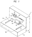
- Fig. 1 is a schematic perspective view showing a first embodiment of the present invention.
- a recording apparatus 1 comprises first and second frames 10, 20 which are rotatably connected to each other and in which parts of a recording mechanism are housed, and an automatic sheet supplying mechanism (automatic sheet supply means) 30 which permits the supply of a recording sheet (recording material) 100.
- the first frame 10 also serves as a sheet supply platform, and a pair of parallel side guides 11, 12 are formed on an upper surface 10a of the first frame.
- the side guides 11, 12 can be relatively shifted in a widthwise direction to set the recording sheet 100.
- the second frame 20 is connected to the first frame 10 via hinges 15 so that it can be rotated around the hinges 15 in directions shown by the arrow H within a range of 0 to 90 degrees.
- An ink jet head (recording means) 21 is housed in the second frame 20.
- the ink jet head 21 is designed so that bubbles are generated in the ink by utilizing the thermal energy, thereby forming ink droplets in response to a recording signal, which ink droplets are flying toward the recording sheet 100 to form an image on the recording sheet.
- the ink jet head 21 is mounted on a carriage 23 shifted along rails 22 in the widthwise direction of the recording sheet.
- a sheet convey mechanism for directing the recording sheet to the ink jet head 21 is formed in the second frame 20.
- the sheet convey mechanism comprises a convey roller 25, a guide 24 disposed along the convey roller 25, a pinch roller 26 urged against the convey roller 25 and adapted to pitch the recording sheet 100 between the rollers 25, 26 and feed out the recording sheet therefrom, and a pair of sheet discharge rollers 28, 29 for discharging the recording sheet 100 on which an image was formed by the ink jet head 21 through a sheet discharge opening 20b.
- the recording sheet 100 when the recording sheet 100 is manually inserted into the guide 24, the recording sheet 100 can be supplied between the ink jet head 21 and a platen 27 by the rotations of the convey roller 25 and the pinch roller 26.
- the automatic sheet supplying mechanism 30 capable of automatically supplying a plurality of recording sheets 100 between the ink jet head 21 and the platen 27.
- the automatic sheet supplying mechanism 30 has a feed-in portion 31 and a separation portion 35.
- the feed-in portion 31 comprises a friction plate (receiving portion) 32 supported by a spring 33 (a lower end of which is secured to the first frame 10) to be flush with the upper surface 10a of the sheet supply platform, and a feed-in roller (roller portion) 34 attached to the second frame 20 and having an equilateral triangular cross-section, which feed-in roller is rotated in a feed-in direction by a motor (not shown).
- the feed-in roller 34 is arranged in the proximity of a sheet supply opening 20a so that, when the second frame 20 is folded at an angle of 90 degrees (with respect to the first frame) as shown in Fig. 2, the feed-in roller is opposed to the friction plate 32 with a predetermined gap therebetween. In a condition that the recording sheet 100 is not set, when the feed-in roller 34 is rotated, it can be contacted with the friction plate 32 intermittently.
- the separation portion 35 comprises a friction plate (receiving portion) 36 supported by a spring 37 (a lower end of which is secured to the first frame 10) to be flush with the friction plate 32, and a separation roller (roller portion) 38 rotated in synchronous with the feed-in roller 34.
- the separation roller 38 is arranged rearwardly of the feed-in roller 34 so that, when the second frame 20 is folded at an angle of 90 degrees (with respect to the first frame) as shown in Fig. 2, the separation roller is contacted with the friction plate 36.
- the several recording sheets 100 fed from the feed-in portion 31 are separated one by one (from the uppermost one) by the separation portion 35, and the separated recording sheet is fed toward the guide 24.
- the recording apparatus 1 is operated in a condition that the second frame 20 is folded at the angle of 90 degrees with respect to the first frame 10.
- the recording sheets 100 are set in the feed-in portion 31 of the automatic sheet supplying mechanism 30. More specifically, in the condition that the motor is stopped, since the lower side of the feed-in roller 34 of the feed-in portion 31 is parallel with the friction plate 32 to create the gap therebetween, the plurality of recording sheets 100 are stacked on the upper surface 10a of the sheet supply platform and a leading end of the sheet stack is inserted into the gap.
- the separation roller 38 separates the uppermost recording sheet 100 from the other, and the separated recording sheet is pinched between the separation roller 38 and the friction plate 36 and then is sent to the guide 24. In this way, the automatic sheet supply is effected.
- the recording sheet 100 sent to the guide 24 is guided toward the pinch roller 26 by the guide 24 and then is pinched between the convey roller 25 and the pinch roller 26. In this point, the feed-in roller 34 of the feed-in portion 31 and the separation roller 38 of the separation portion 35 are stopped, and thereafter, the recording sheet 100 is sent between the ink jet head 21 and the platen 27 by the rotations of the convey roller 25 and the pinch roller 26.
- the convey roller 25 and the pinch roller 26 are stopped, and the carriage 23 is controlled by a motor (not shown) different from the above-mentioned motor. That is to say, the carriage 23 is reciprocally moved along the rail 22 by the discrete motor so that the image or character is recorded on the recording sheet 100 by the ink jet head 21 mounted on the carriage 23 in response to the recording signal.
- one-line recording main scan
- the ink jet head 21 is returned to its original position and the convey roller 25 and the pinch roller 26 are rotated to feed the recording sheet 100 toward the sheet discharge rollers 28, 29 by a predetermined amount.
- a next one-line recording is effected.
- the recording is effected on the whole area of the recording sheet 100.
- the recording sheet 100 is discharged out of the recording apparatus through the sheet discharge opening 20b by the rotation of the discharge rollers 28, 29.
- the above-mentioned sequence is repeated regarding the desired number of recording sheets 100 (to be recorded) supplied by the automatic sheet supplying mechanism 30. After the desired number of recording sheets are recorded, the recording apparatus is stopped.
- the recording apparatus 1 is made flat by rotating the second frame 20.
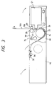
- the feed-in roller 34 and the separation roller 38 of the automatic sheet supplying mechanism 30 are separated from the friction plates 32, 36, respectively, thereby releasing the urging forces from the jammed recording sheet 100. Accordingly, in this condition, by pulling the recording sheet 100 in a direction shown by the arrow A, it is possible to easily remove the jammed recording sheet 100 from the recording apparatus 1.
- the whole recording apparatus 1 is made flat as a notebook by rotating the second frame 20, thereby making the accommodation of the apparatus easy.
- the recording apparatus 1 since the apparatus can assume two configurations and the automatic sheet supply and the jam treatment can be performed only by changing the configuration of the apparatus, the compactness of the apparatus and the improved recording efficiency can be achieved.
- Fig. 4 is a schematic sectional view showing a recording apparatus according to the second embodiment in its operative condition
- Fig. 5 is a schematic sectional view showing a condition that a recording sheet is to be set.
- the same constructural elements as those shown in the first embodiments are designated by the same reference numerals.
- the recording apparatus 40 according to this second embodiment differs from the recording apparatus of the first embodiment in the points that an automatic sheet supplying mechanism 50 is provided on the second frame 20 and the apparatus 40 can assume three configurations, i.e. an L-shaped configuration (Fig. 4), a flat configuration (not shown), and a third configuration as shown in Fig. 5.
- an automatic sheet supplying mechanism 50 is provided on the second frame 20 and the apparatus 40 can assume three configurations, i.e. an L-shaped configuration (Fig. 4), a flat configuration (not shown), and a third configuration as shown in Fig. 5.
- the automatic sheet supplying mechanism 50 comprises a friction plate (receiving portion) 51 rotatably mounted on a front end of the guide 24, and a feed-in roller 54 and a separation roller 55 as a roller portion.
- the friction plate 51 is rotatably attached to the second frame via a pin 52 at its base end and is biased upwardly by a leaf spring 53 attached to the first frame 10.
- the pin 52 supporting the friction plate 51 has appropriate play with respect to the guide 24, so that the friction plate 51 biased by the leaf spring 53 can be urged against both of the feed-in roller 54 and the separation roller 55.
- the feed-in roller 54 is disposed in the proximity of the sheet supply opening 20a formed in the second frame 20a, and the separation roller 55 is arranged rearwardly of the feed-in roller 54.
- the second frame 20 including such sheet supplying mechanism 50 is rotatably connected to the first frame 10 so that it can assume not only the L-shaped configuration (the second frame is folded at an angle of 90 degrees with respect to the first frame) and the flat configuration but also an angled configuration (third configuration) in which the feed-in roller 54 and the separation roller 55 are slightly separated from the friction plate 51 as shown in Fig. 5.
- the second frame 20 is slightly inclined from the L-shaped configuration as shown in Fig. 4 to the third configuration as shown in Fig. 5.
- the feed-in roller 54 and the separation roller 55 are slightly separated from the friction plate 51 to create a gap therebetween, a plurality of recording sheets 100 are inserted below the feed-in roller 54.
- the second frame 20 is returned to the L-shaped configuration as shown in Fig. 4, the plurality of recording sheets 100 are pinched between the feed-in roller 54 and the friction plate 51, thereby completing the setting of the recording sheets 100.
- the second frame 20 is slightly inclined again to assume the third configuration, thereby releasing the urging force of the feed-in roller 54 and the separation roller 55 from the jammed recording sheet 100. As a result, it is possible to easily remove the jammed recording sheet 100 from the apparatus 40.
- the second frame 20 is rotated to make the apparatus 40 flat, thereby achieving the easy accommodation of the recording apparatus 40.
- the contact areas between the friction plate 51 and the rollers are not exposed outwardly, the contact areas is prevented from advertently smudging, with the result that the double-feed of the recording sheets and the poor feeding of the recording sheet due to the contamination of the contact areas can be prevented.
- the first configuration or L-shaped configuration which is stable in the operative condition the second configuration or flat configuration which permits the easy accommodation of the apparatus, and the third configuration in which the urging forces of the feed-in roller 54 and the separation roller 55 are released to permit the setting of the recording sheets and the jam treatment can be assumed.
- the whole recording apparatus can be made small-sized, and, since the automatic sheet supplying mechanism in synchronous with the movement of the frame is provided, a plurality of recording sheets can be successively supplied automatically, and further, the jam treatment can easily be effected only by rotating the frame.
- the sheet supplying apparatus of the present invention can also be applied to a sheet treatment apparatus wherein a sheet is perforated and/or folded.
- Fig. 6 is a sectional view showing an accommodation condition of a recording apparatus
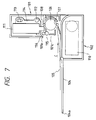
- Fig. 7 is a sectional view showing an operative condition of the recording apparatus.
- the recording apparatus comprises frames 101, 102 pivotally connected to each other via a fulcrum 103. These frames form a constructural member.
- a cover member 104 is normally rested on one surface of the frame 102 and is pivotally connected to one end of the frame 102.
- a protruded portion 104a formed on a free end of the cover member 104 is normally engaged by a recessed portion 101a formed in one end of the frame 101.
- the protruded portion 104a of the cover member 104 is disengaged from the recessed portion 101a of the frame 101 and then the cover member is fully opened. Then, the frame 101 is rotated around the fulcrum 103 to establish a condition as shown in Fig. 7.
- the recording sheet 105 When a recording sheet 105 is rested on the cover member 104 opened as shown in Fig. 7 and is inserted toward a direction shown by the arrow C, the recording sheet 105 is pulled between a convey roller 106 and a pinch roller 107 by the rotation of the convey roller 106, thereby feeding the recording sheet.
- the recording sheet 105 reaches below a recording head 111, the recording is started in response to a recording signal inputted to an electric portion 110.
- the recording head 111 is mounted on a carriage 114 supported by rails 112, 113 so that one-line of an image can be recorded on the recording sheet as the carriage 114 is shifted. Whenever the recording of the one-line is finished, the recording sheet 105 is line-spaced by the roller 106. By repeating such operations, the recording sheet is ultimately discharged on the cover member 104 by discharge rollers 115, 116.
- the cover member 104 of the recording apparatus has a locking function for preventing the relative rotation between the frames 101, 102 around the fulcrum 103 during the accommodation or transportation, a tray function for supporting the recording sheet during the sheet supply and sheet discharge, and a cover function for covering an opening 101C of the frame 101, thereby preventing any play between the two frames of the recording apparatus during the accommodation and transportion of the recording apparatus.
- Fig. 8 is a perspective view of a recording apparatus according to a fourth embodiment of the present invention in its accommodation condition. Since this fourth embodiment is fundamentally the same as the above-mentioned third embodiment, only the difference will be described.
- a cover member 120 is pivotally connected to the frame 102 via a fulcrum 121 for rotational movement in directions shown by the arrow D.
- the frame 101 is cocked in a direction shown by the arrow E from a condition shown in Fig. 8, an operative condition of the recording apparatus is established.
- the cover member 120 serves as a tray.
- the frame 101 is laid again and the cover member 120 is rotated in the direction D to cover or conceal the discharge rollers 115, 116, a locking condition for preventing the rotation of the frame 101 in the direction E can be established.
- Fig. 9 is a perspective view of a recording apparatus according to a fifth embodiment of the present invention in its accommodation condition. Since this fifth embodiment is fundamentally the same as the above-mentioned third embodiment, only the difference will be described.
- a pair of opposed hook-shaped guide portions 131 are formed on one surface of the frame 102, and a cover member 130 is received between the guide portions 131 for sliding movement in directions shown by the arrow F.
- the cover member 130 serves as a tray.
- the same technical effect as that of the third embodiment can be achieved, and since the sliding amount of the cover member 130 can be adjusted appropriately, the recording apparatus can be installed in a narrower space.
- the cover member is provided on the constructural member comprising two molded pieces rotatably connected to each other, and the cover member serves to prevent the relative rotation of the two molded pieces during the accommodation and transportation and also serves as a tray when the cover member is opened in the operative condition.
- the recording apparatus can assume the stable L-shaped configuration in its operative condition which permits the recording. In the accommodation condition, the portable configuration having no play can be established.
- the cover member may cover the sheet convey rollers, separation members, operation switches and connector members, as well as the inlet and outlet of the sheet conveying path.
- the present invention provides a sheet supplying apparatus comprising first and second boxes shiftable relative to each other, a sheet receiving portion provided on the first box for receiving a sheet, and a rotary member provided on the second box for cooperating with the sheet receiving portion to thereby pinch and supply the sheet when a relative position between the first and second boxes is in a first condition and separated from the sheet receiving portion when the relative position between the first and second boxes is in a second condition.
Abstract
Description
- The present invention relates a sheet supplying apparatus applied to a recording apparatus for recording a character or an image on a recording material.
- A conventional recording apparatus including a sheet supplying apparatus and having a printing, copying or facsimile function, or a conventional recording apparatus used as an output means for a copying machine or work station including a computer or a word processor is designed so that an image (including characters and/or symbols) is recorded on a recording medium such as a paper sheet or a plastic thin film (for example, an OHP sheet) on the basis of a data signal. Such recording apparatuses can be grouped into an ink jet type, a wire dot type, a heat-sensitive type, a heat transfer type and a laser beam type, in dependence upon recording types.
- In a recording apparatus of serial type wherein a main scan is effected along a direction transverse to a feeding direction (sub scan direction) of a recording material, after the recording material is set at a predetermined recording position, an image is recorded (main scan) on the recording material by a recording means (recording head) mounted on a carriage shifted along the recording material. After one-line recording is finished, the recording material is line-spaced (sub scan) by a predetermined amount. Thereafter, by repeating the recording (main scan) of the next line of the image, the whole image is recorded on the recording material.
- On the other hand, in a recording apparatus of line type wherein an image is recorded on a recording material only by the sub scan which is effected along a feeding direction of the recording material, after the recording material is set at a predetermined recording position and then one-line recording is effected collectively, the recording material is fed (pitch feed) by a predetermined amount. Then, by repeating the collective recording of the next line of the image, the whole image is recorded on the recording material.
- Among these recording apparatuses, a recording apparatus of ink jet type (ink jet recording apparatus) is so designed that the recording is effected by discharging ink droplets from discharge openings of a recording means (recording head) toward a recording material in response to a data signal. Thus, in this apparatus, the recording means can easily be made compact and the fine image can be recorded at a high speed. Further, since the image can be recorded on a normal sheet without the special treatment, it is possible to reduce the running cost. Furthermore, due to the non-impact recording type, the recording noise can be reduced, and a color image can easily be recorded by using inks of different color.
- Particularly, in a recording means (recording head) of ink jet type wherein ink is discharged by utilizing thermal energy, since the high density liquid passage arrangement (discharge opening arrangement) can easily be attained by forming electro-thermal converters and electrodes deposited on a substrate, liquid passage walls, top wall and the like by semi-conductor manufacture process such as etching, depositing and spattering, it is possible to make the recording means further compact.
- By the way, recently, host computers such as personal computers have been made small-sized, and notebook-shaped computers having A4 size have been widely popularized. Correspondingly, small-sized recording apparatuses as output means have also been developed to provide a notebook-type and an elongate parallelpiped type which are portable and can be accommodated in a drawer of a desk.
- However, as the recording apparatus is made small-sized to provide the portability and the easy accommodation ability, the optimum configuration of the recording apparatus in its operative condition greatly differs from the optimum configuration of the recording apparatus in its inoperative condition. That is to say, if the configuration of the recording apparatus is permanently made small-sized to obtain the best configuration in its operative condition, the configuration in its inoperative condition will become unsuitable; whereas, if the configuration of the recording apparatus in its inoperative condition is made optimum, the configuration in its operative condition will become unsuitable.
- To avoid this, as disclosed in the Japanese Patent Laid-open No. 5-124301 (USSN 968,327), there has been proposed a recording apparatus which is of foldable type to assume two configurations so that both the optimum configuration in its operative condition and the optimum configuration in its inoperative condition can be obtained.
- However, an automatic sheet supplying apparatus and/or a jam treatment apparatus cannot be incorporated into this recording apparatus, because, if the automatic sheet supplying apparatus or the jam treatment apparatus is incorporated into this recording apparatus, the whole recording apparatus will be large-sized, which is contrary to the expected purpose for making the apparatus compact. Accordingly, in this recording apparatus, there arose problems that the sheet supplying operation is troublesome and that the recording efficiency is worsened.
- Further, in the conventional recording apparatuses, although the stability in the operative condition and the downward recording ability were preserved, there arose a problem that it is difficult to handle the apparatus in the accommodation condition or the portable condition because of the presence of the play in hinge portions.
- The present invention aims to eliminate the above-mentioned conventional drawbacks, and has an object to provide a sheet supplying apparatus which is suitable to be applied to an image recording apparatus and which can satisfy the compactness of the recording apparatus and stabilize the recording apparatus in its accommodation condition and in its portable condition.
- Another object of the present invention is to provide a recording apparatus which is made small-sized and which includes an automatic sheet supply means and a jam treatment means.
- To achieve the above objects, according to one aspect of the present invention, there is provided a sheet supplying apparatus used with a recording apparatus wherein a recording means for recording an image on a recording material is arranged on one of first and second frames which are rotatably connected to each other. The sheet supplying apparatus comprises an automatic sheet supply means including a receiving portion for receiving a supplied recording material and a roller portion rotatable in a supplying direction of the recording material. Wherein one of the roller portion and the receiving portion is moved toward and away with respect to the other of these portions in synchronous with the rotation of the first or second frame.
- Another aspect of the present invention, there is provided a sheet supplying apparatus used with a recording apparatus including an integral constructural member comprising two molded pieces connected to each other for rotational movements around a common axis at their one ends, and a cover member adapted to be shiftably engaged by one surface of the constructural member. Wherein the cover member is attached to the constructural member to provide a rotation preventing means and a recording material receiving tray mechanism.
-
- Fig. 1 is a schematic perspective view of a recording apparatus using a sheet supplying apparatus according to a first embodiment of the present invention;
- Fig. 2 is a schematic sectional view of the recording apparatus of Fig. 1 in its operative condition;
- Fig. 3 is a schematic sectional view of the recording apparatus of Fig. 1 in its inoperative condition;
- Fig. 4 is a schematic sectional view of a recording apparatus using a sheet supplying apparatus according to a second embodiment of the present invention, in its operative condition;
- Fig. 5 is a schematic sectional view of the recording apparatus of Fig. 4 showing a condition that recording sheets are set and the jammed condition;
- Fig. 6 is a sectional view of a recording apparatus using a sheet supplying apparatus according to a third embodiment of the present invention, in its accommodation condition;
- Fig. 7 is a schematic sectional view of the recording apparatus of Fig. 6 in its operative condition;
- Fig. 8 is a perspective view of a recording apparatus using a sheet supplying apparatus according to a fourth embodiment of the present invention, in its accommodation condition; and
- Fig. 9 is a perspective view of a recording apparatus using a sheet supplying apparatus according to a fifth embodiment of the present invention, in its accommodation condition.
- The present invention will now be explained in connection with embodiments thereof with reference to the accompanying drawings.
- Fig. 1 is a schematic perspective view showing a first embodiment of the present invention.
- A
recording apparatus 1 according to the first embodiment comprises first andsecond frames - The
first frame 10 also serves as a sheet supply platform, and a pair ofparallel side guides upper surface 10a of the first frame. Theside guides recording sheet 100. - On the other hand, as shown in Fig. 2, the
second frame 20 is connected to thefirst frame 10 viahinges 15 so that it can be rotated around thehinges 15 in directions shown by the arrow H within a range of 0 to 90 degrees. An ink jet head (recording means) 21 is housed in thesecond frame 20. - The
ink jet head 21 is designed so that bubbles are generated in the ink by utilizing the thermal energy, thereby forming ink droplets in response to a recording signal, which ink droplets are flying toward therecording sheet 100 to form an image on the recording sheet. Theink jet head 21 is mounted on acarriage 23 shifted alongrails 22 in the widthwise direction of the recording sheet. - A sheet convey mechanism for directing the recording sheet to the
ink jet head 21 is formed in thesecond frame 20. The sheet convey mechanism comprises aconvey roller 25, aguide 24 disposed along theconvey roller 25, apinch roller 26 urged against theconvey roller 25 and adapted to pitch therecording sheet 100 between therollers sheet discharge rollers recording sheet 100 on which an image was formed by theink jet head 21 through a sheet discharge opening 20b. - Accordingly, when the
recording sheet 100 is manually inserted into theguide 24, therecording sheet 100 can be supplied between theink jet head 21 and aplaten 27 by the rotations of theconvey roller 25 and thepinch roller 26. In therecording apparatus 1 according to the illustrated embodiment, there is provided the automaticsheet supplying mechanism 30 capable of automatically supplying a plurality ofrecording sheets 100 between theink jet head 21 and theplaten 27. - The automatic
sheet supplying mechanism 30 has a feed-inportion 31 and aseparation portion 35. The feed-inportion 31 comprises a friction plate (receiving portion) 32 supported by a spring 33 (a lower end of which is secured to the first frame 10) to be flush with theupper surface 10a of the sheet supply platform, and a feed-in roller (roller portion) 34 attached to thesecond frame 20 and having an equilateral triangular cross-section, which feed-in roller is rotated in a feed-in direction by a motor (not shown). - The feed-in
roller 34 is arranged in the proximity of a sheet supply opening 20a so that, when thesecond frame 20 is folded at an angle of 90 degrees (with respect to the first frame) as shown in Fig. 2, the feed-in roller is opposed to thefriction plate 32 with a predetermined gap therebetween. In a condition that therecording sheet 100 is not set, when the feed-inroller 34 is rotated, it can be contacted with thefriction plate 32 intermittently. Thus, when a plurality ofrecording sheets 100 are set between thefriction plate 32 and the feed-in roller 34 (in a condition that one lateral side of the triangle of the feed-in roller is parallel with the friction plate 32) and then the feed-inroller 34 is rotated, severalupper recording sheets 100 are fed out toward theseparation portion 35 by apexes of the triangle of the feed-inroller 34. - The
separation portion 35 comprises a friction plate (receiving portion) 36 supported by a spring 37 (a lower end of which is secured to the first frame 10) to be flush with thefriction plate 32, and a separation roller (roller portion) 38 rotated in synchronous with the feed-inroller 34. - The
separation roller 38 is arranged rearwardly of the feed-inroller 34 so that, when thesecond frame 20 is folded at an angle of 90 degrees (with respect to the first frame) as shown in Fig. 2, the separation roller is contacted with thefriction plate 36. Thus, theseveral recording sheets 100 fed from the feed-inportion 31 are separated one by one (from the uppermost one) by theseparation portion 35, and the separated recording sheet is fed toward theguide 24. - Next, an operation of the recording apparatus according to the illustrated embodiment will be explained.
- First of all, the operation of the
recording apparatus 1 in its operative condition will be described with reference to Figs. 1 and 2. - As shown in Figs. 1 and 2, the
recording apparatus 1 is operated in a condition that thesecond frame 20 is folded at the angle of 90 degrees with respect to thefirst frame 10. - First of all, in a condition that the motor is stopped, the
recording sheets 100 are set in the feed-inportion 31 of the automaticsheet supplying mechanism 30. More specifically, in the condition that the motor is stopped, since the lower side of the feed-inroller 34 of the feed-inportion 31 is parallel with thefriction plate 32 to create the gap therebetween, the plurality ofrecording sheets 100 are stacked on theupper surface 10a of the sheet supply platform and a leading end of the sheet stack is inserted into the gap. - Then, when a predetermined recording signal is sent from a computer (not shown), the motor is operated to rotate the feed-in
roller 34 in a recording sheet feeding direction (anti-clockwise direction in Fig. 2). As a result, severalupper recording sheets 100 are fed into theseparation portion 35. - In the
separation portion 35, theseparation roller 38 separates theuppermost recording sheet 100 from the other, and the separated recording sheet is pinched between theseparation roller 38 and thefriction plate 36 and then is sent to theguide 24. In this way, the automatic sheet supply is effected. - The
recording sheet 100 sent to theguide 24 is guided toward thepinch roller 26 by theguide 24 and then is pinched between the conveyroller 25 and thepinch roller 26. In this point, the feed-inroller 34 of the feed-inportion 31 and theseparation roller 38 of theseparation portion 35 are stopped, and thereafter, therecording sheet 100 is sent between theink jet head 21 and theplaten 27 by the rotations of the conveyroller 25 and thepinch roller 26. - When a leading end of the
recording sheet 100 reaches a predetermined position on theplaten 27, the conveyroller 25 and thepinch roller 26 are stopped, and thecarriage 23 is controlled by a motor (not shown) different from the above-mentioned motor. That is to say, thecarriage 23 is reciprocally moved along therail 22 by the discrete motor so that the image or character is recorded on therecording sheet 100 by theink jet head 21 mounted on thecarriage 23 in response to the recording signal. - More specifically, when the
ink jet head 21 is shifted in the widthwise direction of the recording sheet, one-line recording (main scan) is effected. When the one-line recording is finished, theink jet head 21 is returned to its original position and the conveyroller 25 and thepinch roller 26 are rotated to feed therecording sheet 100 toward thesheet discharge rollers recording sheet 100. After the recording is completed, therecording sheet 100 is discharged out of the recording apparatus through thesheet discharge opening 20b by the rotation of thedischarge rollers sheet supplying mechanism 30. After the desired number of recording sheets are recorded, the recording apparatus is stopped. - Next, the jam treatment condition and the configuration of the recording apparatus in the inoperative condition will be explained with reference to Fig. 3.
- If the
recording sheet 100 is jammed during the recording operation, as shown in Fig. 3, therecording apparatus 1 is made flat by rotating thesecond frame 20. As a result, the feed-inroller 34 and theseparation roller 38 of the automaticsheet supplying mechanism 30 are separated from thefriction plates recording sheet 100. Accordingly, in this condition, by pulling therecording sheet 100 in a direction shown by the arrow A, it is possible to easily remove the jammedrecording sheet 100 from therecording apparatus 1. - Further, when the
recording apparatus 1 is not used, thewhole recording apparatus 1 is made flat as a notebook by rotating thesecond frame 20, thereby making the accommodation of the apparatus easy. - In this way, in the
recording apparatus 1 according to the illustrated embodiment, since the apparatus can assume two configurations and the automatic sheet supply and the jam treatment can be performed only by changing the configuration of the apparatus, the compactness of the apparatus and the improved recording efficiency can be achieved. - Incidentally, various alterations can be effected within the scope of the present invention. For example, while the
friction plates friction plates recording sheet 100. Further, while an example that the feed-inroller 34 has the triangular cross-section was explained, the present invention is not limited to this example, but it should be noted that the feed-in roller has any desired polygonal cross-section. - Next, a second embodiment of the present invention will be explained with reference to Figs. 4 and 5.
- Fig. 4 is a schematic sectional view showing a recording apparatus according to the second embodiment in its operative condition, and Fig. 5 is a schematic sectional view showing a condition that a recording sheet is to be set. Incidentally, the same constructural elements as those shown in the first embodiments are designated by the same reference numerals.
- The
recording apparatus 40 according to this second embodiment differs from the recording apparatus of the first embodiment in the points that an automaticsheet supplying mechanism 50 is provided on thesecond frame 20 and theapparatus 40 can assume three configurations, i.e. an L-shaped configuration (Fig. 4), a flat configuration (not shown), and a third configuration as shown in Fig. 5. - The automatic
sheet supplying mechanism 50 comprises a friction plate (receiving portion) 51 rotatably mounted on a front end of theguide 24, and a feed-inroller 54 and aseparation roller 55 as a roller portion. Thefriction plate 51 is rotatably attached to the second frame via apin 52 at its base end and is biased upwardly by aleaf spring 53 attached to thefirst frame 10. Thepin 52 supporting thefriction plate 51 has appropriate play with respect to theguide 24, so that thefriction plate 51 biased by theleaf spring 53 can be urged against both of the feed-inroller 54 and theseparation roller 55. On the other hand, the feed-inroller 54 is disposed in the proximity of thesheet supply opening 20a formed in thesecond frame 20a, and theseparation roller 55 is arranged rearwardly of the feed-inroller 54. - The
second frame 20 including suchsheet supplying mechanism 50 is rotatably connected to thefirst frame 10 so that it can assume not only the L-shaped configuration (the second frame is folded at an angle of 90 degrees with respect to the first frame) and the flat configuration but also an angled configuration (third configuration) in which the feed-inroller 54 and theseparation roller 55 are slightly separated from thefriction plate 51 as shown in Fig. 5. - Accordingly, in the operative condition of the
recording apparatus 40, thesecond frame 20 is slightly inclined from the L-shaped configuration as shown in Fig. 4 to the third configuration as shown in Fig. 5. In this condition, since the feed-inroller 54 and theseparation roller 55 are slightly separated from thefriction plate 51 to create a gap therebetween, a plurality ofrecording sheets 100 are inserted below the feed-inroller 54. Then, when thesecond frame 20 is returned to the L-shaped configuration as shown in Fig. 4, the plurality ofrecording sheets 100 are pinched between the feed-inroller 54 and thefriction plate 51, thereby completing the setting of therecording sheets 100. - Thereafter, the automatic sheet supplying operation is effected in the same manner as the first embodiment.
- On the other hand, if the recording sheet is jammed, the
second frame 20 is slightly inclined again to assume the third configuration, thereby releasing the urging force of the feed-inroller 54 and theseparation roller 55 from the jammedrecording sheet 100. As a result, it is possible to easily remove the jammedrecording sheet 100 from theapparatus 40. - Further, in the inoperative condition of the
recording apparatus 40, thesecond frame 20 is rotated to make theapparatus 40 flat, thereby achieving the easy accommodation of therecording apparatus 40. In this flat configuration, since the contact areas between thefriction plate 51 and the rollers are not exposed outwardly, the contact areas is prevented from advertently smudging, with the result that the double-feed of the recording sheets and the poor feeding of the recording sheet due to the contamination of the contact areas can be prevented. - In conclusion, in the
recording apparatus 40 according to the second embodiment, the first configuration or L-shaped configuration which is stable in the operative condition, the second configuration or flat configuration which permits the easy accommodation of the apparatus, and the third configuration in which the urging forces of the feed-inroller 54 and theseparation roller 55 are released to permit the setting of the recording sheets and the jam treatment can be assumed. - With the arrangement as mentioned above, according to the second embodiment of the present invention, the whole recording apparatus can be made small-sized, and, since the automatic sheet supplying mechanism in synchronous with the movement of the frame is provided, a plurality of recording sheets can be successively supplied automatically, and further, the jam treatment can easily be effected only by rotating the frame.
- Incidentally, the sheet supplying apparatus of the present invention can also be applied to a sheet treatment apparatus wherein a sheet is perforated and/or folded.
- Next, a third embodiment of the present invention will be explained with reference to Figs. 6 and 7. Fig. 6 is a sectional view showing an accommodation condition of a recording apparatus, and Fig. 7 is a sectional view showing an operative condition of the recording apparatus.
- In Fig. 6, the recording apparatus according to the third embodiment comprises
frames fulcrum 103. These frames form a constructural member. Acover member 104 is normally rested on one surface of theframe 102 and is pivotally connected to one end of theframe 102. A protrudedportion 104a formed on a free end of thecover member 104 is normally engaged by a recessedportion 101a formed in one end of theframe 101. - In a condition shown in Fig. 6, i.e. in an accommodation and portable condition, even if the user tries to rotate the
frame 102 in a direction shown by the arrow A, aportion 102b of theframe 102 is blocked by aportion 101b of theframe 101, thereby preventing the rotation of theframe 102. On the other hand, even if the user tries to rotate theframe 102 in a direction shown by the arrow B, thecover member 104 is blocked by theframe 101, thereby preventing the rotation of theframe 102. Accordingly, during the transportation of the recording apparatus, the unstable condition of the recording apparatus can be avoided. On the other hand, in an operative condition shown in Fig. 7, the protrudedportion 104a of thecover member 104 is disengaged from the recessedportion 101a of theframe 101 and then the cover member is fully opened. Then, theframe 101 is rotated around thefulcrum 103 to establish a condition as shown in Fig. 7. - Now, the actual recording operation will be explained with reference to Fig. 7.
- When a
recording sheet 105 is rested on thecover member 104 opened as shown in Fig. 7 and is inserted toward a direction shown by the arrow C, therecording sheet 105 is pulled between a conveyroller 106 and apinch roller 107 by the rotation of the conveyroller 106, thereby feeding the recording sheet. When therecording sheet 105 reaches below arecording head 111, the recording is started in response to a recording signal inputted to anelectric portion 110. Therecording head 111 is mounted on acarriage 114 supported byrails carriage 114 is shifted. Whenever the recording of the one-line is finished, therecording sheet 105 is line-spaced by theroller 106. By repeating such operations, the recording sheet is ultimately discharged on thecover member 104 bydischarge rollers - In this way, the
cover member 104 of the recording apparatus according to the third embodiment has a locking function for preventing the relative rotation between theframes fulcrum 103 during the accommodation or transportation, a tray function for supporting the recording sheet during the sheet supply and sheet discharge, and a cover function for covering an opening 101C of theframe 101, thereby preventing any play between the two frames of the recording apparatus during the accommodation and transportion of the recording apparatus. - Next, a fourth embodiment of the present invention will be explained with reference to Fig. 8.
- Fig. 8 is a perspective view of a recording apparatus according to a fourth embodiment of the present invention in its accommodation condition. Since this fourth embodiment is fundamentally the same as the above-mentioned third embodiment, only the difference will be described.
- In this fourth embodiment, a
cover member 120 is pivotally connected to theframe 102 via afulcrum 121 for rotational movement in directions shown by the arrow D. When theframe 101 is cocked in a direction shown by the arrow E from a condition shown in Fig. 8, an operative condition of the recording apparatus is established. In this condition, thecover member 120 serves as a tray. When theframe 101 is laid again and thecover member 120 is rotated in the direction D to cover or conceal thedischarge rollers frame 101 in the direction E can be established. - Thus, the same technical effect as that of the third embodiment can be achieved. Lastly, a fifth embodiment of the present invention will be explained with reference to Fig. 9.
- Fig. 9 is a perspective view of a recording apparatus according to a fifth embodiment of the present invention in its accommodation condition. Since this fifth embodiment is fundamentally the same as the above-mentioned third embodiment, only the difference will be described.
- In this fifth embodiment, a pair of opposed hook-shaped
guide portions 131 are formed on one surface of theframe 102, and acover member 130 is received between theguide portions 131 for sliding movement in directions shown by the arrow F. When theframe 101 is cocked in a direction shown by the arrow G from a condition shown in Fig. 9, an operative condition of the recording apparatus is established. In this condition, thecover member 130 serves as a tray. When theframe 101 is laid again and thecover member 130 is slid in the direction F to cover or conceal thedischarge rollers frame 101 in the direction G can be established. - Thus, the same technical effect as that of the third embodiment can be achieved, and since the sliding amount of the
cover member 130 can be adjusted appropriately, the recording apparatus can be installed in a narrower space. - According to this embodiment, the cover member is provided on the constructural member comprising two molded pieces rotatably connected to each other, and the cover member serves to prevent the relative rotation of the two molded pieces during the accommodation and transportation and also serves as a tray when the cover member is opened in the operative condition. Thus, the recording apparatus can assume the stable L-shaped configuration in its operative condition which permits the recording. In the accommodation condition, the portable configuration having no play can be established.
- Incidentally, the cover member may cover the sheet convey rollers, separation members, operation switches and connector members, as well as the inlet and outlet of the sheet conveying path.
- The present invention provides a sheet supplying apparatus comprising first and second boxes shiftable relative to each other, a sheet receiving portion provided on the first box for receiving a sheet, and a rotary member provided on the second box for cooperating with the sheet receiving portion to thereby pinch and supply the sheet when a relative position between the first and second boxes is in a first condition and separated from the sheet receiving portion when the relative position between the first and second boxes is in a second condition.
Claims (23)
- A sheet supplying apparatus, comprising:
first and second boxes shiftable relative to each other;
a sheet receiving portion provided on said first box for receiving a sheet; and
a rotary member provided on said second box for cooperating with said sheet receiving portion to thereby pinch and supply the sheet when a relative position between said first and second boxes is in a first condition and separated from said sheet receiving portion when the relative position between said first and second boxes is in a second condition. - A sheet supplying apparatus according to claim 1, wherein said first and second boxes are rotatably connected to each other.
- A sheet supplying apparatus according to claim 2, wherein said sheet receiving portion and said rotary member are moved toward and away from each other in response to the rotation of said first or second box.
- A sheet supplying apparatus according to claim 1, wherein, in said first condition, said first and second boxes are substantially perpendicular to each other.
- A sheet supplying apparatus according to claim 4, wherein, in said second condition, said first and second boxes become flat each other.
- A sheet supplying apparatus according to claim 5, wherein said first and second boxes assume a third condition where they form an angle between said first and second conditions and said rotary member is separated from said sheet receiving portion.
- A sheet supplying apparatus according to claim 1, wherein said sheet receiving portion includes a friction plate, and said rotary member includes a roller.
- A sheet supplying apparatus according to claim 7, wherein, when said first and second boxes are in said first condition, said friction plate and said roller cooperate with each other to separate a single sheet from a plurality of stacked sheets.
- A sheet supplying apparatus according to claim 1, further comprising recording means for recording an image on the sheet supplied by said rotary member.
- A sheet supplying apparatus according to claim 9, wherein said recording means forms an ink droplet by utilizing thermal energy and records the image on the sheet by utilizing the formed ink droplet.
- A recording apparatus, comprising:
first and second boxes shiftable relative to each other;
a sheet receiving portion provided on said first box for receiving a sheet;
a rotary member provided on said second box for cooperating with said sheet receiving portion to thereby pinch and supply the sheet when a relative position between said first and second boxes is in a first condition and separated from said sheet receiving portion when the relative position between said first and second boxes is in a second condition; and
recording means for recording an image on the sheet supplied by said rotary member. - A recording apparatus according to claim 11, wherein said recording means forms an ink droplet by utilizing thermal energy and records the image on the sheet by utilizing the formed ink droplet.
- A sheet suppling apparatus, comprising:
first and second boxes shiftable relative to each other;
sheet supply means provided on said first frame for supplying a sheet; and
a cover for covering at least a portion of said first or second box when a relative position between said first and second boxes is in a predetermined condition. - A sheet supplying apparatus according to claim 13, wherein said first and second boxes are rotatably connected to each other.
- A sheet supplying apparatus according to claim 13, wherein, in said predetermined condition, said first and second boxes become flat each other.
- A sheet supplying apparatus according to claim 13, wherein said sheet supply means permits the supply of the sheet when said first and second boxes are moved to be substantially perpendicular to each other.
- A sheet supplying apparatus according to claim 13, wherein said cover can serve as a tray on which the sheet is rested.
- A sheet supplying apparatus according to claim 13, wherein said cover can cover said sheet supply means.
- A sheet supplying apparatus according to claim 13, wherein said cover can cover an operation switch provided on said first or second frame.
- A sheet supplying apparatus according to claim 13, wherein said cover can maintain a relative position between said first and second boxes in said predetermined condition.
- A sheet supplying apparatus according to claim 13, wherein said cover can cover a connector provided on said first or second box.
- A sheet supplying apparatus according to claim 13, further comprising recording means for recording an image on the sheet supplied by said sheet supply means.
- A sheet supplying apparatus according to claim 13, wherein said recording means forms an ink droplet by utilizing thermal energy and records the image on the sheet by utilizing the formed ink droplet.
Applications Claiming Priority (4)
| Application Number | Priority Date | Filing Date | Title |
|---|---|---|---|
| JP4260267A JP2974516B2 (en) | 1992-09-29 | 1992-09-29 | Image recording device |
| JP260267/92 | 1992-09-29 | ||
| JP4357716A JP2915231B2 (en) | 1992-12-25 | 1992-12-25 | Recording device |
| JP357716/92 | 1992-12-25 |
Publications (3)
| Publication Number | Publication Date |
|---|---|
| EP0590585A2 true EP0590585A2 (en) | 1994-04-06 |
| EP0590585A3 EP0590585A3 (en) | 1995-09-06 |
| EP0590585B1 EP0590585B1 (en) | 1999-06-02 |
Family
ID=26544532
Family Applications (1)
| Application Number | Title | Priority Date | Filing Date |
|---|---|---|---|
| EP93115613A Expired - Lifetime EP0590585B1 (en) | 1992-09-29 | 1993-09-28 | Sheet supplying apparatus |
Country Status (5)
| Country | Link |
|---|---|
| US (1) | US5538237A (en) |
| EP (1) | EP0590585B1 (en) |
| KR (1) | KR0151175B1 (en) |
| AT (1) | ATE180719T1 (en) |
| DE (1) | DE69325136T2 (en) |
Families Citing this family (7)
| Publication number | Priority date | Publication date | Assignee | Title |
|---|---|---|---|---|
| US6382858B1 (en) * | 1997-11-14 | 2002-05-07 | Canon Kabushiki Kaisha | Sheet material conveying apparatus and recording apparatus |
| IT1304988B1 (en) * | 1998-09-14 | 2001-04-05 | Olivetti Lexikon Spa | PRINTER OPERABLE IN TWO POSITIONS. |
| US7021755B2 (en) * | 2002-09-30 | 2006-04-04 | Canon Kabushiki Kaisha | Printing apparatus |
| US7172354B1 (en) * | 2004-12-09 | 2007-02-06 | Y. Nissim, Inc. | Self-contained edge printer |
| US20070188818A1 (en) * | 2006-02-13 | 2007-08-16 | Eastman Kodak Company | Tiltable document imaging apparatus |
| TWD166688S (en) * | 2014-03-10 | 2015-03-21 | 虹光精密工業股份有限公司 | Scanner |
| JP6842341B2 (en) | 2017-03-30 | 2021-03-17 | 富士通コンポーネント株式会社 | Electronic device |
Citations (1)
| Publication number | Priority date | Publication date | Assignee | Title |
|---|---|---|---|---|
| WO1990013433A1 (en) * | 1989-04-28 | 1990-11-15 | Siemens Aktiengesellschaft | Image printing device |
Family Cites Families (19)
| Publication number | Priority date | Publication date | Assignee | Title |
|---|---|---|---|---|
| US3827687A (en) * | 1971-04-21 | 1974-08-06 | Minolta Camera Kk | Device for supporting sensitive paper cassette for electrophotography copier |
| CA1127227A (en) * | 1977-10-03 | 1982-07-06 | Ichiro Endo | Liquid jet recording process and apparatus therefor |
| JPS5936879B2 (en) * | 1977-10-14 | 1984-09-06 | キヤノン株式会社 | Thermal transfer recording medium |
| US4330787A (en) * | 1978-10-31 | 1982-05-18 | Canon Kabushiki Kaisha | Liquid jet recording device |
| US4345262A (en) * | 1979-02-19 | 1982-08-17 | Canon Kabushiki Kaisha | Ink jet recording method |
| US4463359A (en) * | 1979-04-02 | 1984-07-31 | Canon Kabushiki Kaisha | Droplet generating method and apparatus thereof |
| US4313124A (en) * | 1979-05-18 | 1982-01-26 | Canon Kabushiki Kaisha | Liquid jet recording process and liquid jet recording head |
| US4558333A (en) * | 1981-07-09 | 1985-12-10 | Canon Kabushiki Kaisha | Liquid jet recording head |
| JPS59123670A (en) * | 1982-12-28 | 1984-07-17 | Canon Inc | Ink jet head |
| JPS59138461A (en) * | 1983-01-28 | 1984-08-08 | Canon Inc | Liquid jet recording apparatus |
| JPS6071260A (en) * | 1983-09-28 | 1985-04-23 | Erumu:Kk | Recorder |
| US4828416A (en) * | 1985-07-11 | 1989-05-09 | Genicom Corporation | Vertical stand-alone printer |
| JPH083774B2 (en) * | 1987-02-04 | 1996-01-17 | 松下電器産業株式会社 | Information processing device |
| JPH0661975B2 (en) * | 1987-04-10 | 1994-08-17 | 株式会社日立製作所 | Small information processing device with printing device |
| JPH0733187B2 (en) * | 1988-10-04 | 1995-04-12 | 三田工業株式会社 | Automatic document feeder |
| DE69020670T2 (en) * | 1989-09-18 | 1996-02-22 | Canon Kk | Automatic sheet feeder. |
| JP2756599B2 (en) * | 1989-10-20 | 1998-05-25 | キヤノン株式会社 | Sheet transport device for recording device |
| JP2857498B2 (en) * | 1990-06-28 | 1999-02-17 | 富士通アイソテック株式会社 | Portable printer |
| JP3050435B2 (en) * | 1991-10-31 | 2000-06-12 | キヤノン株式会社 | Recording device |
-
1993
- 1993-09-28 AT AT93115613T patent/ATE180719T1/en not_active IP Right Cessation
- 1993-09-28 EP EP93115613A patent/EP0590585B1/en not_active Expired - Lifetime
- 1993-09-28 DE DE69325136T patent/DE69325136T2/en not_active Expired - Fee Related
- 1993-09-28 KR KR1019930020081A patent/KR0151175B1/en not_active IP Right Cessation
-
1995
- 1995-06-05 US US08/461,772 patent/US5538237A/en not_active Expired - Fee Related
Patent Citations (1)
| Publication number | Priority date | Publication date | Assignee | Title |
|---|---|---|---|---|
| WO1990013433A1 (en) * | 1989-04-28 | 1990-11-15 | Siemens Aktiengesellschaft | Image printing device |
Also Published As
| Publication number | Publication date |
|---|---|
| KR0151175B1 (en) | 1998-12-01 |
| DE69325136T2 (en) | 2000-03-23 |
| US5538237A (en) | 1996-07-23 |
| DE69325136D1 (en) | 1999-07-08 |
| KR940006903A (en) | 1994-04-26 |
| ATE180719T1 (en) | 1999-06-15 |
| EP0590585B1 (en) | 1999-06-02 |
| EP0590585A3 (en) | 1995-09-06 |
Similar Documents
| Publication | Publication Date | Title |
|---|---|---|
| US5620269A (en) | Print media transport apparatus for moving print media through a printer from a high volume input tray accessory | |
| EP1770034B1 (en) | Sheet feeder including a plurality of paper cassettes | |
| JPH0524700A (en) | Sheet feeding device and image forming device | |
| EP0839664A2 (en) | Recording apparatus | |
| EP0590585B1 (en) | Sheet supplying apparatus | |
| JP3584044B2 (en) | Inkjet printer | |
| JP3935310B2 (en) | Internal paper guide for printer media shape control | |
| US6953192B2 (en) | Paper delivery device in printer and printer using the same | |
| US5775688A (en) | Paper feed device | |
| EP0368685A2 (en) | Sheet-feed/sheet-receiving unit used in combination with printer | |
| US4783669A (en) | Compact printer with cassette-drawer sheet feeder | |
| JP2003095512A (en) | Paper discharging stacker and recording apparatus having the same | |
| EP0722839A2 (en) | Inkjet printer system with auxiliary high volume input tray | |
| JP3663735B2 (en) | Paper storage device | |
| US6074053A (en) | Printer with reduced ejected printed paper area | |
| WO2004085164A1 (en) | Printer and continuous paper holder attached thereto | |
| JP2003095518A (en) | Paper discharging stacker and recording apparatus having the same | |
| JPH07172654A (en) | Image recorder | |
| JP2915231B2 (en) | Recording device | |
| JP2003081468A (en) | Paper feeding device and recording device provided with the same | |
| JPH1178154A (en) | Recorder | |
| JPH08244996A (en) | Image forming device | |
| JP2855372B2 (en) | Recording device | |
| JP3937167B2 (en) | Tray and recording device | |
| JPH11286363A (en) | Inkjet recording device anc copy receiving tray |
Legal Events
| Date | Code | Title | Description |
|---|---|---|---|
| PUAI | Public reference made under article 153(3) epc to a published international application that has entered the european phase |
Free format text: ORIGINAL CODE: 0009012 |
|
| AK | Designated contracting states |
Kind code of ref document: A2 Designated state(s): AT BE CH DE DK ES FR GB GR IE IT LI LU NL PT SE |
|
| PUAL | Search report despatched |
Free format text: ORIGINAL CODE: 0009013 |
|
| AK | Designated contracting states |
Kind code of ref document: A3 Designated state(s): AT BE CH DE DK ES FR GB GR IE IT LI LU NL PT SE |
|
| 17P | Request for examination filed |
Effective date: 19960117 |
|
| 17Q | First examination report despatched |
Effective date: 19970115 |
|
| GRAG | Despatch of communication of intention to grant |
Free format text: ORIGINAL CODE: EPIDOS AGRA |
|
| GRAG | Despatch of communication of intention to grant |
Free format text: ORIGINAL CODE: EPIDOS AGRA |
|
| GRAH | Despatch of communication of intention to grant a patent |
Free format text: ORIGINAL CODE: EPIDOS IGRA |
|
| GRAH | Despatch of communication of intention to grant a patent |
Free format text: ORIGINAL CODE: EPIDOS IGRA |
|
| GRAA | (expected) grant |
Free format text: ORIGINAL CODE: 0009210 |
|
| AK | Designated contracting states |
Kind code of ref document: B1 Designated state(s): AT BE CH DE DK ES FR GB GR IE IT LI LU NL PT SE |
|
| PG25 | Lapsed in a contracting state [announced via postgrant information from national office to epo] |
Ref country code: SE Free format text: THE PATENT HAS BEEN ANNULLED BY A DECISION OF A NATIONAL AUTHORITY Effective date: 19990602 Ref country code: NL Free format text: LAPSE BECAUSE OF FAILURE TO SUBMIT A TRANSLATION OF THE DESCRIPTION OR TO PAY THE FEE WITHIN THE PRESCRIBED TIME-LIMIT Effective date: 19990602 Ref country code: LI Free format text: LAPSE BECAUSE OF FAILURE TO SUBMIT A TRANSLATION OF THE DESCRIPTION OR TO PAY THE FEE WITHIN THE PRESCRIBED TIME-LIMIT Effective date: 19990602 Ref country code: GR Free format text: LAPSE BECAUSE OF NON-PAYMENT OF DUE FEES Effective date: 19990602 Ref country code: FR Free format text: LAPSE BECAUSE OF FAILURE TO SUBMIT A TRANSLATION OF THE DESCRIPTION OR TO PAY THE FEE WITHIN THE PRESCRIBED TIME-LIMIT Effective date: 19990602 Ref country code: ES Free format text: THE PATENT HAS BEEN ANNULLED BY A DECISION OF A NATIONAL AUTHORITY Effective date: 19990602 Ref country code: CH Free format text: LAPSE BECAUSE OF FAILURE TO SUBMIT A TRANSLATION OF THE DESCRIPTION OR TO PAY THE FEE WITHIN THE PRESCRIBED TIME-LIMIT Effective date: 19990602 Ref country code: BE Free format text: LAPSE BECAUSE OF FAILURE TO SUBMIT A TRANSLATION OF THE DESCRIPTION OR TO PAY THE FEE WITHIN THE PRESCRIBED TIME-LIMIT Effective date: 19990602 Ref country code: AT Free format text: LAPSE BECAUSE OF FAILURE TO SUBMIT A TRANSLATION OF THE DESCRIPTION OR TO PAY THE FEE WITHIN THE PRESCRIBED TIME-LIMIT Effective date: 19990602 |
|
| REF | Corresponds to: |
Ref document number: 180719 Country of ref document: AT Date of ref document: 19990615 Kind code of ref document: T |
|
| REG | Reference to a national code |
Ref country code: CH Ref legal event code: EP |
|
| REF | Corresponds to: |
Ref document number: 69325136 Country of ref document: DE Date of ref document: 19990708 |
|
| REG | Reference to a national code |
Ref country code: IE Ref legal event code: FG4D |
|
| ITF | It: translation for a ep patent filed |
Owner name: SOCIETA' ITALIANA BREVETTI S.P.A. |
|
| PG25 | Lapsed in a contracting state [announced via postgrant information from national office to epo] |
Ref country code: PT Free format text: LAPSE BECAUSE OF FAILURE TO SUBMIT A TRANSLATION OF THE DESCRIPTION OR TO PAY THE FEE WITHIN THE PRESCRIBED TIME-LIMIT Effective date: 19990902 Ref country code: DK Free format text: LAPSE BECAUSE OF FAILURE TO SUBMIT A TRANSLATION OF THE DESCRIPTION OR TO PAY THE FEE WITHIN THE PRESCRIBED TIME-LIMIT Effective date: 19990902 |
|
| PG25 | Lapsed in a contracting state [announced via postgrant information from national office to epo] |
Ref country code: LU Free format text: LAPSE BECAUSE OF NON-PAYMENT OF DUE FEES Effective date: 19990928 Ref country code: IE Free format text: LAPSE BECAUSE OF NON-PAYMENT OF DUE FEES Effective date: 19990928 |
|
| EN | Fr: translation not filed | ||
| REG | Reference to a national code |
Ref country code: CH Ref legal event code: PL |
|
| PLBE | No opposition filed within time limit |
Free format text: ORIGINAL CODE: 0009261 |
|
| STAA | Information on the status of an ep patent application or granted ep patent |
Free format text: STATUS: NO OPPOSITION FILED WITHIN TIME LIMIT |
|
| 26N | No opposition filed | ||
| REG | Reference to a national code |
Ref country code: IE Ref legal event code: MM4A |
|
| REG | Reference to a national code |
Ref country code: GB Ref legal event code: IF02 |
|
| PGFP | Annual fee paid to national office [announced via postgrant information from national office to epo] |
Ref country code: GB Payment date: 20030924 Year of fee payment: 11 |
|
| PGFP | Annual fee paid to national office [announced via postgrant information from national office to epo] |
Ref country code: DE Payment date: 20031009 Year of fee payment: 11 |
|
| PG25 | Lapsed in a contracting state [announced via postgrant information from national office to epo] |
Ref country code: GB Free format text: LAPSE BECAUSE OF NON-PAYMENT OF DUE FEES Effective date: 20040928 |
|
| PG25 | Lapsed in a contracting state [announced via postgrant information from national office to epo] |
Ref country code: DE Free format text: LAPSE BECAUSE OF NON-PAYMENT OF DUE FEES Effective date: 20050401 |
|
| GBPC | Gb: european patent ceased through non-payment of renewal fee |
Effective date: 20040928 |
|
| PG25 | Lapsed in a contracting state [announced via postgrant information from national office to epo] |
Ref country code: IT Free format text: LAPSE BECAUSE OF NON-PAYMENT OF DUE FEES Effective date: 20050928 |