EP0590337A1 - Method for the functioning pf a radio clock and radio clock to be used in an envirenment with disturbed field - Google Patents
Method for the functioning pf a radio clock and radio clock to be used in an envirenment with disturbed field Download PDFInfo
- Publication number
- EP0590337A1 EP0590337A1 EP93114018A EP93114018A EP0590337A1 EP 0590337 A1 EP0590337 A1 EP 0590337A1 EP 93114018 A EP93114018 A EP 93114018A EP 93114018 A EP93114018 A EP 93114018A EP 0590337 A1 EP0590337 A1 EP 0590337A1
- Authority
- EP
- European Patent Office
- Prior art keywords
- clock
- further device
- operating state
- time signal
- synchronization
- Prior art date
- Legal status (The legal status is an assumption and is not a legal conclusion. Google has not performed a legal analysis and makes no representation as to the accuracy of the status listed.)
- Granted
Links
- 238000000034 method Methods 0.000 title claims abstract description 12
- 239000010453 quartz Substances 0.000 claims abstract description 11
- VYPSYNLAJGMNEJ-UHFFFAOYSA-N silicon dioxide Inorganic materials O=[Si]=O VYPSYNLAJGMNEJ-UHFFFAOYSA-N 0.000 claims abstract description 11
- 239000008186 active pharmaceutical agent Substances 0.000 claims abstract description 10
- 230000001360 synchronised effect Effects 0.000 claims abstract description 7
- 239000013078 crystal Substances 0.000 abstract 1
- 230000002452 interceptive effect Effects 0.000 abstract 1
- 230000005855 radiation Effects 0.000 description 2
- 230000001419 dependent effect Effects 0.000 description 1
- 238000010586 diagram Methods 0.000 description 1
- 230000007274 generation of a signal involved in cell-cell signaling Effects 0.000 description 1
- 230000000737 periodic effect Effects 0.000 description 1
Images
Classifications
-
- G—PHYSICS
- G04—HOROLOGY
- G04G—ELECTRONIC TIME-PIECES
- G04G7/00—Synchronisation
-
- G—PHYSICS
- G04—HOROLOGY
- G04G—ELECTRONIC TIME-PIECES
- G04G15/00—Time-pieces comprising means to be operated at preselected times or after preselected time intervals
-
- G—PHYSICS
- G04—HOROLOGY
- G04C—ELECTROMECHANICAL CLOCKS OR WATCHES
- G04C11/00—Synchronisation of independently-driven clocks
-
- G—PHYSICS
- G04—HOROLOGY
- G04R—RADIO-CONTROLLED TIME-PIECES
- G04R20/00—Setting the time according to the time information carried or implied by the radio signal
- G04R20/08—Setting the time according to the time information carried or implied by the radio signal the radio signal being broadcast from a long-wave call sign, e.g. DCF77, JJY40, JJY60, MSF60 or WWVB
Definitions
- the invention relates to a radio clock according to the preamble of claim 1.
- Radio clocks are generally supplied with a time signal via the transmitter DCF-77 of the Physikalisch-Technische Bundesweg.
- a first type of radio clocks constantly receives the time signal and always displays the time received.
- a second type of radio controlled clock periodically synchronizes an autonomously running, quartz-controlled clock with the time signal. Small, battery-operated radio-controlled clocks in particular work according to the second principle to save energy.
- the synchronization of the internal clockwork with the time signal typically takes place every 24 hours in the early morning and is independent of other factors such as e.g. B. the reception quality of the time signal or the strength of prevailing interference fields in the environment.
- a first object of the invention is to specify a method for operating a radio clock which allows the radio clock to be operated in an environment subject to interference. This object is achieved by a method having the characterizing features of claim 1.
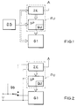
- the arrangement shown in Figure 1 consists of a radio clock FU with a quartz-controlled clock QU, which is synchronized by a time signal receiver ZE via a signal processor SP with the received time signal.
- the time signal receiver ZE has an antenna suitable for receiving the time signal.
- the radio clock FU forms together with one a further device G1 a functional unit, the further device G1 being able to assume operating states which generate such an interference field, which disrupt the reception of the time signal or make it impossible.
- a detector DS is provided which detects such an operating state of the further device G1 and, if such an operating state is present, prevents the synchronization of the quartz-controlled clock QU with the time signal.
- the detector DS is connected to the time signal receiver ZE and suppresses the reception of the time signal when the further device G1 generates strong interference fields.
- the further device G1 can, for. B. a computer, a calculator, a PC, a mainframe, a motor vehicle or a television receiver. What they all have in common is that they generate an interference signal during operation that does not permit the radio-controlled operation of the radio clock at the same time. On the other hand, they do not generate an interference signal when switched off.
- the detector DS monitors the supply of the operating voltage UB to the further device G1. The synchronization takes place only when no operating voltage is supplied to the further device and the latter is thus in the switched-off state.
- the detector consists of a changeover switch which, in alternation with the further device G1, supplies the time signal receiver ZE with the operating voltage. This measure ensures that the time signal receiver ZE can only be put into operation when no operating voltage is supplied to the further device G1 and the latter is switched off.
- the detector consists of a broadband radio receiver which detects the interference radiation generated by the further device G1 and, from a certain intensity of the interference radiation, prevents the synchronization of the quartz-controlled clock QU by the time signal receiver ZE.
- Embodiments of the invention can provide that the next synchronization of the quartz-controlled clock QU takes place after a predetermined period of time has elapsed since the last successful synchronization. This can be achieved that the synchronization z. B. takes place every 24 hours. In the case of periodic operation of the further device G1, the quartz-controlled clock QU is then also synchronized regularly with the time signal.
Landscapes
- Physics & Mathematics (AREA)
- General Physics & Mathematics (AREA)
- Electric Clocks (AREA)
- Synchronisation In Digital Transmission Systems (AREA)
Abstract
Description
Die Erfindung betrifft eine Funkuhr nach dem Oberbegriff des Anspruchs 1.The invention relates to a radio clock according to the preamble of claim 1.
Funkuhren werden im allgemeinen über den Sender DCF-77 der Physikalisch-technischen Bundesanstalt mit einem Zeitzeichensignal versorgt. Eine erste Art von Funkuhren empfängt das Zeitzeichensignal ständig und bringt stets die empfangene Zeit zur Anzeige. Eine zweite Art von Funkuhren synchronisiert eine autonom laufende, quarzgesteuerte Uhr periodisch mit dem Zeitzeichensignal. Insbesondere kleine, batteriebetriebene Funkuhren arbeiten aus Energiespargründen nach dem zweiten Prinzip. Das Synchronisieren des internen Uhrenwerks mit dem Zeitzeichensignal findet typischerweise alle 24 Stunden in den frühen Morgenstunden statt und ist unabhängig von weiteren Faktoren wie z. B. der Empfangsqualität des Zeitzeichensignals oder der Stärke von in der Umgebung vorherrschenden Störfeldern.Radio clocks are generally supplied with a time signal via the transmitter DCF-77 of the Physikalisch-Technische Bundesanstalt. A first type of radio clocks constantly receives the time signal and always displays the time received. A second type of radio controlled clock periodically synchronizes an autonomously running, quartz-controlled clock with the time signal. Small, battery-operated radio-controlled clocks in particular work according to the second principle to save energy. The synchronization of the internal clockwork with the time signal typically takes place every 24 hours in the early morning and is independent of other factors such as e.g. B. the reception quality of the time signal or the strength of prevailing interference fields in the environment.
Es ist weiterhin bekannt, daß viele elektronische Geräte aus dem Gebiet der Signalerzeugung oder Signalverarbeitung Störfelder erzeugen, die andere Funktionen im gleichen Gerät oder Funktionen von in der näheren Umgebung aufgestellter Geräte stören oder unmöglich machen können. Diese Art von Störfeldern unterbinden den Betrieb von Funkuhren in Geräten, wie z. B. PCs, Fernsehern, Videorecordern usw. Bei dem Betrieb derartiger Geräte ist der Empfang des Zeitzeichensignals nur mit sehr großem technischen Aufwand möglich.It is also known that many electronic devices in the field of signal generation or signal processing generate interference fields which can interfere with or make impossible other functions in the same device or functions of devices placed in the vicinity. These types of interference fields prevent operation of radio clocks in devices such as B. PCs, televisions, video recorders, etc. In the operation of such devices, the reception of the time signal is only possible with very great technical effort.
Eine erste Aufgabe der Erfindung ist es, ein Verfahren zum Betreiben einer Funkuhr anzugeben, das den Betrieb der Funkuhr in einer störfeldbehafteten Umgebung gestattet. Diese Aufgabe wird gelöst durch ein Verfahren mit den kennzeichnenden Merkmalen des Anspruchs 1.A first object of the invention is to specify a method for operating a radio clock which allows the radio clock to be operated in an environment subject to interference. This object is achieved by a method having the characterizing features of claim 1.
Es ist eine weitere Aufgabe der Erfindung, eine Funkuhr anzugeben, die für den Betrieb in einer störfeldbehafteten Umgebung geeignet ist. Diese Aufgabe wird durch eine Funkuhr mit den kennzeichnenden Merkmalen des Anspruchs 7 gelöst.It is a further object of the invention to provide a radio clock which is suitable for operation in an environment subject to interference. This object is achieved by a radio clock with the characterizing features of claim 7.
Die vorteilhafte Ausgestaltung der Erfindung erfolgt gemäß den Merkmalen der abhängigen Ansprüche.The advantageous embodiment of the invention takes place according to the features of the dependent claims.
Im folgenden sei ein Ausführungsbeispiel der Erfindung anhand der Figuren erläutert. Dabei zeigen die
- Figur 1
- ein Blockschaltbild der erfindungsgemäßen Funkuhr,
- Figur 2
- eine Ausführungsform der Erfindung.
- Figure 1
- 2 shows a block diagram of the radio clock according to the invention,
- Figure 2
- an embodiment of the invention.
Die in der Figur 1 dargestellte Anordnung besteht aus einer Funkuhr FU mit einer quarzgesteuerten Uhr QU, die durch einen Zeitzeichenempfänger ZE über einen Signalprozessor SP mit dem empfangenen Zeitzeichensignal synchronisiert wird. Der Zeitzeichenempfänger ZE weist eine zum Empfang des Zeitzeichensignals geeignete Antenne auf. Die Funkuhr FU bildet zusammen mit einer weiteren Einrichtung G1 eine Funktionseinheit, wobei die weitere Einrichtung G1 Betriebszustände einnehmen kann, die ein derartiges Störfeld erzeugen, die den Empfang des Zeitzeichensignals stören bzw. unmöglich machen. Erfindungsgemäß ist ein Detektor DS vorgesehen, der einen solchen Betriebszustand der weiteren Einrichtung G1 erkennt und bei Vorliegen eines solchen Betriebszustands die Synchronisierung der quarzgesteuerten Uhr QU mit dem Zeitzeichensignal unterbindet.The arrangement shown in Figure 1 consists of a radio clock FU with a quartz-controlled clock QU, which is synchronized by a time signal receiver ZE via a signal processor SP with the received time signal. The time signal receiver ZE has an antenna suitable for receiving the time signal. The radio clock FU forms together with one a further device G1 a functional unit, the further device G1 being able to assume operating states which generate such an interference field, which disrupt the reception of the time signal or make it impossible. According to the invention, a detector DS is provided which detects such an operating state of the further device G1 and, if such an operating state is present, prevents the synchronization of the quartz-controlled clock QU with the time signal.
In einer vorteilhaften Ausgestaltung der Erfindung ist der Detektor DS mit dem Zeitzeichenempfänger ZE verbunden und unterdrückt den Empfang des Zeitzeichens, wenn die weitere Einrichtung G1 starke Störfelder erzeugt. Die weitere Einrichtung G1 kann z. B. ein Computer, ein Taschenrechner, ein PC, ein Großrechner, ein Kraftfahrzeug oder ein Fernsehempfänger sein. Allen gemeinsam ist, daß sie beim Betrieb ein Störsignal erzeugen, das den gleichzeitigen funkgesteuerten Betrieb der Funkuhr nicht zuläßt. Andererseits erzeugen sie im abgeschalteten Zustand kein Störsignal.In an advantageous embodiment of the invention, the detector DS is connected to the time signal receiver ZE and suppresses the reception of the time signal when the further device G1 generates strong interference fields. The further device G1 can, for. B. a computer, a calculator, a PC, a mainframe, a motor vehicle or a television receiver. What they all have in common is that they generate an interference signal during operation that does not permit the radio-controlled operation of the radio clock at the same time. On the other hand, they do not generate an interference signal when switched off.
In einer weiteren Ausgestaltung der Erfindung überwacht der Detektor DS die Zuführung der Betriebsspannung UB an die weitere Einrichtung G1. Die Synchronisation findet ausschließlich dann statt, wenn der weiteren Einrichtung keine Betriebsspannung zugeführt wird und diese sich somit im ausgeschalteten Zustand befindet. Der Detektor besteht in diesem Fall aus einem Umschalter, der dem Zeitzeichenempfänger ZE im Wechsel zur weiteren Einrichtung G1 die Betriebsspannung zuführt. Durch diese Maßnahme ist gewährleistet, daß der Zeitzeichenempfänger ZE nur dann in Betrieb genommen werden kann, wenn der weiteren Einrichtung G1 keine Betriebsspannung zugeführt wird und diese abgeschaltet ist.In a further embodiment of the invention, the detector DS monitors the supply of the operating voltage UB to the further device G1. The synchronization takes place only when no operating voltage is supplied to the further device and the latter is thus in the switched-off state. In this case, the detector consists of a changeover switch which, in alternation with the further device G1, supplies the time signal receiver ZE with the operating voltage. This measure ensures that the time signal receiver ZE can only be put into operation when no operating voltage is supplied to the further device G1 and the latter is switched off.
In einer weiteren vorteilhaften Ausgestaltung der Erfindung besteht der Detektor aus einem breitbandigen Funkempfänger, der die von der weiteren Einrichtung G1 erzeugte Störstrahlung erfaßt und ab einer gewissen Stärke der Störstrahlung die Synchronisation der quarzgesteuerten Uhr QU durch den Zeitzeichenempfänger ZE unterbindet.In a further advantageous embodiment of the invention, the detector consists of a broadband radio receiver which detects the interference radiation generated by the further device G1 and, from a certain intensity of the interference radiation, prevents the synchronization of the quartz-controlled clock QU by the time signal receiver ZE.
In beiden o. a. Ausführungen der Erfindung kann vorgesehen sein, daß die nächste Synchronisation der quarzgesteuerten Uhr QU nach Ablauf einer festgelegten Zeitspanne seit der letzten erfolgreichen Synchronisation erfolgt. Damit kann erreicht werden, daß die Synchronisierung z. B. alle 24 Stunden erfolgt. Bei einem periodischen Betrieb der weiteren Einrichtung G1 erfolgt dann auch die Synchronisierung der quarzgesteuerten Uhr QU mit dem Zeitzeichensignal regelmäßig.In both of the above Embodiments of the invention can provide that the next synchronization of the quartz-controlled clock QU takes place after a predetermined period of time has elapsed since the last successful synchronization. This can be achieved that the synchronization z. B. takes place every 24 hours. In the case of periodic operation of the further device G1, the quartz-controlled clock QU is then also synchronized regularly with the time signal.
Claims (10)
Applications Claiming Priority (2)
| Application Number | Priority Date | Filing Date | Title |
|---|---|---|---|
| DE4233126 | 1992-10-02 | ||
| DE4233126A DE4233126A1 (en) | 1992-10-02 | 1992-10-02 | Procedure for the operation of a radio clock and radio clock for use in an environment subject to interference |
Publications (3)
| Publication Number | Publication Date |
|---|---|
| EP0590337A1 true EP0590337A1 (en) | 1994-04-06 |
| EP0590337B1 EP0590337B1 (en) | 1996-11-20 |
| EP0590337B2 EP0590337B2 (en) | 2001-01-10 |
Family
ID=6469457
Family Applications (1)
| Application Number | Title | Priority Date | Filing Date |
|---|---|---|---|
| EP93114018A Expired - Lifetime EP0590337B2 (en) | 1992-10-02 | 1993-09-02 | Method for the functioning pf a radio clock and radio clock to be used in an envirenment with disturbed field |
Country Status (5)
| Country | Link |
|---|---|
| US (1) | US5349570A (en) |
| EP (1) | EP0590337B2 (en) |
| KR (1) | KR100248170B1 (en) |
| DE (2) | DE4233126A1 (en) |
| ES (1) | ES2094983T5 (en) |
Cited By (2)
| Publication number | Priority date | Publication date | Assignee | Title |
|---|---|---|---|---|
| EP0892325A1 (en) * | 1997-07-17 | 1999-01-20 | Valeo Electronics GmbH & Co. KG | Radio clock for motor vehicle |
| EP1669818A1 (en) * | 2003-09-30 | 2006-06-14 | Seiko Epson Corporation | Radio controlled clock, electronic device, method for controlling radio controlled clock, and program for controlling reception of radio controlled clock |
Families Citing this family (16)
| Publication number | Priority date | Publication date | Assignee | Title |
|---|---|---|---|---|
| DE4416869A1 (en) * | 1994-05-13 | 1995-11-16 | Opel Adam Ag | Control device for a clock to be synchronized by radio signals |
| US6269055B1 (en) | 1998-11-16 | 2001-07-31 | Quartex, A Division Of Primex, Inc. | Radio-controlled clock movement |
| JP2002541493A (en) | 1999-04-12 | 2002-12-03 | クウォーテックス | Clockwork, clocks and methods for operating them |
| JP3395786B1 (en) * | 2002-02-26 | 2003-04-14 | セイコーエプソン株式会社 | Electronic device, electronic device reception control method, and electronic device reception control program |
| US7012856B2 (en) * | 2002-05-24 | 2006-03-14 | Keith Kibiloski | Radio-controlled clock |
| DE10334990B4 (en) | 2003-07-31 | 2016-03-17 | Atmel Corp. | Radio Clock |
| CN1627213A (en) * | 2003-11-28 | 2005-06-15 | Atmel德国有限公司 | Radio-controlled clock and method for acquiring time information from a time signal |
| US7333467B2 (en) | 2003-12-08 | 2008-02-19 | Atmel Germany Gmbh | Receiver circuit and method using selectively variable amplification for receiving time signals from different transmitters |
| DE10357201A1 (en) * | 2003-12-08 | 2005-07-07 | Atmel Germany Gmbh | Radio Clock |
| DE10361593A1 (en) * | 2003-12-30 | 2005-07-28 | Atmel Germany Gmbh | Method for determining the start of seconds from a transmitted time signal |
| DE102004004416A1 (en) * | 2004-01-29 | 2005-08-18 | Atmel Germany Gmbh | Method for determining the signal quality of a transmitted time signal |
| DE102004004375B4 (en) | 2004-01-29 | 2019-08-08 | Atmel Corp. | Method for obtaining time information and radio clock |
| DE102004004411B4 (en) * | 2004-01-29 | 2015-08-20 | Atmel Corp. | Radio clock and method for obtaining time information |
| DE102004005340A1 (en) * | 2004-02-04 | 2005-09-01 | Atmel Germany Gmbh | Method for obtaining time information, receiver circuit and radio clock |
| DE102005056483B3 (en) | 2005-11-26 | 2007-01-11 | Atmel Germany Gmbh | Time information receiving e.g. for radio clock, involves having characteristic value of temporal duration compared to signal phase of certain signal level of digital signal with desired value |
| JP4873040B2 (en) * | 2009-04-06 | 2012-02-08 | カシオ計算機株式会社 | Analog electronic watch |
Citations (3)
| Publication number | Priority date | Publication date | Assignee | Title |
|---|---|---|---|---|
| JPS54133166A (en) * | 1978-04-06 | 1979-10-16 | Seiko Instr & Electronics Ltd | Electronic watch |
| EP0258838A2 (en) * | 1986-09-01 | 1988-03-09 | Siemens Aktiengesellschaft | Process for actualizing the local time of a user of an information tranfer system |
| JPH03141728A (en) * | 1989-10-27 | 1991-06-17 | Nissan Motor Co Ltd | On-vehicle automatic canceler for gps receiver and telephone set |
Family Cites Families (12)
| Publication number | Priority date | Publication date | Assignee | Title |
|---|---|---|---|---|
| DE258838C (en) * | ||||
| FR1562211A (en) * | 1968-02-19 | 1969-04-04 | Hatot Leon Ets | |
| DE2715096C2 (en) * | 1977-04-04 | 1982-12-16 | Wolfgang Dr.-Ing. 6101 Groß-Bieberau Hilberg | Arrangement for obtaining and displaying time information, consisting of a radio clock and a quartz clock that is spatially combined with this |
| DE2725016A1 (en) * | 1977-05-31 | 1979-02-15 | Hilberg Wolfgang | Combined quartz and radio-controlled clocks - have radio control circuit activated for short duration to correct time-keeping of quartz clock |
| DE2802040A1 (en) * | 1978-01-16 | 1979-07-19 | Peter Gravenhorst | Digital clock system using transmitted time signals - includes internal correction for transmission errors using microcomputer between buffer register store and display |
| JPS56150382A (en) * | 1980-04-24 | 1981-11-20 | Sanyo Electric Co Ltd | Electronic watch |
| DE3128895A1 (en) † | 1981-07-22 | 1983-02-17 | Rainer Dipl.-Ing. 6500 Mainz Bermbach | Noise pulse suppression in radio clocks |
| DE3439638C1 (en) † | 1984-10-30 | 1986-05-15 | Gebrüder Junghans GmbH, 7230 Schramberg | Autonomous radio clock |
| US4823328A (en) * | 1987-08-27 | 1989-04-18 | Conklin Charles C | Radio signal controlled digital clock |
| DE8717549U1 (en) * | 1987-09-23 | 1989-02-02 | Junghans Uhren GmbH, 7230 Schramberg | Autonomous radio clock |
| DE3733965A1 (en) * | 1987-10-08 | 1989-04-20 | Ulrich Dipl Ing Bellmann | Method for obtaining information from strongly mutilated data of a time signal transmitter |
| DE9010813U1 (en) * | 1990-07-20 | 1991-11-14 | Junghans Uhren GmbH, 7230 Schramberg | Autonomous radio clock |
-
1992
- 1992-10-02 DE DE4233126A patent/DE4233126A1/en not_active Withdrawn
-
1993
- 1993-08-05 US US08/102,244 patent/US5349570A/en not_active Expired - Lifetime
- 1993-09-02 DE DE59304528T patent/DE59304528D1/en not_active Expired - Fee Related
- 1993-09-02 ES ES93114018T patent/ES2094983T5/en not_active Expired - Lifetime
- 1993-09-02 EP EP93114018A patent/EP0590337B2/en not_active Expired - Lifetime
- 1993-09-28 KR KR1019930020010A patent/KR100248170B1/en not_active IP Right Cessation
Patent Citations (3)
| Publication number | Priority date | Publication date | Assignee | Title |
|---|---|---|---|---|
| JPS54133166A (en) * | 1978-04-06 | 1979-10-16 | Seiko Instr & Electronics Ltd | Electronic watch |
| EP0258838A2 (en) * | 1986-09-01 | 1988-03-09 | Siemens Aktiengesellschaft | Process for actualizing the local time of a user of an information tranfer system |
| JPH03141728A (en) * | 1989-10-27 | 1991-06-17 | Nissan Motor Co Ltd | On-vehicle automatic canceler for gps receiver and telephone set |
Non-Patent Citations (2)
| Title |
|---|
| PATENT ABSTRACTS OF JAPAN vol. 003, no. 153 (E - 159) 15 December 1979 (1979-12-15) * |
| PATENT ABSTRACTS OF JAPAN vol. 015, no. 359 (E - 1110) 11 September 1991 (1991-09-11) * |
Cited By (4)
| Publication number | Priority date | Publication date | Assignee | Title |
|---|---|---|---|---|
| EP0892325A1 (en) * | 1997-07-17 | 1999-01-20 | Valeo Electronics GmbH & Co. KG | Radio clock for motor vehicle |
| DE19730553A1 (en) * | 1997-07-17 | 1999-01-21 | Valeo Borg Instr Verw Gmbh | Radio clock for motor vehicles |
| EP1669818A1 (en) * | 2003-09-30 | 2006-06-14 | Seiko Epson Corporation | Radio controlled clock, electronic device, method for controlling radio controlled clock, and program for controlling reception of radio controlled clock |
| EP1669818A4 (en) * | 2003-09-30 | 2008-03-05 | Seiko Epson Corp | Radio controlled clock, electronic device, method for controlling radio controlled clock, and program for controlling reception of radio controlled clock |
Also Published As
| Publication number | Publication date |
|---|---|
| KR100248170B1 (en) | 2000-03-15 |
| ES2094983T3 (en) | 1997-02-01 |
| EP0590337B2 (en) | 2001-01-10 |
| EP0590337B1 (en) | 1996-11-20 |
| KR940009789A (en) | 1994-05-24 |
| DE59304528D1 (en) | 1997-01-02 |
| ES2094983T5 (en) | 2001-03-16 |
| DE4233126A1 (en) | 1994-04-07 |
| US5349570A (en) | 1994-09-20 |
Similar Documents
| Publication | Publication Date | Title |
|---|---|---|
| EP0590337B1 (en) | Method for the functioning pf a radio clock and radio clock to be used in an envirenment with disturbed field | |
| DE2749512C2 (en) | Switching device for electronic clocks | |
| DE3786529T2 (en) | Control of high frequency response pulses in a television survey system. | |
| DE68928359T2 (en) | Automatic antenna tuning | |
| DE69325689T2 (en) | ELECTRONIC CLOCK WITH POINT INDICATOR | |
| EP0355567A2 (en) | Date and time correcting device and method therefor | |
| DE10349476A1 (en) | Timely execution of a measurement or control action and synchronization of several such actions | |
| EP0650259A1 (en) | Clock signal generator circuit | |
| DE2643250B2 (en) | Centrally controlled clock | |
| EP0806713B1 (en) | Control device with a tunable standby-oscillator | |
| EP0015873A1 (en) | Oscillator with a low frequency quartz resonator | |
| DE19528702A1 (en) | Clock recovery device, receiver and transmission device containing them as a component, and radio frequency signal used by them | |
| DE10334990B4 (en) | Radio Clock | |
| DE3443859C2 (en) | ||
| WO2011015266A2 (en) | Electronic circuit for timer applications having minimal power consumption and methods for calibrating and operating the same | |
| DE4423366C1 (en) | Software clock operating method for electronic entertainment appts. e.g with TV receiver or video recorder | |
| DE3540380A1 (en) | Superheterodyne receiver circuit for an electrical radio clock | |
| DE2539224B2 (en) | Procedure for automatically correcting the time display of a watch and clock to perform this procedure | |
| DE2716387B2 (en) | Electronic clock | |
| EP1927053A1 (en) | Microcontroller and method for the operation thereof | |
| DE19626869C2 (en) | Circuit arrangement with at least one digital circuit and a monitoring circuit | |
| DE10225748B4 (en) | Method of programming key-programmable clocks and programming keys for implementing this method | |
| DE3428698C2 (en) | ||
| DE4311942C2 (en) | Device with a receiver circuit for receiving television text signals | |
| DE3038727C2 (en) | Electronic clockwork |
Legal Events
| Date | Code | Title | Description |
|---|---|---|---|
| PUAI | Public reference made under article 153(3) epc to a published international application that has entered the european phase |
Free format text: ORIGINAL CODE: 0009012 |
|
| AK | Designated contracting states |
Kind code of ref document: A1 Designated state(s): DE ES FR GB IT SE |
|
| 17P | Request for examination filed |
Effective date: 19940325 |
|
| 17Q | First examination report despatched |
Effective date: 19950911 |
|
| GRAG | Despatch of communication of intention to grant |
Free format text: ORIGINAL CODE: EPIDOS AGRA |
|
| GRAH | Despatch of communication of intention to grant a patent |
Free format text: ORIGINAL CODE: EPIDOS IGRA |
|
| GRAH | Despatch of communication of intention to grant a patent |
Free format text: ORIGINAL CODE: EPIDOS IGRA |
|
| GRAA | (expected) grant |
Free format text: ORIGINAL CODE: 0009210 |
|
| ITF | It: translation for a ep patent filed | ||
| AK | Designated contracting states |
Kind code of ref document: B1 Designated state(s): DE ES FR GB IT SE |
|
| GBT | Gb: translation of ep patent filed (gb section 77(6)(a)/1977) |
Effective date: 19961122 |
|
| REF | Corresponds to: |
Ref document number: 59304528 Country of ref document: DE Date of ref document: 19970102 |
|
| REG | Reference to a national code |
Ref country code: ES Ref legal event code: FG2A Ref document number: 2094983 Country of ref document: ES Kind code of ref document: T3 |
|
| ET | Fr: translation filed | ||
| PLAV | Examination of admissibility of opposition |
Free format text: ORIGINAL CODE: EPIDOS OPEX |
|
| PLBQ | Unpublished change to opponent data |
Free format text: ORIGINAL CODE: EPIDOS OPPO |
|
| PLBI | Opposition filed |
Free format text: ORIGINAL CODE: 0009260 |
|
| 26 | Opposition filed |
Opponent name: JUNGHANS UHREN GMBH Effective date: 19970813 |
|
| PLBF | Reply of patent proprietor to notice(s) of opposition |
Free format text: ORIGINAL CODE: EPIDOS OBSO |
|
| PLBF | Reply of patent proprietor to notice(s) of opposition |
Free format text: ORIGINAL CODE: EPIDOS OBSO |
|
| REG | Reference to a national code |
Ref country code: GB Ref legal event code: 732E |
|
| REG | Reference to a national code |
Ref country code: FR Ref legal event code: TP |
|
| PLAW | Interlocutory decision in opposition |
Free format text: ORIGINAL CODE: EPIDOS IDOP |
|
| RAP2 | Party data changed (patent owner data changed or rights of a patent transferred) |
Owner name: TEMIC TELEFUNKEN MICROELECTRONIC GMBH |
|
| PLAW | Interlocutory decision in opposition |
Free format text: ORIGINAL CODE: EPIDOS IDOP |
|
| PGFP | Annual fee paid to national office [announced via postgrant information from national office to epo] |
Ref country code: ES Payment date: 20000922 Year of fee payment: 8 |
|
| PUAH | Patent maintained in amended form |
Free format text: ORIGINAL CODE: 0009272 |
|
| STAA | Information on the status of an ep patent application or granted ep patent |
Free format text: STATUS: PATENT MAINTAINED AS AMENDED |
|
| 27A | Patent maintained in amended form |
Effective date: 20010110 |
|
| AK | Designated contracting states |
Kind code of ref document: B2 Designated state(s): DE ES FR GB IT SE |
|
| GBTA | Gb: translation of amended ep patent filed (gb section 77(6)(b)/1977) | ||
| REG | Reference to a national code |
Ref country code: ES Ref legal event code: DC2A Kind code of ref document: T5 Effective date: 20010214 |
|
| ET3 | Fr: translation filed ** decision concerning opposition | ||
| ITF | It: translation for a ep patent filed | ||
| PGFP | Annual fee paid to national office [announced via postgrant information from national office to epo] |
Ref country code: GB Payment date: 20010814 Year of fee payment: 9 |
|
| PGFP | Annual fee paid to national office [announced via postgrant information from national office to epo] |
Ref country code: SE Payment date: 20010827 Year of fee payment: 9 |
|
| PGFP | Annual fee paid to national office [announced via postgrant information from national office to epo] |
Ref country code: FR Payment date: 20010904 Year of fee payment: 9 |
|
| REG | Reference to a national code |
Ref country code: GB Ref legal event code: IF02 |
|
| PG25 | Lapsed in a contracting state [announced via postgrant information from national office to epo] |
Ref country code: GB Free format text: LAPSE BECAUSE OF NON-PAYMENT OF DUE FEES Effective date: 20020902 |
|
| PG25 | Lapsed in a contracting state [announced via postgrant information from national office to epo] |
Ref country code: SE Free format text: LAPSE BECAUSE OF NON-PAYMENT OF DUE FEES Effective date: 20020903 Ref country code: ES Free format text: LAPSE BECAUSE OF NON-PAYMENT OF DUE FEES Effective date: 20020903 |
|
| GBPC | Gb: european patent ceased through non-payment of renewal fee |
Effective date: 20020902 |
|
| EUG | Se: european patent has lapsed | ||
| PG25 | Lapsed in a contracting state [announced via postgrant information from national office to epo] |
Ref country code: FR Free format text: LAPSE BECAUSE OF NON-PAYMENT OF DUE FEES Effective date: 20030603 |
|
| REG | Reference to a national code |
Ref country code: FR Ref legal event code: ST |
|
| REG | Reference to a national code |
Ref country code: ES Ref legal event code: FD2A Effective date: 20031011 |
|
| PG25 | Lapsed in a contracting state [announced via postgrant information from national office to epo] |
Ref country code: IT Free format text: LAPSE BECAUSE OF NON-PAYMENT OF DUE FEES Effective date: 20050902 |
|
| PGFP | Annual fee paid to national office [announced via postgrant information from national office to epo] |
Ref country code: DE Payment date: 20080919 Year of fee payment: 16 |
|
| PG25 | Lapsed in a contracting state [announced via postgrant information from national office to epo] |
Ref country code: DE Free format text: LAPSE BECAUSE OF NON-PAYMENT OF DUE FEES Effective date: 20100401 |