EP0806713B1 - Control device with a tunable standby-oscillator - Google Patents
Control device with a tunable standby-oscillator Download PDFInfo
- Publication number
- EP0806713B1 EP0806713B1 EP97107367A EP97107367A EP0806713B1 EP 0806713 B1 EP0806713 B1 EP 0806713B1 EP 97107367 A EP97107367 A EP 97107367A EP 97107367 A EP97107367 A EP 97107367A EP 0806713 B1 EP0806713 B1 EP 0806713B1
- Authority
- EP
- European Patent Office
- Prior art keywords
- frequency
- oscillator
- standby
- control circuit
- during
- Prior art date
- Legal status (The legal status is an assumption and is not a legal conclusion. Google has not performed a legal analysis and makes no representation as to the accuracy of the status listed.)
- Expired - Lifetime
Links
Images
Classifications
-
- E—FIXED CONSTRUCTIONS
- E05—LOCKS; KEYS; WINDOW OR DOOR FITTINGS; SAFES
- E05B—LOCKS; ACCESSORIES THEREFOR; HANDCUFFS
- E05B77/00—Vehicle locks characterised by special functions or purposes
- E05B77/46—Locking several wings simultaneously
- E05B77/48—Locking several wings simultaneously by electrical means
-
- G—PHYSICS
- G04—HOROLOGY
- G04G—ELECTRONIC TIME-PIECES
- G04G3/00—Producing timing pulses
- G04G3/02—Circuits for deriving low frequency timing pulses from pulses of higher frequency
Definitions
- the invention relates to a control circuit by means of which electrical Devices can be controlled and their operating states can be monitored.
- control circuit for example, a central locking device controlled and monitored a motor vehicle.
- a control circuit for controlling and Monitoring of a so-called state machine can be used, the can produce a predetermined number of states due to current states and input variables from one state to another changes state and generates output signals.
- From DE 42 21 142 A1 is a central locking system for a Motor vehicle known that housed a in a door key Transmitter and a receiver housed in the motor vehicle.
- a code is sent by the transmitter, which decodes by the receiver is and leads to the actuation of the central locking system, if the correct code has been sent.
- Form transmitter and receiver thus a remote control device. So that this either can work with radio frequencies or with light frequencies both an RF oscillator and a light wave oscillator, the RF carrier or light wave each with the transmission-side code word can be modulated, and both an RF detector and receiver also a light wave detector is provided, the output signals of which common decoder are performed.
- US 4,857,917 A is a remote-controlled central locking system known for a motor vehicle, the arranged in the motor vehicle Receiver is switched on and off periodically to the Reduce overall power consumption. So when sending out a Code signal from one transmitter to the central locking system on each If responding, the code pulse sequence on the transmission side becomes a guide pulse sent forward, the duration of which is longer than the temporal Distance between two successive switch-on intervals of the receiver. In this way the receiver is safely activated by the guide impulse, to then receive and process the code pulse sequence can.
- the receiver is equipped with a clock pulse generator equipped, which corresponds to the switch-on intervals of the receiver Clock pulses to a first input of an AND logic circuit supplies.
- a second input of the AND logic circuit are received and shaped impulses from the transmitter fed. If the timer generates a pulse during a clock pulse received by the transmitter, triggers the resulting output signal the AND logic circuit a monostable multivibrator, whose output signal for a predetermined period of time, which at least is as long as that from the transmitter following a lead pulse sent code pulse train, a power supply to the receiver turns. Is no pulse during a clock pulse from the timer received by the transmitter, the power supply to the receiver only switched on for the respective duration of the clock pulse.
- a RAM circuit which is for a Refresh operation in an active operating state and otherwise in a standby operating state is switchable.
- An oscillator is provided whose frequency is switchable, depending on whether the RAM circuit in the refresh mode or in the standby mode located.
- EP 0 457 964 A1 describes a telecontrol system for controlling Vehicle additional devices are known, the ones arranged in the vehicle Receiver is switched on and off periodically to the average To reduce the power consumption of the receiver.
- sending the transmitter is switched on for a period of time, so is great that in their time at least one switch-on interval of the receiver falls, so the receiver is definitely on a send can react.
- EP-A-0 586 256 discloses a time measurement system with two oscillators different frequency known. By means of an error calibration device the frequencies of the two oscillators are compared. through A selector will either count the frequency of the faster on a counter Given the oscillator or the frequency of the slower oscillator.
- an oscillator circuit is known, the one has a high-frequency oscillator and a low-frequency oscillator. At least the low-frequency oscillator is one Crystal oscillator. The frequency of the high-frequency oscillator is up divided the frequency of the low frequency oscillator. The frequency of the low frequency oscillator and the divided frequency of the high frequency oscillator are both on a differential frequency generator given at the output of a correction signal if the divided frequency of the high frequency oscillator and the frequency of the low-frequency oscillator differ from each other.
- the Correction signal affects a programmable frequency divider that divides the output signal of the low-frequency oscillator.
- the high frequency crystal oscillator turns every 15 minutes for about 16 seconds switched on. During this respective duty cycle the Programmable frequency dividers reset each time.
- the two Oscillators themselves each have a fixed frequency.
- DE 43 02 232 A1 describes a device for operating a Microprocessor known, by means of which the microprocessor in one can be operated actively and in an inactive operating state, to conserve the battery that powers the microprocessor.
- the microprocessor In the inactive state, the microprocessor can either be triggered by a wake-up signal a watchdog arranged in the microprocessor or by an external wake-up signal, periodically from an external Oscillator is released, brought into the active state.
- the external oscillator is built with two CMOS inverters.
- a conventional control circuit of the type mentioned includes a control device, which is a microcontroller can act, and a main oscillator, which is a clock signal for the Operation of the control device delivers.
- a control device which is a microcontroller can act
- a main oscillator which is a clock signal for the Operation of the control device delivers.
- Such Control circuit contain a condition monitoring device, by means of which the respective states of predetermined electrical devices, such as electrical switch contacts, sensors and / or detectors can be monitored and represent the respective states to the control device Status signals are available.
- the control circuit becomes a functional safety even when none There is a need for tax, repeated for a short wake-up period switched back to full operation. Such a temporary downshift in full operation usually happens periodically. For example takes place after standby periods with a duration of each a few seconds switch back to full operation for a wake-up time of a few milliseconds each. In this example there is the control circuit only in the range of a few ⁇ of the total time in Full operation, the rest of the time in standby mode. The average Power consumption by the control circuit parts with significant Power consumption is reduced accordingly to a few ⁇ of that Power consumption that would occur if the control circuit was permanent would be kept in full operation.
- the control circuit according to the invention is at times without tax requirement switchable to standby mode and during standby mode repeated for a short wake-up time in full operation gurschaltbar. It has a full operating circuit part, the is only operable during full operation of the control circuit and a frequency-stable main oscillator with a relatively high power requirement having. It includes a standby circuit section, which is both in full operation as well as in standby mode and one in itself low-frequency, tunable standby oscillator with low Has electricity requirements. The standby oscillator is used during wake-up times tuned with the help of the main oscillator.
- the full operating circuit part comprises a control device and contains the standby circuit part a frequency control device in which the oscillator frequency of the Standby oscillator controlling frequency control signal can be stored, and a wake-up device controlled by an output signal of the standby oscillator, by means of which during the wake-up times each at least the control device and the main oscillator in full operation are feasible.
- a frequency measuring device is provided by means of which during the wake-up times a measurement of the Actual oscillator frequency of the standby oscillator can be carried out.
- This Embodiment has a frequency correction device, by means of which is the actual oscillator frequency measured during the respective wake-up time is comparable to an oscillator target frequency and by means of which one depends on the respective comparison result corrected frequency control signal can be generated and each as a new frequency control signal can be stored in the frequency control device.
- every wake-up operation is carried out the actual frequency of the standby oscillator measured and at a Deviation of the actual frequency of the standby oscillator from its target frequency tuning the standby oscillator to the desired one Target frequency causes. Because of the relatively short time intervals the standby oscillator stops between the individual wake-up times thus, despite its inherently poor frequency constancy, its target frequency with very high reliability.
- the control circuit contains a condition monitoring device by means of which Standby operation of the control circuit predetermines the respective states Sensors and / or detectors and / or other types of electrical Facilities can be monitored and the control circuit at the Determination of predetermined conditions can be switched back to full operation.
- the control circuit can have a microcontroller that at least has an interrupt input through which the microcontroller standby can be switched back to full operation.
- the frequency of the Standby oscillator controllable by means of a digital frequency control signal his When using an IC oscillator as a standby oscillator can have a plurality of differently weighted tuning current sources be provided, determined with the digital frequency control signal which of the tuning current sources is used to charge one Capacity of the standby oscillator.
- the frequency control device can have a frequency control signal register, in which the frequency control signal that occurs during the respective Wake-up time from a comparison of the actual and target frequency of the Standby oscillator has resulted, is storable and its memory content determines the respective frequency of the standby oscillator.
- the frequency measuring device can have a time window device, by means of which a time window within the respective wake-up period with one of the actual oscillation period duration of the standby oscillator dependent window duration opened, the number of during the Window duration occurring oscillations of the main oscillator are counted and the count value thus obtained by means of a frequency comparison device with one of the oscillation period set duration of the Standby oscillator corresponding reference count is compared.
- the control circuit according to the invention is suitable for a central locking device for a motor vehicle that have multiple electrical Has switch contacts, for example, in different places locking locks of the motor vehicle are assigned and of which upon actuation of the central locking device at least a part changes its switching state.
- the control circuit can switch states at least some of the switch contacts are monitored. Will in Standby mode a change in the switching state of at least one of the electrical contacts are detected, the system switches back to full operation.
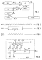
- a control circuit comprises as a control device a microcontroller ⁇ C, which under the timing control as a Quartz oscillator trained main oscillator MOSC, of which the Microcontroller ⁇ C via a first microcontroller input IN1 Main clock signal MCLK received.
- This control circuit also includes a standby oscillator SBOSC, which is a standby clock signal SBCLK generated. This is given to a wake-up circuit WUP. This periodically generates an under control of the standby clock signal SBCLK Wake-up signal sent to an interrupt input INT of the microcontroller ⁇ C delivers.
- the wake-up signal is generated with every nth clock pulse of the standby clock signal SBCLK, where n is any can be an integer.
- the frequency of the standby oscillator SBOSC is tunable by means of a digital frequency control signal FCS, which is in a frequency control signal register FCR can be saved.
- FCS digital frequency control signal
- FCR frequency control signal register
- the control circuit also has a frequency measuring device TIMER on that with the microcontroller via a data bus DB in Connection is established.
- the frequency measuring device TIMER has one Time measurement input ZE on, to the output of an AND logic circuit A is connected to the one with the output of the main oscillator MOSC connected first input E1, one with a Output of a gate logic GL connected to the second input E2 and has an output O connected to the time measurement input ZE.
- the gate logic GL has a logic input LE to which the standby clock signal SBCLK is fed.
- the gate logic GL generates on one Logic output LA timed by SBCLK within one every m-th wake-up time, where m is any integer can and is preferably equal to 1, a window signal GATE which the Duration of a time window TF (Fig. 3) determined and on the one hand the second Input E2 from A and on the other hand a second microcontroller input IN2 is supplied.
- a window signal GATE which the Duration of a time window TF (Fig. 3) determined and on the one hand the second Input E2 from A and on the other hand a second microcontroller input IN2 is supplied.
- this window signal GATE is the AND gate A for the main clock signal MCLK (Fig. 2) of the main oscillator MOSC permeable.
- the frequency measuring device TIMER counts the number of you during each Time window TF supplied clock pulses of the main clock signal MCLK (Fig. 4).
- the microcontroller ⁇ C asks about the Data bus DB from the frequency measuring device TIMER at the end of Time window TF reached count value.
- the main oscillator MOSC has a frequency of 8, for example MHz and the standby oscillator SBOSC has e.g. a frequency of 32 KHz.
- the time window TF which strictly with the frequency of the Standby oscillator SBOSC is correlated and for example the duration of a clock pulse from SBCLK, therefore, fit essentially in practice more clock pulses MCLK than is shown in Figures 2 to 4.
- a setpoint value, which is one, is stored in the microcontroller ⁇ C corresponds to the predetermined target frequency of the standby oscillator SBOSC.
- the one at the end of a TF time window from TIMER to the microcontroller ⁇ C delivered count value, which the respective actual frequency of the Standby oscillator corresponds to SBOSC and is therefore referred to as the actual count value is compared in the microcontroller ⁇ C with the target count value. If the actual count value deviates from the target count value, it is generated the microcontroller ⁇ C a correction signal and depending of which a digital frequency control signal FCS, which from the microcontroller ⁇ C via the data bus DB into the frequency control signal register FCR is registered. In addition, the TIMER is switched back to one Initial count value reset from 0, for example.
- the one written into the frequency control signal register FCR Frequency control signal determines the respective frequency of the standby oscillator SBOSC until the frequency control signal register FCR from Microcontroller ⁇ C a new frequency control signal is delivered.
- FIG. 5 shows a preferred embodiment of one for the invention Control circuit suitable standby oscillator SBOSC.
- This Standby oscillator is constructed as an IC oscillator in a manner known per se, so as an oscillator that has a capacitor that is periodic alternately charged by means of a power source device and is discharged using a switch.
- the oscillator shown in Figure 5 includes one between a supply voltage source UB and a ground connection GND switched Series connection with a capacitor C and four parallel to each other switched current sources S1 to S4.
- the capacitor C is a first one Switch SW1 connected in parallel.
- a node P between that Capacitor C and the current sources S1 to S4 has one input a comparator COM connected, the output signal of the switching state of the switch SW1 controls.
- the current source S1 serves as the main current source and is permanently connected to the capacitor C.
- the Current sources S2 to S4 serve as tuning current sources.
- each of the tuning current sources S2 to S4 and the voltage supply source UB is one of three switches SW2 to SW4 switched.
- the switching states of the switches SW2 to SW4 are determined by means of switch control signals FCS1, FCS2 or FCS3 controlled, which are by different bit positions of the in the frequency control signal register FCR stored frequency control signal FCS.
- the tuning current sources S2 to S4 deliver different sized current values I 1 or I 1/2 or I 1/4 and are weighted according to the dual number system.
- the oscillator shown in Figure 5 functions such that the capacitor C with switch SW1 open with at least the current Main power source S1 is charged.
- the charging voltage of the capacitor C increases accordingly until this charging voltage reaches a predetermined one Reference value reached, whereupon the comparator COM Output signal generated, which the switch SW1 in its conductive Condition leads to a sudden discharge of the capacitor C leads.
- This alternating charging and discharging of the capacitor repeats itself periodically, the steepness of the rise in the charging voltage and thus the respective duration of the charging process from depends on the charging current. This in turn depends on how many the tuning current sources S2 to S4 by means of the associated switches SW2 to SW4 are switched on. And this is through that in the frequency control signal register FCR each stored digital frequency control signal FCS determined.
- the wake-up circuit WUP When using the control circuit for a central locking device of a motor vehicle can the wake-up circuit WUP simultaneously can be used as condition monitoring device, by means of which the respective states of predetermined (not shown) sensors and / or detectors or other electrical devices, for example of electrical switch contacts, the various Locking locks of the motor vehicle are monitored become.
- this standby mode is under control of the standby clock signal SBCLK from the wake-up circuit WUP periodically after the microcontroller at certain intervals, for example every 1 s ⁇ C via the INT input for a respective wake-up time of for example 1 ms turned on, which also turns on the main oscillator MOSC leads.
- the respective wake-up time generated a time window TF by means of the gate logic GL, with the help of ⁇ C the comparison between the actual frequency and the target frequency of the Standby oscillator SBOSC performed and the result of this Comparison dependent new frequency control signal in the frequency control signal register FCR registered, leading to appropriate control the switches SW2 to SW4 of the standby oscillator shown in Figure 5 SBOSC leads.
- the microcontroller ⁇ C and the main oscillator MOSC switched off again.
- the wake-up circuit Restores the wake-up circuit to one or more of the electrical contacts monitored by her during a change of state a standby time period, it gives immediately, d. i.e. without the wait for the next wake-up time, one via the interrupt input INT Interrupt command to the microcontroller acting as a wake-up signal ⁇ C, whereupon this and the main oscillator MOSC are switched on, the control circuit is thus switched back to full operation. Since the microcontroller ⁇ C is switched off by a stop command the microcontroller ⁇ C sets its own every time it is woken up Operation continues in the program step in which it was previously carried out the stop command has been switched off.
Description
Die Erfindung betrifft eine Steuerschaltung, mittels welcher elektrische Einrichtungen steuerbar und deren Betriebszustände überwachbar sind.The invention relates to a control circuit by means of which electrical Devices can be controlled and their operating states can be monitored.
Mit einer derartigen Steuerschaltung wird beispielsweise eine Zentralverriegelungseinrichtung eines Kraftfahrzeugs gesteuert und überwacht. Ganz allgemein ist eine derartige Steuerschaltung zur Steuerung und Überwachung eines sogenannten Zustandsautomaten verwendbar, der eine vorbestimmte Zahl von Zuständen produzieren kann, aufgrund von aktuellen Zuständen und Eingangsvariablen von einem Zustand in einen anderen Zustand übergeht und dabei Ausgangssignale erzeugt.With such a control circuit, for example, a central locking device controlled and monitored a motor vehicle. Such a control circuit for controlling and Monitoring of a so-called state machine can be used, the can produce a predetermined number of states due to current states and input variables from one state to another changes state and generates output signals.
Aus der DE 42 21 142 A1 ist eine Zentralverriegelungsanlage für ein Kraftfahrzeug bekannt, die einen in einem Türschlüssel untergebrachten Sender und einen im Kraftfahrzeug untergebrachten Empfänger umfaßt. Mittels des Senders wird ein Code gesendet, der vom Empfänger decodiert wird und zur Betätigung der Zentralverriegelungsanlage führt, wenn der richtige Code gesendet worden ist. Sender und Empfänger bilden somit eine Fernbetätigungseinrichtung. Damit diese wahlweise entweder mit Funkfrequenzen oder mit Lichtfrequenzen arbeiten kann, sind sendeseitig sowohl ein HF-Oszillator als auch ein Lichtwellenoszillator, deren HF-Träger beziehungsweise Lichtwelle je mit dem sendeseitigen Codewort modulierbar sind, und empfängerseitig sowohl ein HF-Detektor als auch ein Lichtwellendetektor vorgesehen, deren Ausgangssignale auf eine gemeinsame Decodiereinrichtung geführt werden.From DE 42 21 142 A1 is a central locking system for a Motor vehicle known that housed a in a door key Transmitter and a receiver housed in the motor vehicle. A code is sent by the transmitter, which decodes by the receiver is and leads to the actuation of the central locking system, if the correct code has been sent. Form transmitter and receiver thus a remote control device. So that this either can work with radio frequencies or with light frequencies both an RF oscillator and a light wave oscillator, the RF carrier or light wave each with the transmission-side code word can be modulated, and both an RF detector and receiver also a light wave detector is provided, the output signals of which common decoder are performed.
Aus der US 4 857 917 A ist eine fernbedienbare Zentralverriegelungsanlage für ein Kraftfahrzeug bekannt, deren im Kraftfahrzeug angeordneter Empfänger periodisch ein- und ausgeschaltet wird, um den Gesamtstromverbrauch zu reduzieren. Damit bei der Aussendung eines Codesignals von einem Sender die Zentralverriegelungsanlage auf jeden Fall reagiert, wird der sendeseitigen Codeimpulsfolge ein Führungsimpuls vorausgeschickt, dessen Zeitdauer länger ist als der zeitliche Abstand zweier aufeinanderfolgender Einschaltintervalle des Empfängers. Auf diese Weise wird der Empfänger vom Führungsimpuls sicher aktiviert, um daraufhin die Codeimpulsfolge empfangen und verarbeiten zu können. Zu diesem Zweck ist der Empfänger mit einem Taktimpulsgeber ausgestattet, welcher den Einschaltintervallen des Empfängers entsprechende Taktimpulse an einen ersten Eingang einer UND-Verknüpfungsschaltung liefert. Einem zweiten Eingang der UND-Verknüpfungsschaltung werden vom Sender empfangene und geformte Impulse zugeführt. Wird während eines Taktimpulses vom Timer ein Impuls vom Sender empfangen, triggert das dann entstehende Ausgangssignal der UND-Verknüpfungsschaltung eine monostabile Kippschaltung, deren Ausgangssignal für eine vorbestimmte Zeitdauer, welche mindestens so lang ist wie die vom Sender im Anschluß an einen Führungsimpuls gesendete Codeimpulsfolge, eine Stromversorgung des Empfängers einschaltet. Ist während eines Taktimpulses vom Timer kein Impuls vom Sender empfangen worden, wird die Stromversorgung des Empfängers nur für die jeweilige Zeitdauer des Taktimpulses eingeschaltet.From US 4,857,917 A is a remote-controlled central locking system known for a motor vehicle, the arranged in the motor vehicle Receiver is switched on and off periodically to the Reduce overall power consumption. So when sending out a Code signal from one transmitter to the central locking system on each If responding, the code pulse sequence on the transmission side becomes a guide pulse sent forward, the duration of which is longer than the temporal Distance between two successive switch-on intervals of the receiver. In this way the receiver is safely activated by the guide impulse, to then receive and process the code pulse sequence can. For this purpose the receiver is equipped with a clock pulse generator equipped, which corresponds to the switch-on intervals of the receiver Clock pulses to a first input of an AND logic circuit supplies. A second input of the AND logic circuit are received and shaped impulses from the transmitter fed. If the timer generates a pulse during a clock pulse received by the transmitter, triggers the resulting output signal the AND logic circuit a monostable multivibrator, whose output signal for a predetermined period of time, which at least is as long as that from the transmitter following a lead pulse sent code pulse train, a power supply to the receiver turns. Is no pulse during a clock pulse from the timer received by the transmitter, the power supply to the receiver only switched on for the respective duration of the clock pulse.
Aus der EP-B-0 118 108 ist eine RAM-Schaltung bekannt, die für einen Auffrischungsbetrieb in einen aktiven Betriebszustand und ansonsten in einen Standby-Betriebszustand schaltbar ist. Es ist ein Oszillator vorgesehen, dessen Frequenz umschaltbar ist, und zwar je nach dem ob sich die RAM-Schaltung im Auffrischungsbetrieb oder im Standby-Betrieb befindet. From EP-B-0 118 108 a RAM circuit is known which is for a Refresh operation in an active operating state and otherwise in a standby operating state is switchable. An oscillator is provided whose frequency is switchable, depending on whether the RAM circuit in the refresh mode or in the standby mode located.
Aus der EP 0 457 964 A1 ist eine Fernwirkanlage zur Ansteuerung von Fahrzeugzusatzeinrichtungen bekannt, deren im Fahrzeug angeordneter Empfänger periodisch ein- und ausgeschaltet wird, um den durchschnittlichen Strombedarf des Empfängers herabzusetzen. Bei einem Sendevorgang wird der Sender jeweils für eine Zeitdauer eingeschaltet, die so groß ist, daß in ihre Zeit mindestens ein Einschaltintervall des Empfängers fällt, so daß der Empfänger auf jeden Fall auf einen Sendevorgang reagieren kann.EP 0 457 964 A1 describes a telecontrol system for controlling Vehicle additional devices are known, the ones arranged in the vehicle Receiver is switched on and off periodically to the average To reduce the power consumption of the receiver. When sending the transmitter is switched on for a period of time, so is great that in their time at least one switch-on interval of the receiver falls, so the receiver is definitely on a send can react.
Aus der EP-A-0 586 256 ist ein Zeitmeßsystem mit zwei Oszillatoren unterschiedlicher Frequenz bekannt. Mittels einer Fehlerkalibriereinrichtung werden die Frequenzen der beiden Oszillatoren verglichen. Mittels eines Selektors wird auf einen Zähler entweder die Frequenz des schnelleren Oszillators oder die Frequenz des langsameren Oszillators gegeben.EP-A-0 586 256 discloses a time measurement system with two oscillators different frequency known. By means of an error calibration device the frequencies of the two oscillators are compared. through A selector will either count the frequency of the faster on a counter Given the oscillator or the frequency of the slower oscillator.
Aus der EP-B-0 015 873 ist eine Oszillatorschaltung bekannt, die einen hochfrequenten Oszillator und einen niederfrequenten Oszillator aufweist. Mindestens bei dem niederfrequenten Oszillator handelt es sich um einen Quarzoszillator. Die Frequenz des hochfrequenten Oszillators wird auf die Frequenz des niederfrequenten Oszillators herabgeteilt. Die Frequenz des niederfrequenten Oszillators und die herabgeteilte Frequenz des hochfrequenten Oszillators werden beide auf einen Differenzfrequenzgenerator gegeben, an dessen Ausgang ein Korrektursignal entsteht, wenn die herabgeteilte Frequenz des hochfrequenten Oszillators und die Frequenz des niederfrequenten Oszillators voneinander abweichen. Das Korrektursignal beeinflußt einen programmierbaren Frequenzteiler, der das Ausgangssignal des niederfrequenten Oszillators herabteilt. Der hochfrequente Quarzoszillator wird alle 15 Minuten für etwa 16 Sekunden eingeschaltet. Während dieser jeweiligen Einschaltdauer wird der programmierbare Frequenzteiler jeweils neu eingestellt. Die beiden Oszillatoren selbst haben je eine feste Frequenz.From EP-B-0 015 873 an oscillator circuit is known, the one has a high-frequency oscillator and a low-frequency oscillator. At least the low-frequency oscillator is one Crystal oscillator. The frequency of the high-frequency oscillator is up divided the frequency of the low frequency oscillator. The frequency of the low frequency oscillator and the divided frequency of the high frequency oscillator are both on a differential frequency generator given at the output of a correction signal if the divided frequency of the high frequency oscillator and the frequency of the low-frequency oscillator differ from each other. The Correction signal affects a programmable frequency divider that divides the output signal of the low-frequency oscillator. The high frequency crystal oscillator turns every 15 minutes for about 16 seconds switched on. During this respective duty cycle the Programmable frequency dividers reset each time. The two Oscillators themselves each have a fixed frequency.
Aus der DE 43 02 232 A1 ist eine Vorrichtung zum Betreiben eines Mikroprozessors bekannt, mittels welcher der Mikroprozessor in einem aktiven und in einem inaktiven Betriebszustand betrieben werden kann, um die den Mikroprozessor mit Strom versorgende Batterie zu schonen. Im inaktiven Zustand kann der Mikroprozessor entweder durch ein Aufwecksignal eines im Mikroprozessor angeordneten Watchdog oder durch ein externes Aufwecksignal, das periodisch von einem externen Oszillator abgegeben wird, in den aktiven Zustand gebracht werden. Der externe Oszillator ist mit zwei CMOS-Invertern aufgebaut.DE 43 02 232 A1 describes a device for operating a Microprocessor known, by means of which the microprocessor in one can be operated actively and in an inactive operating state, to conserve the battery that powers the microprocessor. In the inactive state, the microprocessor can either be triggered by a wake-up signal a watchdog arranged in the microprocessor or by an external wake-up signal, periodically from an external Oscillator is released, brought into the active state. The external oscillator is built with two CMOS inverters.
Eine herkömmliche Steuerschaltung der eingangs angegebenen Art umfaßt eine Steuereinrichtung, bei der es sich um einen Mikrocontroller handeln kann, und einen Hauptoszillator, der ein Taktsignal für den Betrieb der Steuereinrichtung liefert. Außerdem kann eine derartige Steuerschaltung eine Zustandsüberwachungseinrichtung enthalten, mittels welcher die jeweiligen Zustände vorbestimmter elektrischer Einrichtungen, wie elektrischer Schaltkontakte, Sensoren und/oder Detektoren überwachbar und an die Steuereinrichtung die jeweiligen Zustände repräsentierende Zustandssignale lieferbar sind.A conventional control circuit of the type mentioned includes a control device, which is a microcontroller can act, and a main oscillator, which is a clock signal for the Operation of the control device delivers. In addition, such Control circuit contain a condition monitoring device, by means of which the respective states of predetermined electrical devices, such as electrical switch contacts, sensors and / or detectors can be monitored and represent the respective states to the control device Status signals are available.
Aufgrund der hohen Taktfrequenzen, mit welchen digitale Steuereinrichtungen moderner Art, insbesondere in der Form der bereits erwähnten Mikrocontroller, arbeiten können, werden Quarz-Oszillatoren mit Schwingungsfrequenzen im MHz-Bereich verwendet. Sowohl solche Steuereinrichtungen als auch derartige Oszillatoren verbrauchen relativ viel Strom, was sich beispielsweise dann als problematisch erweisen kann, wenn die mit der Steuerschaltung gesteuerte Einrichtung über lange Zeit nicht benötigt wird. Wird mit einer solchen Steuerschaltung beispielsweise eine Zentralverriegelungseinrichtung eines Kraftfahrzeugs gesteuert, kann es vorkommen, daß die Steuerschaltung für eine lange Zeitdauer nicht benötigt wird, beispielsweise wenn das Kraftfahrzeug über Tage, Wochen oder gar Monate nicht benutzt wird. Um für derartige Fälle eine unerwünschte Belastung der elektrischen Energiequelle, in dem genannten Beispiel einer Kraftfahrzeugbatterie, zu vermeiden, ist es bekannt, die Steuerschaltung dann, wenn ihre Steuerfunktion längere Zeit nicht benötigt wird, in einen stromsparenden Warte- oder Standby-Betrieb umzuschalten, in welchem Steuerschaltungskomponenten relativ hohen Stromverbrauchs, wie die Steuereinrichtung und der Oszillator, abgeschaltet werden. Due to the high clock frequencies with which digital control devices modern style, especially in the form of those already mentioned Microcontrollers that can work with quartz oscillators Vibration frequencies in the MHz range are used. Both of these Control devices as well as such oscillators consume relatively a lot of electricity, which then turns out to be problematic, for example can, if the device controlled by the control circuit via is not needed for a long time. With such a control circuit for example a central locking device of a motor vehicle controlled, it may happen that the control circuit for a long Time is not needed, for example if the motor vehicle not used for days, weeks or even months. To for such Cases of an undesirable load on the electrical energy source, in the example of a motor vehicle battery to be avoided it is known to control circuit when its control function lasts longer Time is not needed in an energy-saving wait or standby mode switch in which control circuit components relative high power consumption, such as the control device and the oscillator, be switched off.
Im Standby-Betrieb werden nur solche Teile der Steuerschaltung im Einschaltbetrieb gehalten, die zur Zustandsüberwachung von elektrischen Einrichtungen wie Sensoren, Detektoren und Schalterkontakten dienen. Auf diese Weise kann festgestellt werden, wann wieder Steuerbedarf durch die Steuerschaltung entsteht, um die Steuerschaltung bei einer solchen Feststellung in ihren Vollbetrieb rückschalten zu können. Dadurch werden während des Standby-Betriebes abgeschaltete Steuerschaltungsteile wieder in Betrieb genommen.In standby mode, only those parts of the control circuit in the Switched on operation held for the condition monitoring of electrical Devices such as sensors, detectors and switch contacts are used. In this way, it can be determined when tax needs will arise again created by the control circuit to the control circuit at a to be able to switch such a determination back to full operation. Thereby are switched off control circuit parts during standby mode put back into operation.
Zur Funktionssicherheit wird die Steuerschaltung auch dann, wenn kein Steuerbedarf besteht, wiederholt für jeweils eine kurze Aufweckzeit in den Vollbetrieb rückgeschaltet. Eine derartige vorübergehende Rückschaltung in den Vollbetrieb geschieht üblicherweise periodisch. Beispielsweise erfolgt nach Standby-Perioden mit einer Dauer von jeweils einigen Sekunden ein Rückschalten in den Vollbetrieb für eine Aufweckzeit von jeweils einigen Millisekunden. Bei diesem Beispiel befindet sich die Steuerschaltung nur im Bereich von wenigen ‰ der Gesamtzeit im Vollbetrieb, die restliche Zeit im Standby-Betrieb. Der durchschnittliche Stromverbrauch durch die Steuerschaltungsteile mit ins Gewicht fallendem Stromverbrauch reduziert sich entsprechend auf wenige ‰ desjenigen Stromverbrauchs, welcher aufträte, wenn die Steuerschaltung permanent im Vollbetrieb gehalten würde.The control circuit becomes a functional safety even when none There is a need for tax, repeated for a short wake-up period switched back to full operation. Such a temporary downshift in full operation usually happens periodically. For example takes place after standby periods with a duration of each a few seconds switch back to full operation for a wake-up time of a few milliseconds each. In this example there is the control circuit only in the range of a few ‰ of the total time in Full operation, the rest of the time in standby mode. The average Power consumption by the control circuit parts with significant Power consumption is reduced accordingly to a few ‰ of that Power consumption that would occur if the control circuit was permanent would be kept in full operation.
Zur Steuerung der während des Standby-Betriebs im Einschaltzustand gehaltenen Steuerschaltungsteile sowie für die Steuerung der sich abwechselnden Standby-Perioden und Vollbetriebsperioden wird ein Oszillator zur Bereitstellung dafür erforderlicher Taktsignale benötigt, wobei die Frequenz dieser Taktsignale wesentlich niedriger sein kann als die vom Quarzoszillator an die Steuereinrichtung gelieferten Taktsignale. Da der Quarzoszillator während des Standby-Betriebs abgeschaltet ist, verwendet man bei dieser bekannten Steuerschaltung neben dem als Hauptoszillator dienenden Quarzoszillator einen als Standby-Oszillator dienenden zweiten Oszillator, der permanent arbeitet, eine wesentlich niedrigere Schwingungsfrequenz als der Hauptoszillator aufweist und einen wesentlich geringeren Stromverbrauch als der Hauptoszillator hat. Herkömmlicherweise verwendet man als Standby-Oszillator beispielsweise einen RC-Oszillator oder einen IC-Oszillator, bei welchem eine Kapazität mit Hilfe einer Stromquelle und eines Schalters periodisch auf- und entladen wird.To control the on-standby mode held control circuit parts as well as for the control of the alternating Standby periods and full operating periods become an oscillator needed to provide necessary clock signals, wherein the frequency of these clock signals can be significantly lower than that Clock signals supplied by the quartz oscillator to the control device. There the crystal oscillator is switched off during standby mode one with this known control circuit in addition to that as the main oscillator quartz oscillator serving as a standby oscillator second oscillator, which works permanently, a much lower one Vibration frequency than the main oscillator and one has much lower power consumption than the main oscillator. traditionally, used as a standby oscillator, for example an RC oscillator or an IC oscillator in which a capacitance periodically up and down with the help of a power source and a switch is discharged.
Derartige Standby-Oszillatoren sind insofern problematisch, als ihre Frequenzstabilität nicht besonders gut ist.Such standby oscillators are problematic in that theirs Frequency stability is not particularly good.
Daher sollen mit der vorliegenden Erfindung Maßnahmen bereitgestellt werden, mit welchen dieses Problem überwunden werden kann.Therefore, measures are to be provided with the present invention with which this problem can be overcome.
Erfindungsgemäß erreicht man dies mit einer Steuerschaltung der in
Anspruch 1 angegebenen Art, die entsprechend den Ansprüchen 2 bis 11
weitergebildet sein und für eine Zentralverriegelungseinrichtung gemäß
Anspruch 12 verwendet werden kann.According to the invention this is achieved with a control circuit in
Specified
Die erfindungsgemäße Steuerschaltung ist während Zeiten ohne Steuerbedarf in einen Standby-Betrieb schaltbar und während des Standby-Betriebs wiederholt für jeweils eine kurze Aufweckzeit in einen Vollbetrieb rückschaltbar. Sie besitzt einen Vollbetriebsschaltungsteil, der nur während eines Vollbetriebs der Steuerschaltung betriebsfähig ist und einen frequenzstabilen Hauptoszillator mit relativ hohem Strombedarf aufweist. Sie umfaßt einen Standby-Schaltungsteil, der sowohl im Vollbetrieb als auch im Standby-Betrieb betriebsfähig ist und einen an sich frequenzungenauen, nachstimmbaren Standby-Oszillator mit geringem Strombedarf aufweist. Der Standby-Oszillator wird während Aufweckzeiten unter Zuhilfenahme des Hauptoszillators nachgestimmt.The control circuit according to the invention is at times without tax requirement switchable to standby mode and during standby mode repeated for a short wake-up time in full operation rückschaltbar. It has a full operating circuit part, the is only operable during full operation of the control circuit and a frequency-stable main oscillator with a relatively high power requirement having. It includes a standby circuit section, which is both in full operation as well as in standby mode and one in itself low-frequency, tunable standby oscillator with low Has electricity requirements. The standby oscillator is used during wake-up times tuned with the help of the main oscillator.
Bei einer Ausführungsform der Erfindung umfaßt der Vollbetriebsschaltungsteil eine Steuereinrichtung und enthält der Standby-Schaltungsteil eine Frequenzsteuereinrichtung, in der ein die Oszillatorfrequenz des Standby-Oszillators steuerndes Frequenzsteuersignal speicherbar ist, und eine von einem Ausgangssignal des Standby-Oszillators gesteuerte Aufweckeinrichtung, mittels welcher während der Aufweckzeiten jeweils mindestens die Steuereinrichtung und der Hauptoszillator in den Vollbetrieb bringbar sind. Es ist eine Frequenzmeßeinrichtung vorgesehen, mittels welcher während der Aufweckzeiten jeweils eine Messung der Oszillator-Ist-Frequenz des Standby-Oszillators durchführbar ist. Diese Ausführungsform besitzt eine Frequenzkorrektureinrichtung, mittels welcher die während der jeweiligen Aufweckzeit gemessene Oszillator-Ist-Frequenz mit einer Oszillator-Soll-Frequenz vergleichbar ist und mittels welcher ein von dem jeweiligen Vergleichsergebnis abhängendes korrigiertes Frequenzsteuersignal erzeugbar und jeweils als neues Frequenzsteuersignal in die Frequenzsteuereinrichtung einspeicherbar ist.In one embodiment of the invention, the full operating circuit part comprises a control device and contains the standby circuit part a frequency control device in which the oscillator frequency of the Standby oscillator controlling frequency control signal can be stored, and a wake-up device controlled by an output signal of the standby oscillator, by means of which during the wake-up times each at least the control device and the main oscillator in full operation are feasible. A frequency measuring device is provided by means of which during the wake-up times a measurement of the Actual oscillator frequency of the standby oscillator can be carried out. This Embodiment has a frequency correction device, by means of which is the actual oscillator frequency measured during the respective wake-up time is comparable to an oscillator target frequency and by means of which one depends on the respective comparison result corrected frequency control signal can be generated and each as a new frequency control signal can be stored in the frequency control device.
Bei einer derartigen Steuerschaltung wird also bei jedem Aufweckvorgang die Ist-Frequenz des Standby-Oszillators gemessen und bei einer Abweichung der Ist-Frequenz des Standby-Oszillators von dessen Soll-Frequenz eine Nachstimmung des Standby-Oszillators auf die gewünschte Soll-Frequenz bewirkt. Aufgrund der relativ kurzen zeitlichen Abstände zwischen den einzelnen Aufweckzeiten hält der Standby-Oszillator somit trotz seiner von Haus aus schlechten Frequenzkonstanz seine Soll-Frequenz mit sehr hoher Zuverlässigkeit ein.With a control circuit of this type, every wake-up operation is carried out the actual frequency of the standby oscillator measured and at a Deviation of the actual frequency of the standby oscillator from its target frequency tuning the standby oscillator to the desired one Target frequency causes. Because of the relatively short time intervals the standby oscillator stops between the individual wake-up times thus, despite its inherently poor frequency constancy, its target frequency with very high reliability.
Bei einer bevorzugten Ausführungsform der Erfindung enthält die Steuerschaltung eine Zustandsüberwachungseinrichtung, mittels welcher im Standby-Betrieb der Steuerschaltung die jeweiligen Zustände vorbestimmter Sensoren und/oder Detektoren und/oder andersartiger elektrischer Einrichtungen überwachbar und die Steuerschaltung bei der Feststellung vorbestimmter Zustände in den Vollbetrieb rückschaltbar ist.In a preferred embodiment of the invention, the control circuit contains a condition monitoring device by means of which Standby operation of the control circuit predetermines the respective states Sensors and / or detectors and / or other types of electrical Facilities can be monitored and the control circuit at the Determination of predetermined conditions can be switched back to full operation.
Die Steuerschaltung kann einen Mikrocontroller aufweisen, der mindestens einen Interrupteingang aufweist, über den der Mikrocontroller aus dem Standby-Betrieb in den Vollbetrieb rückschaltbar ist.The control circuit can have a microcontroller that at least has an interrupt input through which the microcontroller standby can be switched back to full operation.
Bei einer Ausführungsform der Erfindung kann die Frequenz des Standby-Oszillators mittels eines digitalen Frequenzsteuersignals steuerbar sein. Bei Verwendung eines IC-Oszillators als Standby-Oszillator kann eine Mehrzahl von verschieden gewichteten Abstimmstromquellen vorgesehen sein, wobei mit dem digitalen Frequenzsteuersignal bestimmt wird, welche der Abstimmstromquellen jeweils zur Aufladung einer Kapazität des Standby-Oszillators eingeschaltet werden.In one embodiment of the invention, the frequency of the Standby oscillator controllable by means of a digital frequency control signal his. When using an IC oscillator as a standby oscillator can have a plurality of differently weighted tuning current sources be provided, determined with the digital frequency control signal which of the tuning current sources is used to charge one Capacity of the standby oscillator.
Die Frequenzsteuereinrichtung kann ein Frequenzsteuersignalregister aufweisen, in dem das Frequenzsteuersignal, das sich während der jeweiligen Aufweckzeit aus einem Vergleich von Ist- und Soll-Frequenz des Standby-Oszillators ergeben hat, speicherbar ist und dessen Speicherinhalt die jeweilige Frequenz des Standby-Oszillators bestimmt.The frequency control device can have a frequency control signal register, in which the frequency control signal that occurs during the respective Wake-up time from a comparison of the actual and target frequency of the Standby oscillator has resulted, is storable and its memory content determines the respective frequency of the standby oscillator.
Die Frequenzmeßeinrichtung kann eine Zeitfenstereinrichtung aufweisen, mittels welcher innerhalb der jeweiligen Aufweckzeitdauer ein Zeitfenster mit einer von der Schwingungsperioden-Ist-Dauer des Standby-Oszillators abhängenden Fensterdauer geöffnet, die Anzahl der während der Fensterdauer auftretenden Schwingungen des Hauptoszillators gezählt und der so erhaltene Zählwert mittels einer Frequenzvergleichseinrichtung mit einem der Schwingungsperioden-Soll-Dauer des Standby-Oszillators entsprechenden Referenzzählwert verglichen wird.The frequency measuring device can have a time window device, by means of which a time window within the respective wake-up period with one of the actual oscillation period duration of the standby oscillator dependent window duration opened, the number of during the Window duration occurring oscillations of the main oscillator are counted and the count value thus obtained by means of a frequency comparison device with one of the oscillation period set duration of the Standby oscillator corresponding reference count is compared.
Die erfindungsgemäße Steuerschaltung eignet sich für eine Zentralverriegelungseinrichtung für ein Kraftfahrzeug, die mehrere elektrische Schalterkontakte aufweist, die beispielsweise an verschiedenen Stellen des Kraftfahrzeugs befindlichen Verriegelungsschlössern zugeordnet sind und von denen bei einer Betätigung der Zentralverriegelungseinrichtung mindestens ein Teil seinen Schaltzustand ändert. Mit der Funktionsüberwachungseinrichtung der Steuerschaltung können die Schaltzustände mindestens eines Teils der Schalterkontakte überwacht werden. Wird im Standby-Betrieb eine Änderung des Schaltzustandes mindestens eines der elektrischen Kontakte festgestellt, wird in den Vollbetrieb rückgeschaltet. The control circuit according to the invention is suitable for a central locking device for a motor vehicle that have multiple electrical Has switch contacts, for example, in different places locking locks of the motor vehicle are assigned and of which upon actuation of the central locking device at least a part changes its switching state. With the function monitoring device the control circuit can switch states at least some of the switch contacts are monitored. Will in Standby mode a change in the switching state of at least one of the electrical contacts are detected, the system switches back to full operation.
Die Erfindung wird nun anhand von Ausführungsformen näher erläutert. In den Zeichnungen zeigen:
-
Figur 1 - ein Blockschaltbild einer Ausführungsform einer erfindungsgemäßen Steuerschaltung;
-
Figur 2 - Taktsignale eines Hauptoszillators der in
Figur 1 gezeigten Steuerschaltung; -
Figur 3 - ein Zeitfenster der in
Figur 1 gezeigten Steuerschaltung; -
Figur 4 - mit Hilfe des Zeitfensters herausgegriffene Taktsignale des Hauptoszillators;
- Figur 5
- eine Ausführungsform eines bei der Steuerschaltung nach Figur 1 verwendbaren Standby-Oszillators.
- Figure 1
- a block diagram of an embodiment of a control circuit according to the invention;
- Figure 2
- Clock signals of a main oscillator of the control circuit shown in Figure 1;
- Figure 3
- a time window of the control circuit shown in Figure 1;
- Figure 4
- clock signals of the main oscillator picked out with the aid of the time window;
- Figure 5
- an embodiment of a standby oscillator usable in the control circuit of Figure 1.
Die in Form eines Blockschaltbildes in Figur 1 gezeigte Ausführungsform einer erfindungsgemäßen Steuerschaltung umfaßt als Steuereinrichtung einen Microcontroller µC, der unter der Zeittaktsteuerung eines als Quarzoszillator ausgebildeten Hauptoszillators MOSC steht, von dem der Microcontroller µC über einen ersten Microcontroller-Eingang IN1 ein Haupttaktsignal MCLK erhält. Außerdem umfaßt diese Steuerschaltung einen Standby-Oszillator SBOSC, der ein Standby-Taktsignal SBCLK erzeugt. Dieses wird an eine Aufweckschaltung WUP gegeben. Diese erzeugt unter Steuerung des Standby-Taktsignals SBCLK periodisch ein Aufwecksignal, das sie an einen Interrupteingang INT des Microcontrollers µC liefert. Dabei wird das Aufwecksignal bei jedem n-ten Taktimpuls des Standby-Taktsignals SBCLK erzeugt, wobei n eine beliebige ganze Zahl sein kann.The embodiment shown in the form of a block diagram in Figure 1 a control circuit according to the invention comprises as a control device a microcontroller µC, which under the timing control as a Quartz oscillator trained main oscillator MOSC, of which the Microcontroller µC via a first microcontroller input IN1 Main clock signal MCLK received. This control circuit also includes a standby oscillator SBOSC, which is a standby clock signal SBCLK generated. This is given to a wake-up circuit WUP. This periodically generates an under control of the standby clock signal SBCLK Wake-up signal sent to an interrupt input INT of the microcontroller µC delivers. The wake-up signal is generated with every nth clock pulse of the standby clock signal SBCLK, where n is any can be an integer.
Die Frequenz des Standby-Oszillators SBOSC ist abstimmbar, und zwar mittels eines digitalen Frequenzsteuersignals FCS, das in einem Frequenzsteuersignalregister FCR speicherbar ist. Durch Ändern des Speicherinhalts von FCR ist die Taktfrequenz SBCLK veränderbar. The frequency of the standby oscillator SBOSC is tunable by means of a digital frequency control signal FCS, which is in a frequency control signal register FCR can be saved. By changing the memory content The clock frequency SBCLK can be changed by FCR.
Die Steuerschaltung weist außerdem als Frequenzmeßeinrichtung einen TIMER auf, der mit dem Microcontroller über einen Datenbus DB in Verbindung steht. Die Frequenzmeßeinrichtung TIMER weist einen Zeitmeßeingang ZE auf, der an den Ausgang einer UND-Verknüpfungsschaltung A angeschlossen ist, die einen mit dem Ausgang des Hauptoszillators MOSC verbundenen ersten Eingang E1, einen mit einem Ausgang einer Gate-Logik GL verbundenen zweiten Eingang E2 und einen mit dem Zeitmeßeingang ZE verbundenen Ausgang O aufweist. Die Gate-Logik GL weist einen Logikeingang LE auf, dem das Standby-Taktsignal SBCLK zugeführt wird. Die Gate-Logik GL erzeugt an einem Logikausgang LA unter zeitlicher Steuerung von SBCLK innerhalb einer jeden m-ten Aufweckzeit-Dauer, wobei m eine beliebige ganze Zahl sein kann und vorzugsweise gleich 1 ist, ein Fenstersignal GATE, das die Dauer eines Zeitfensters TF (Fig. 3) bestimmt und einerseits dem zweiten Eingang E2 von A und andererseits einem zweiten Microcontroller-Eingang IN2 zugeführt wird. Während der Dauer dieses Fenstersignals GATE ist die UND-Verknüpfüngsschaltung A für das Haupttaktsignal MCLK (Fig. 2) des Hauptoszillators MOSC durchlässig. Die Frequenzmeßeinrichtung TIMER zählt die Anzahl der ihr während des jeweiligen Zeitfensters TF zugeführten Taktimpulse des Haupttaktsignals MCLK (Fig. 4). Am Ende des jeweiligen Zeitfensters TF, das dem Microcontroller µC von der Gate-Logik GL über den zweiten Microcontroller-Eingang IN 2 gemeldet wird, fragt der Microcontroller µC über den Datenbus DB aus der Frequenzmeßeinrichtung TIMER den am Ende des Zeitfensters TF erreichten Zählwert ab.The control circuit also has a frequency measuring device TIMER on that with the microcontroller via a data bus DB in Connection is established. The frequency measuring device TIMER has one Time measurement input ZE on, to the output of an AND logic circuit A is connected to the one with the output of the main oscillator MOSC connected first input E1, one with a Output of a gate logic GL connected to the second input E2 and has an output O connected to the time measurement input ZE. The gate logic GL has a logic input LE to which the standby clock signal SBCLK is fed. The gate logic GL generates on one Logic output LA timed by SBCLK within one every m-th wake-up time, where m is any integer can and is preferably equal to 1, a window signal GATE which the Duration of a time window TF (Fig. 3) determined and on the one hand the second Input E2 from A and on the other hand a second microcontroller input IN2 is supplied. During the duration of this window signal GATE is the AND gate A for the main clock signal MCLK (Fig. 2) of the main oscillator MOSC permeable. The frequency measuring device TIMER counts the number of you during each Time window TF supplied clock pulses of the main clock signal MCLK (Fig. 4). At the end of the respective time window TF that the microcontroller µC from the gate logic GL via the second microcontroller input IN 2 is reported, the microcontroller µC asks about the Data bus DB from the frequency measuring device TIMER at the end of Time window TF reached count value.
Der Hauptoszillator MOSC weist beispielsweise eine Frequenz von 8 MHz auf und der Standby-Oszillator SBOSC hat z.B. eine Frequenz von 32 KHz. In das Zeitfenster TF, das streng mit der Frequenz des Standby-Oszillators SBOSC korreliert ist und beispielsweise die Dauer eines Taktimpulses von SBCLK hat, passen daher in der Praxis wesentlich mehr Taktimpulse MCLK als in den Figuren 2 bis 4 dargestellt ist.The main oscillator MOSC has a frequency of 8, for example MHz and the standby oscillator SBOSC has e.g. a frequency of 32 KHz. In the time window TF, which strictly with the frequency of the Standby oscillator SBOSC is correlated and for example the duration of a clock pulse from SBCLK, therefore, fit essentially in practice more clock pulses MCLK than is shown in Figures 2 to 4.
Im Microcontroller µC ist ein Soll-Zählwert gespeichert, welcher einer vorbestimmten Soll-Frequenz des Standby-Oszillators SBOSC entspricht. Der am Ende eines Zeitfensters TF von TIMER an den Microcontroller µC gelieferte Zählwert, welcher der jeweiligen Ist-Frequenz des Standby-Oszillators SBOSC entspricht und daher als Ist-Zählwert bezeichnet wird, wird im Microcontroller µC mit dem Soll-Zählwert verglichen. Weicht der jeweilige Ist-Zählwert vom Soll-Zählwert ab, erzeugt der Microcontroller µC ein Korrektursignal und in Abhängigkeit davon ein digitales Frequenzsteuersignal FCS, das vom Microcontroller µC über den Datenbus DB in das Frequenzsteuersignalregister FCR eingeschrieben wird. Außerdem wird der TIMER wieder auf einen Anfangszählwert von beispielsweise 0 rückgesetzt.A setpoint value, which is one, is stored in the microcontroller µC corresponds to the predetermined target frequency of the standby oscillator SBOSC. The one at the end of a TF time window from TIMER to the microcontroller µC delivered count value, which the respective actual frequency of the Standby oscillator corresponds to SBOSC and is therefore referred to as the actual count value is compared in the microcontroller µC with the target count value. If the actual count value deviates from the target count value, it is generated the microcontroller µC a correction signal and depending of which a digital frequency control signal FCS, which from the microcontroller µC via the data bus DB into the frequency control signal register FCR is registered. In addition, the TIMER is switched back to one Initial count value reset from 0, for example.
Das jeweils in das Frequenzsteuersignalregister FCR eingeschriebene Frequenzsteuersignal bestimmt dann die jeweilige Frequenz des Standby-Oszillators SBOSC, bis dem Frequenzsteuersignalregister FCR vom Microcontroller µC ein neues Frequenzsteuersignal geliefert wird.The one written into the frequency control signal register FCR Frequency control signal then determines the respective frequency of the standby oscillator SBOSC until the frequency control signal register FCR from Microcontroller µC a new frequency control signal is delivered.
Figur 5 zeigt eine bevorzugte Ausführungsform eines für die erfindungsgemäße Steuerschaltung geeigneten Standby-Oszillators SBOSC. Dieser Standby-Oszillator ist in an sich bekannter Weise als IC-Oszillator aufgebaut, also als ein Oszillator, der einen Kondensator aufweist, der periodisch abwechselnd mittels einer Stromquellen-Einrichtung aufgeladen und mittels eines Schalters entladen wird.Figure 5 shows a preferred embodiment of one for the invention Control circuit suitable standby oscillator SBOSC. This Standby oscillator is constructed as an IC oscillator in a manner known per se, so as an oscillator that has a capacitor that is periodic alternately charged by means of a power source device and is discharged using a switch.
Der in Figur 5 gezeigte Oszillator umfaßt eine zwischen eine Versorgunsspannungsquelle UB und einen Masseanschluß GND geschaltete Reihenschaltung mit einem Kondensator C und vier zueinander parallel geschalteten Stromquellen S1 bis S4. Dem Kondensator C ist ein erster Schalter SW1 parallel geschaltet. Ein Schaltungspunkt P zwischen dem Kondensator C und den Stromquellen S1 bis S4 ist mit einem Eingang eines Komparators COM verbunden, dessen Ausgangssignal den Schaltzustand des Schalters SW1 steuert. Die Stromquelle S1 dient als Hauptstromquelle und ist mit dem Kondensator C permanent verbunden. Die Stromquellen S2 bis S4 dienen als Abstimmstromquellen.The oscillator shown in Figure 5 includes one between a supply voltage source UB and a ground connection GND switched Series connection with a capacitor C and four parallel to each other switched current sources S1 to S4. The capacitor C is a first one Switch SW1 connected in parallel. A node P between that Capacitor C and the current sources S1 to S4 has one input a comparator COM connected, the output signal of the switching state of the switch SW1 controls. The current source S1 serves as the main current source and is permanently connected to the capacitor C. The Current sources S2 to S4 serve as tuning current sources.
Zwischen jede der Abstimmstromquellen S2 bis S4 und die Spannungsvesorgungsquelle UB ist einer von drei Schaltern SW2 bis SW4 geschaltet. Die Schaltzustände der Schalter SW2 bis SW4 werden mittels Schaltersteuersignalen FCS1, FCS2 bzw. FCS3 gesteuert, bei denen es sich um verschiedene Bit-Stellen des im Frequenzsteuersignalregister FCR gespeicherten Frequenzsteuersignals FCS handelt.Between each of the tuning current sources S2 to S4 and the voltage supply source UB is one of three switches SW2 to SW4 switched. The switching states of the switches SW2 to SW4 are determined by means of switch control signals FCS1, FCS2 or FCS3 controlled, which are by different bit positions of the in the frequency control signal register FCR stored frequency control signal FCS.
Die Abstimmstromquellen S2 bis S4 liefern verschieden große Stromwerte I1 bzw. I1/2 bzw. I1/4 und sind dem Dual-Zahlensystem entsprechend gewichtet.The tuning current sources S2 to S4 deliver different sized current values I 1 or I 1/2 or I 1/4 and are weighted according to the dual number system.
Der in Figur 5 gezeigte Oszillator funktioniert derart, daß der Kondensator C bei geöffnetem Schalter SW1 mit dem Strom mindestens der Hauptstromquelle S1 aufgeladen wird. Die Ladespannung des Kondensators C erhöht sich entsprechend, bis diese Ladespannung einen vorbestimmten Referenzwert erreicht, woraufhin der Komperator COM ein Ausgangssignal erzeugt, welches den Schalter SW1 in dessen leitenden Zustand bringt, was zu einer schlagartigen Entladung des Kondensators C führt. Dieses abwechselnde Auf- und Entladen des Kondensators wiederholt sich periodisch, wobei die Steilheit des Anstiegs der Ladespannung und damit die jeweilige Zeitdauer des Aufladevorgangs von der Aufladestromstärke abhängt. Diese wiederum hängt davon ab, wieviele der Abstimmstromquellen S2 bis S4 mittels der zugehörigen Schalter SW2 bis SW4 eingeschaltet sind. Und dies wird durch das im Frequenzsteuersignalregister FCR jeweils gespeicherte digitale Frequenzsteuersignal FCS bestimmt.The oscillator shown in Figure 5 functions such that the capacitor C with switch SW1 open with at least the current Main power source S1 is charged. The charging voltage of the capacitor C increases accordingly until this charging voltage reaches a predetermined one Reference value reached, whereupon the comparator COM Output signal generated, which the switch SW1 in its conductive Condition leads to a sudden discharge of the capacitor C leads. This alternating charging and discharging of the capacitor repeats itself periodically, the steepness of the rise in the charging voltage and thus the respective duration of the charging process from depends on the charging current. This in turn depends on how many the tuning current sources S2 to S4 by means of the associated switches SW2 to SW4 are switched on. And this is through that in the frequency control signal register FCR each stored digital frequency control signal FCS determined.
Bei Verwendung der Steuerschaltung für eine Zentralverriegelungseinrichtung eines Kraftfahrzeuges kann die Aufweckschaltung WUP gleichzeitig als Zustandsüberwachungseinrichtung verwendet werden, mittels welcher die jeweiligen Zustände vorbestimmter (nicht gezeigter) Sensoren und/oder Detektoren oder andersartiger elektrischer Einrichtungen, beispielsweise von elektrischen Schalterkontakten, die verschiedenenen Verriegelungsschlössern des Kraftfahrzeugs zugeordnet sind, überwacht werden.When using the control circuit for a central locking device of a motor vehicle can the wake-up circuit WUP simultaneously can be used as condition monitoring device, by means of which the respective states of predetermined (not shown) sensors and / or detectors or other electrical devices, for example of electrical switch contacts, the various Locking locks of the motor vehicle are monitored become.
Im folgenden wird die Betriebsweise der in Figur 1 gezeigten Steuerschaltung für den Fall betrachtet, daß sie im Zusammenhang mit der Steuerung einer Zentralverriegelungseinrichtung für ein Kraftfahrzeug verwendet wird. The following is the mode of operation of the control circuit shown in Figure 1 in the event that they are related to the Control of a central locking device for a motor vehicle is used.
Es sei zunächst angenommen, daß die gesamte Steuerschaltung arbeitet, sich also im Vollbetrieb befindet. Ist mittels der Zustandsüberwachungseinrichtung während einer vorbestimmten Zeitdauer kein Steuerbedarf durch die Steuerschaltung festgestellt worden, beispielsweise weil entweder das Kraftfahrzeug insgesamt nicht benutzt wird oder die Zentralverriegelung längere Zeit nicht mehr betätigt worden ist, wird der Microcontroller µC mittels eines Stop-Befehls in dem gerade aktuellen Programmschritt angehalten und abgeschaltet.It is first assumed that the entire control circuit is working, is therefore in full operation. Is by means of the condition monitoring device no tax requirement for a predetermined period of time been determined by the control circuit, for example because either the motor vehicle as a whole is not used or the central locking system has not been operated for a long time, the microcontroller µC using a stop command in the current program step stopped and turned off.
Von der Abschaltung sind nur der Microcontroller µC und der Hauptoszillator MOSC und möglicherweise weitere, in Figur 1 nicht gezeigte, Einrichtungen der Schaltungsanordnung betroffen. Die weiteren in Figur 1 gezeigten Schaltungsteile, nämlich der Standby-Oszillator SBOSC, das Frequenzsteuersignalregister FCR, die Gate-Logik GL, der TIMER und die Aufweckschaltung WUP sind von der Abschaltung nicht betroffen, sondern bleiben zur Aufrechterhaltung des Standby-Betriebes eingeschaltet.Only the microcontroller µC and the main oscillator are switched off MOSC and possibly other ones, not shown in FIG. 1, Devices of the circuit arrangement affected. The others in figure 1 circuit parts shown, namely the standby oscillator SBOSC, the Frequency control signal register FCR, the gate logic GL, the TIMER and the wake-up circuit WUP are not affected by the shutdown, but remain switched on to maintain the standby mode.
Während dieses Standby-Betriebes wird unter Steuerung des Standby-Taktsignals SBCLK von der Aufweckschaltung WUP periodisch nach bestimmten Zeitabständen, beispielsweise nach jeweils 1 s, der Microcontroller µC über den Eingang INT für eine jeweilige Aufweckzeit von beispielsweise 1 ms eingeschaltet, was zum Einschalten auch des Hauptoszillators MOSC führt. Während der jeweiligen Aufweckzeit wird mittels der Gate-Logik GL jeweils ein Zeitfenster TF erzeugt, mit Hilfe von µC der Vergleich zwischen Ist-Frequenz und Soll-Frequenz des Standby-Oszillators SBOSC durchgeführt und das vom Ergebnis dieses Vergleichs abhängende neue Frequenzsteuersignal in das Frequenzsteuersignalregister FCR eingeschrieben, was zu einer entsprechenden Steuerung der Schalter SW2 bis SW4 des in Figur 5 gezeigten Standby-Oszillators SBOSC führt. Nach Ablauf der Aufweckzeit werden der Microcontroller µC und der Hauptoszillator MOSC wieder abgeschaltet.During this standby mode is under control of the standby clock signal SBCLK from the wake-up circuit WUP periodically after the microcontroller at certain intervals, for example every 1 s µC via the INT input for a respective wake-up time of for example 1 ms turned on, which also turns on the main oscillator MOSC leads. During the respective wake-up time generated a time window TF by means of the gate logic GL, with the help of µC the comparison between the actual frequency and the target frequency of the Standby oscillator SBOSC performed and the result of this Comparison dependent new frequency control signal in the frequency control signal register FCR registered, leading to appropriate control the switches SW2 to SW4 of the standby oscillator shown in Figure 5 SBOSC leads. After the wake up time the microcontroller µC and the main oscillator MOSC switched off again.
Stellt die Aufweckschaltung WUP hinsichtlich eines oder mehrerer der von ihr überwachten elektrischen Kontakte eine Zustandsänderung während einer Standby-Zeitdauer fest, gibt sie unmittelbar, d. h., ohne die nächste Aufweckzeit abzuwarten, über den Interrupt-Eingang INT einen als Aufwecksignal wirkenden Interrupt-Befehl an den Microcontroller µC, woraufhin dieser und der Hauptoszillator MOSC eingeschaltet werden, die Steuerschaltung somit in den Vollbetrieb rückgeschaltet wird. Da der Microcontroller µC jeweils durch einen Stop-Befehl abgeschaltet wird, setzt der Microcontroller µC bei jedem Aufweckvorgang seinen Betrieb in demjenigen Programmschritt fort, in welchem er zuvor durch den Stop-Befehl abgeschaltet worden ist.Restores the wake-up circuit to one or more of the electrical contacts monitored by her during a change of state a standby time period, it gives immediately, d. i.e. without the wait for the next wake-up time, one via the interrupt input INT Interrupt command to the microcontroller acting as a wake-up signal µC, whereupon this and the main oscillator MOSC are switched on, the control circuit is thus switched back to full operation. Since the microcontroller µC is switched off by a stop command the microcontroller µC sets its own every time it is woken up Operation continues in the program step in which it was previously carried out the stop command has been switched off.
Claims (12)
- A control circuit adapted to be switched to a standby mode of operation during times without control requirement and to be repeatedly reset during the standby mode of operation for a short wake-up period each to a full mode of operation;
said control circuit comprising
a full operation circuit part (MOSC, µC) that is operable only during full operation of the control circuit and has a frequency-stable main oscillator (MOSC) with relatively high power consumption;
and a standby circuit part (SBOC, FCR, GL, A, TIMER, WUP) that is operable both in the full mode and in the standby mode of operation and has an as such frequency-inaccurate, adjustable standby oscillator (SBOSC) with low power consumption;
with said standby oscillator (SBOSC) being adjustable during wake-up periods with the aid of the main oscillator (MOSC). - The control circuit of claim 1,a. with the full operation circuit part thereof comprising a control means;b. with the standby circuit part thereof comprising a frequency control means (FCR) in which a frequency control signal (FCS) controlling the oscillator frequency of said standby oscillator (SBOSC) can be stored, and a wake-up means (WUP) which is controlled by an output signal (SBCLK) of said standby oscillator (SBOSC) and through which, during the wake-up periods, at least said control means and said main oscillator (MOSC) can be brought into full operation each;c. said control circuit comprising a frequency measuring means (GL, A, TIMER) through which a measurement of the actual oscillator frequency (SBCLK) of said standby oscillator (SBOSC) can be carried out during each of said wake-up periods; andd. comprising a frequency correction means through which the actual oscillator frequency measured during the respective wake-up period is comparable to a set oscillator frequency and through which a corrected frequency control signal (FCS) can be produced that is a function of the particular comparison result, and can be stored as new frequency control signal (FCS) each in said frequency control means.
- The control circuit of claim 1 or 2,
comprising a state monitoring means (WUP) through which, in the standby mode of said control circuit, the particular states of predetermined sensors and/or detectors and/or other electrical means can be monitored and said control circuit is resettable to full operation upon detection of predetermined states. - The control circuit of claim 2 or 3,
wherein said control means comprises a microcontroller (µC) having at least one interrupt input (INT) through which said microcontroller (µC) is resettable from the standby mode to full operation. - The control circuit of any one of claims 1 to 4,
wherein the frequency of said standby oscillator (SBOSC) is controllable by means of a digital frequency control signal (FCS). - The control circuit of claim 5,
wherein said standby oscillator (SBOSC) comprises a ramp generator with a ramp steepness that is adapted to be switched over in accordance with said digital frequency control signal (FCS). - The control circuit of claim 6,
wherein said ramp generator comprises a capacitor (C) which, in periodically alternating manner, is adapted to be charged by means of a current source circuit (S1 to S4) and discharged by means of a discharging means (SW1), said current source circuit (S1 to S4) having a main current source (S1) connected in series with said capacitor (C) and determining the basic frequency of said standby oscillator (SBOC), and a plurality of differently weighted adjustment current sources (S2 to S4) connected in parallel with said main current source (S1), wherein each of said adjustment current sources (S2 to S4) has a controllable switch (SW2 to SW4) connected in series therewith and
said switches (SW2 to SW4) are controllable as a function of said frequency control signal (FCS). - The control circuit of claim 7,
wherein the individual adjustment current sources (S2 to S4) have a current intensity weighting system corresponding to the binary number system. - The control circuit of any one of claims 5 to 8,
wherein said frequency control means comprises a frequency control signal register (FCR) in which the respective digital frequency control signal (FCS) delivered by the frequency comparator means can be stored and whose memory contents determine the respective frequency of said standby oscillator (SBOC). - The control circuit of any one of claims 2 to 9, wherein said frequency measuring means (GL, A, TIMER) comprises a time gate means through which, during the respective wake-up period, a time gate (TF) is opened having a gate duration depending on the oscillation period actual duration of said standby oscillator (SBOSC), the number of the oscillations of said main oscillator (MOSC) occurring during said gate duration is counted and the thus obtained count is compared by means of said frequency comparator means to a reference count corresponding to the oscillation period set duration of said standby oscillator (SBOSC).
- The control circuit of claim 10,
wherein said frequency measuring means (GL, A, TIMER) comprises:a gate logic means (GL) having a logic input (LE) adapted to have the output signal (SBCLK) of said standby oscillator (SBOSC) applied thereto, and a logic output (LA) from which a gate signal (GATE) is available;an AND circuit (A) having a first input (E1) coupled to the output of said main oscillator (MOSC), a second input (E2) coupled to said logic output (LA), and an output (Q) coupled to a counting input (ZE) of a counter (TIMER) adapted to count the main oscillator oscillations occurring during a gate duration. - A central locking system for a motor vehicle, comprising a plurality of electrical switch contacts associated with locks located in different locations of said motor vehicle and of which at least part thereof changes its switching state upon actuation of said central locking system,
comprising a control circuit according to any one of claims 3 to 11 whose function monitoring means (WUP) is adapted to monitor the switching states of at least part of said switch contacts and which, upon detection during full operation that no switching states alterations have been caused during a predetermined period of time and that there is thus no control requirement present at that time, is adapted to be switched over to the standby mode and which, upon detection of an alteration of the switching state of at least one of the electrical contacts during the standby mode, is adapted to be reset to full operation.
Applications Claiming Priority (2)
| Application Number | Priority Date | Filing Date | Title |
|---|---|---|---|
| DE19618094A DE19618094C2 (en) | 1996-05-06 | 1996-05-06 | Control circuit with tunable standby oscillator |
| DE19618094 | 1996-05-06 |
Publications (2)
| Publication Number | Publication Date |
|---|---|
| EP0806713A1 EP0806713A1 (en) | 1997-11-12 |
| EP0806713B1 true EP0806713B1 (en) | 2002-09-25 |
Family
ID=7793445
Family Applications (1)
| Application Number | Title | Priority Date | Filing Date |
|---|---|---|---|
| EP97107367A Expired - Lifetime EP0806713B1 (en) | 1996-05-06 | 1997-05-05 | Control device with a tunable standby-oscillator |
Country Status (3)
| Country | Link |
|---|---|
| US (1) | US5973617A (en) |
| EP (1) | EP0806713B1 (en) |
| DE (1) | DE19618094C2 (en) |
Families Citing this family (15)
| Publication number | Priority date | Publication date | Assignee | Title |
|---|---|---|---|---|
| US6917608B1 (en) | 2000-12-22 | 2005-07-12 | National Semiconductor Corporation | Microsequencer microcode bank switched architecture |
| US6963554B1 (en) | 2000-12-27 | 2005-11-08 | National Semiconductor Corporation | Microwire dynamic sequencer pipeline stall |
| US6971036B2 (en) * | 2001-04-19 | 2005-11-29 | Onwafer Technologies | Methods and apparatus for low power delay control |
| DE10127424B4 (en) * | 2001-06-06 | 2004-09-02 | Infineon Technologies Ag | Electronic circuit with asynchronous clocking of peripheral units |
| EP1267021B1 (en) * | 2001-06-13 | 2007-10-31 | Freescale Semiconductor, Inc. | Passive communication device and passive access control system |
| DE10232671B4 (en) * | 2002-07-18 | 2004-12-30 | Webasto Thermosysteme Gmbh | Reformer for a fuel cell system for a vehicle |
| DE10306568A1 (en) * | 2003-02-17 | 2004-08-26 | Delphi Technologies, Inc., Troy | Electronic locking device |
| DE10316805B4 (en) * | 2003-04-11 | 2010-04-08 | Continental Automotive Gmbh | Method and device for increasing the reliability of an electrical component |
| US7496774B2 (en) * | 2004-06-04 | 2009-02-24 | Broadcom Corporation | Method and system for generating clocks for standby mode operation in a mobile communication device |
| TWI264873B (en) * | 2005-02-05 | 2006-10-21 | Neotec Semiconductor Ltd | Wake up circuit |
| US8159241B1 (en) * | 2007-04-24 | 2012-04-17 | Marvell International Ltd. | Method and apparatus for on-chip adjustment of chip characteristics |
| CN101182744B (en) * | 2007-12-04 | 2011-05-04 | 深圳市海贝斯智能科技有限公司 | Two-way controlling electronic door lock |
| EP2525265B1 (en) * | 2011-05-14 | 2015-06-03 | Johnson Controls Automotive Electronics GmbH | Method of operation of a timepiece device |
| US10071778B2 (en) * | 2015-12-31 | 2018-09-11 | Sierra Extreme | Torque stick apparatus and methods of use |
| CN115709710B (en) * | 2022-12-15 | 2023-09-05 | 江苏润石科技有限公司 | Vehicle body stability control method, chip and system |
Family Cites Families (11)
| Publication number | Priority date | Publication date | Assignee | Title |
|---|---|---|---|---|
| JPS5557181A (en) * | 1978-10-20 | 1980-04-26 | Citizen Watch Co Ltd | Electronic watch |
| CH620087B (en) * | 1979-03-09 | Suisse Horlogerie | OSCILLATOR WITH A HIGH FREQUENCY QUARTZ RESONATOR. | |
| CH643106B (en) * | 1980-11-26 | Suisse Horlogerie | TIME-GUARD INCLUDING A CHAIN OF DIVIDERS WITH ADJUSTABLE DIVISION RATIO. | |
| US4631496A (en) * | 1981-04-06 | 1986-12-23 | Motorola, Inc. | Battery saving system for a frequency synthesizer |
| JPS59162690A (en) * | 1983-03-04 | 1984-09-13 | Nec Corp | Artificial static memory |
| JPH0683090B2 (en) * | 1986-05-16 | 1994-10-19 | アルプス電気株式会社 | Communication device |
| US5280650A (en) * | 1989-03-20 | 1994-01-18 | Motorola, Inc. | DSP based radio with diminished power requirements |
| DE4015094A1 (en) * | 1990-05-11 | 1991-11-14 | Webasto Ag Fahrzeugtechnik | REMOTE CONTROL SYSTEM, ESPECIALLY FOR CONTROLLING VEHICLE ADDITIONAL DEVICES |
| DE4221142C2 (en) * | 1992-06-27 | 1998-02-19 | Kiekert Ag | Central locking system for a motor vehicle |
| FI95980C (en) * | 1992-09-04 | 1996-04-10 | Nokia Mobile Phones Ltd | Method and switchgear for accurate measurement of time with an inaccurate clock |
| DE4302232A1 (en) * | 1993-01-28 | 1994-08-04 | Bosch Gmbh Robert | Device for operating a microprocessor |
-
1996
- 1996-05-06 DE DE19618094A patent/DE19618094C2/en not_active Expired - Fee Related
-
1997
- 1997-05-05 EP EP97107367A patent/EP0806713B1/en not_active Expired - Lifetime
- 1997-05-06 US US08/851,872 patent/US5973617A/en not_active Expired - Lifetime
Also Published As
| Publication number | Publication date |
|---|---|
| EP0806713A1 (en) | 1997-11-12 |
| DE19618094A1 (en) | 1997-11-20 |
| US5973617A (en) | 1999-10-26 |
| DE19618094C2 (en) | 1999-06-02 |
Similar Documents
| Publication | Publication Date | Title |
|---|---|---|
| EP0806713B1 (en) | Control device with a tunable standby-oscillator | |
| DE3106427C2 (en) | ||
| DE3315513C2 (en) | Programmable circuit arrangement (esp. For an implantable tissue stimulator) for delivering electrical tissue stimulation pulses | |
| DE3518459C2 (en) | Telemetry system | |
| DE4131222C2 (en) | Non-contact IC card for wireless information exchange with external devices | |
| EP2591557B1 (en) | Energy-saving receiver assembly for the wireless reception of data | |
| DE3034155C2 (en) | Method and circuit arrangement for tuning a radio receiver | |
| WO2002071585A2 (en) | Circuit and method for inputting a start signal for a controller | |
| DE2221559C3 (en) | Ultrasonic remote control receiver | |
| DE19508276A1 (en) | Learnable transceiver device | |
| EP0402508A1 (en) | Process and means for detecting a series of abnormal events in an electrical signal, especially the depolarisation signal of a heart | |
| DE19614455A1 (en) | Method for operating a system from a base station and a transponder coupled to it in a contactless manner, and a suitable system for this | |
| EP1892011B1 (en) | Electromedical implant | |
| EP0940950A2 (en) | Node interface in a data network | |
| DE3926178A1 (en) | WAKE-UP CIRCUIT FOR A MICROPROCESSOR | |
| DE2638818A1 (en) | CHANNEL SELECTOR FOR A TELEVISION RECEIVER | |
| DE19744375A1 (en) | Control circuit for a microcontroller | |
| DE102008008089A1 (en) | Arrangement and method for detecting a transponder | |
| DE2556951B2 (en) | Tuning device for radio receivers | |
| DE2652964C2 (en) | Circuit arrangement for frequency selection | |
| DE2825626C2 (en) | ||
| DE602006000022T2 (en) | Environmental Monitoring System | |
| DE3017827A1 (en) | INTEGRATED CIRCUIT TO MONITOR THE PRESENCE OF AN EXTERNAL SYSTEM | |
| DE2228320B2 (en) | Ripple control receiver | |
| EP0905916B1 (en) | Method and system for data transmission in a pressure control system of a motor vehicle |
Legal Events
| Date | Code | Title | Description |
|---|---|---|---|
| PUAI | Public reference made under article 153(3) epc to a published international application that has entered the european phase |
Free format text: ORIGINAL CODE: 0009012 |
|
| AK | Designated contracting states |
Kind code of ref document: A1 Designated state(s): FR GB IT |
|
| 17P | Request for examination filed |
Effective date: 19980415 |
|
| 17Q | First examination report despatched |
Effective date: 19990802 |
|
| GRAG | Despatch of communication of intention to grant |
Free format text: ORIGINAL CODE: EPIDOS AGRA |
|
| GRAG | Despatch of communication of intention to grant |
Free format text: ORIGINAL CODE: EPIDOS AGRA |
|
| GRAH | Despatch of communication of intention to grant a patent |
Free format text: ORIGINAL CODE: EPIDOS IGRA |
|
| GRAH | Despatch of communication of intention to grant a patent |
Free format text: ORIGINAL CODE: EPIDOS IGRA |
|
| GRAA | (expected) grant |
Free format text: ORIGINAL CODE: 0009210 |
|
| AK | Designated contracting states |
Kind code of ref document: B1 Designated state(s): FR GB IT |
|
| REG | Reference to a national code |
Ref country code: GB Ref legal event code: FG4D Free format text: NOT ENGLISH |
|
| GBT | Gb: translation of ep patent filed (gb section 77(6)(a)/1977) |
Effective date: 20030129 |
|
| ET | Fr: translation filed | ||
| PLBE | No opposition filed within time limit |
Free format text: ORIGINAL CODE: 0009261 |
|
| STAA | Information on the status of an ep patent application or granted ep patent |
Free format text: STATUS: NO OPPOSITION FILED WITHIN TIME LIMIT |
|
| 26N | No opposition filed |
Effective date: 20030626 |
|
| PGFP | Annual fee paid to national office [announced via postgrant information from national office to epo] |
Ref country code: IT Payment date: 20060531 Year of fee payment: 10 |
|
| PG25 | Lapsed in a contracting state [announced via postgrant information from national office to epo] |
Ref country code: IT Free format text: LAPSE BECAUSE OF NON-PAYMENT OF DUE FEES Effective date: 20070505 |
|
| REG | Reference to a national code |
Ref country code: FR Ref legal event code: PLFP Year of fee payment: 20 |
|
| PGFP | Annual fee paid to national office [announced via postgrant information from national office to epo] |
Ref country code: GB Payment date: 20160426 Year of fee payment: 20 |
|
| PGFP | Annual fee paid to national office [announced via postgrant information from national office to epo] |
Ref country code: FR Payment date: 20160422 Year of fee payment: 20 |
|
| REG | Reference to a national code |
Ref country code: GB Ref legal event code: PE20 Expiry date: 20170504 |
|
| PG25 | Lapsed in a contracting state [announced via postgrant information from national office to epo] |
Ref country code: GB Free format text: LAPSE BECAUSE OF EXPIRATION OF PROTECTION Effective date: 20170504 |