EP0589736A1 - Turbomachine with a device for stopping axial gas flows at the periphery of stator stages - Google Patents
Turbomachine with a device for stopping axial gas flows at the periphery of stator stages Download PDFInfo
- Publication number
- EP0589736A1 EP0589736A1 EP19930402092 EP93402092A EP0589736A1 EP 0589736 A1 EP0589736 A1 EP 0589736A1 EP 19930402092 EP19930402092 EP 19930402092 EP 93402092 A EP93402092 A EP 93402092A EP 0589736 A1 EP0589736 A1 EP 0589736A1
- Authority
- EP
- European Patent Office
- Prior art keywords
- casing
- sole
- ferrule
- turbomachine
- ribs
- Prior art date
- Legal status (The legal status is an assumption and is not a legal conclusion. Google has not performed a legal analysis and makes no representation as to the accuracy of the status listed.)
- Granted
Links
Images

Classifications
-
- F—MECHANICAL ENGINEERING; LIGHTING; HEATING; WEAPONS; BLASTING
- F01—MACHINES OR ENGINES IN GENERAL; ENGINE PLANTS IN GENERAL; STEAM ENGINES
- F01D—NON-POSITIVE DISPLACEMENT MACHINES OR ENGINES, e.g. STEAM TURBINES
- F01D25/00—Component parts, details, or accessories, not provided for in, or of interest apart from, other groups
- F01D25/24—Casings; Casing parts, e.g. diaphragms, casing fastenings
- F01D25/26—Double casings; Measures against temperature strain in casings
-
- F—MECHANICAL ENGINEERING; LIGHTING; HEATING; WEAPONS; BLASTING
- F01—MACHINES OR ENGINES IN GENERAL; ENGINE PLANTS IN GENERAL; STEAM ENGINES
- F01D—NON-POSITIVE DISPLACEMENT MACHINES OR ENGINES, e.g. STEAM TURBINES
- F01D11/00—Preventing or minimising internal leakage of working-fluid, e.g. between stages
- F01D11/005—Sealing means between non relatively rotating elements
Definitions
- the invention relates to a turbomachine equipped with a device preventing the longitudinal or axial circulation of gas around the stages of vanes for straightening the flow in the machine.
- the stator of many turbomachinery consists of a double envelope: an outer casing which surrounds a ferrule formed of elements assembled together and to which the blades of the rectifier stages are fixed.
- the ferrule elements are screwed to the casing and provided with circular ribs of radial extension which maintain the spacing between the ferrule and the casing to which they touch by their end edge.
- these ribs are responsible for a significant loss of heat to the outside due to their good thermal conductivity, they are perforated so as to only touch the casing by portions of circumference.
- the invention represents a possible and particularly simple solution for this. It relates to a turbomachine comprising a casing surrounding ferrule elements to which blades of rectifier stages are fixed, the ferrule elements being connected to the casing by bolts, characterized in that the ferrule elements are provided with ribs which separate them from the casing and extend to the casing, the ribs being provided with days so as to touch the casing only by portions of circumference, and in that it comprises annular sealing parts composed of a circular sole and of a leg extending substantially radially inward from the sole to a bearing surface extending in a radial plane of an associated rib, the leg covering the days of the rib and rubbing on the bearing surface, the casing being provided for each sealing part with a step delimited by a radial compression surface of the sole and a longitudinal compression surface of the melle against the associated rib, and the bolts extend with a longitudinal inclination capable of causing
- the outer casing is a slightly conical envelope designated by 1 in FIG. 1 and which can be formed from parts assembled together.
- the casing 1 surrounds ferrule elements 2, which are also substantially conical, placed end to end and assembled by interlocking seals 3 to form a single continuous ferrule and approximately parallel to the casing 1.
- Each ferrule element 2 carries a stationary stator or stator vane stage 4.
- a stage of movable rotor blades 5 extends between each pair of stages of fixed blades 4.
- Each ferrule element 2 is provided with a rib 6 which extends from it outwards in a radial direction to touch the casing 1 by its outer edge 7. At each rib 6 is joined a sealing piece 8 characteristic of the invention and which will be described later.
- Each rib 6 is finally provided with a circular outer sole 9 and completed from place to place by a block 10 which then faces another block 11 corresponding to a bulge of the casing 1 outwards.
- the blocks 10 and 11 are crossed by holes which come in extension and which a bolt 12 occupies.
- the assemblies constituted by the shell elements 2, the ribs 6 and the flanges 9 are then securely fixed to the casing 1.
- the ribs 6 divide the volume between the casing 1 and the shell 2 into compartments into each of which opens a gas supply device. for adjusting the clearances between the ferrule portion 2 and the stages of movable blades 5 associated with these portions. These devices are not part of the invention.
- each rib 6 is perforated over a large part of its length, and the edge 7 is formed of interrupted fragments. Days 14 (better visible in FIG. 3) extend over most of the height of the ribs 6 and up to the casing 1 in the radial direction so that the ribs 6 only touch the casing 1 by fairly large portions. tall and narrow which greatly limit the heat transmitted.
- the ribs 6 are provided near the ferrule elements 2 with a bearing surface 15 situated in a radial plane and oriented towards the sealing part 8, and the flanges 9 comprise another bearing surface 16 belonging to the same plane.
- the casing 1 is designed with a circular surface 17 on which the sole 9 rests in a radial direction and another sole 18 which forms the sealing part 8 with a leg 19, and with a compression surface 20 which extends in a transverse plane and serves to compress the sole 18 against the bearing surface 16; the two surfaces 17 and 20 form a step in the casing 1.
- the sealing parts 8 are rings without interruptions on the circumference.
- the legs 19 are composed of an upper part 21 which extends from the sole 18 radially, but with a longitudinal inclination towards the associated rib 6, and of a purely radial end portion 22 which terminates the upper part 21 and has a bearing surface 23 which is intended to be pressed against the bearing surface 15 of the rib 6.
- the portion end 22 protrudes at least partially from the sole 18 in the longitudinal direction when the sealing part 8 is disassembled, which is shown by the dashes.
- the tightening of the bolts 12 causes both a longitudinal displacement of the sealing part 8 towards the rib 6, which results in an elastic bending of the leg 19 when the surfaces 15 and 23 come to touch and to rub against each other, and a radial displacement by virtue of the contraction exerted on the sole 18 by the surface 17.
- the surfaces 15, 17 and 20, as well as the surfaces of the sealing part 8 which rest on them, are of low roughness to prevent any significant passage of gas between the compartments: they can for example be rotated.
- the axis X of the bolts 12 has an inclination, counted from the radial direction in a longitudinal plane, which can be approximately 40 or 50 ° depending on whether one seeks to promote axial or radial compression, which is a particular question to each achievement. It is also possible to choose another inclination.
- the mounting of the sealing parts 8 does not raise any particular difficulties because they can be introduced through the enlarged mouth of the conical casing 1.
- the shell elements 2 are then mounted and bolted.
Abstract
Description
L'invention se rapporte à une turbomachine équipée d'un dispositif empêchant la circulation longitudinale ou axiale de gaz autour des étages d'aubes de redressement de l'écoulement dans la machine.The invention relates to a turbomachine equipped with a device preventing the longitudinal or axial circulation of gas around the stages of vanes for straightening the flow in the machine.
Le stator de nombreuses turbomachines est constitué d'une double enveloppe : un carter extérieur qui entoure une virole formée d'éléments assemblés entre eux et auxquels les aubes des étages redresseurs sont fixées. Les éléments de virole sont vissés au carter et munis de nervures circulaires d'extension radiale qui maintiennent l'écartement entre la virole et le carter auquel elles touchent par leur arête d'extrémité. Comme toutefois ces nervures sont responsables d'une importante déperdition de chaleur vers l'extérieur à cause de leur bonne conductivité thermique, elles sont ajourées de manière à ne toucher au carter que par des portions de circonférence. L'inconvénient de cette disposition, par laquelle le volume entre la virole et le carter extérieur devient d'un seul tenant, est qu'il devient impossible de régler finement les jeux entre les aubes mobiles et chaque élément de virole en insufflant du gaz de chauffage ou de refroidissement à des températures ou des débits différents dans divers compartiments du volume entre carter et virole, afin de modifier séparément la dilatation thermique de chaque élément de cette dernière : on est réduit à un réglage d'ensemble qui n'offre pas de loin la même précision pour réduire les jeux à un minimum, de sorte que le rendement de la machine est affecté.The stator of many turbomachinery consists of a double envelope: an outer casing which surrounds a ferrule formed of elements assembled together and to which the blades of the rectifier stages are fixed. The ferrule elements are screwed to the casing and provided with circular ribs of radial extension which maintain the spacing between the ferrule and the casing to which they touch by their end edge. However, since these ribs are responsible for a significant loss of heat to the outside due to their good thermal conductivity, they are perforated so as to only touch the casing by portions of circumference. The disadvantage of this arrangement, whereby the volume between the ferrule and the outer casing becomes one piece, is that it becomes impossible to finely adjust the clearances between the movable blades and each ferrule element by blowing gas from heating or cooling at different temperatures or flow rates in various compartments of the volume between casing and ferrule, in order to modify the thermal expansion of each element of the latter separately: we are reduced to an overall setting which does not offer the same precision by far to reduce the clearances to a minimum, so that the performance of the machine is affected.
Le rétablissement de l'étanchéité à chaque nervure est donc souhaité. L'invention représente une solution possible et particulièrement simple pour cela. Elle concerne une turbomachine comprenant un carter entourant des éléments de virole auxquels des aubes d'étages redresseurs sont fixées, les éléments de virole étant reliés au carter par des boulons, caractérisée en ce que les éléments de virole sont munis de nervures qui les séparent du carter et s'étendent jusqu'au carter, les nervures étant munies de jours de manière à ne toucher au carter que par des portions de circonférence, et en ce qu'elle comprend des pièces annulaires d'étanchéité composées d'une semelle circulaire et d'un jambage s'étendant sensiblement radialement vers l'intérieur à partir de la semelle jusqu'à une surface d'appui s'étendant dans un plan radial d'une nervure associée, le jambage couvrant les jours de la nervure et frottant sur la surface d'appui, le carter étant muni pour chaque pièce d'étanchéité d'un redan délimité par une surface de compression radiale de la semelle et une surface de compression longitudinale de la semelle contre la nervure associée, et les boulons s'étendent avec une inclinaison longitudinale apte à provoquer à la fois les deux compressions. L'art antérieur décrit d'autres agencements envisageables, par exemple dans les brevets français 2 468 738, 2 482 661 et 2 575 221 et dans le brevet américain 4 314 793, mais qui sont différents et souvent sensiblement plus compliqués.The reestablishment of the seal at each rib is therefore desired. The invention represents a possible and particularly simple solution for this. It relates to a turbomachine comprising a casing surrounding ferrule elements to which blades of rectifier stages are fixed, the ferrule elements being connected to the casing by bolts, characterized in that the ferrule elements are provided with ribs which separate them from the casing and extend to the casing, the ribs being provided with days so as to touch the casing only by portions of circumference, and in that it comprises annular sealing parts composed of a circular sole and of a leg extending substantially radially inward from the sole to a bearing surface extending in a radial plane of an associated rib, the leg covering the days of the rib and rubbing on the bearing surface, the casing being provided for each sealing part with a step delimited by a radial compression surface of the sole and a longitudinal compression surface of the melle against the associated rib, and the bolts extend with a longitudinal inclination capable of causing both compressions. The prior art describes other possible arrangements, for example in French patents 2,468,738, 2,482,661 and 2,575,221 and in American patent 4,314,793, but which are different and often significantly more complicated.
On va maintenant décrire l'invention plus en détail à l'aide des figures suivantes annexées à titre illustratif et non limitatif :
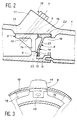
- la figure 1 représente un compresseur équipé de l'invention,
- la figure 2 représente un agrandissement de la figure 1 qui montre plus particulièrement l'agencement conforme à l'invention,
- et la figure 3 est une vue axiale des éléments composant la figure 2.
- FIG. 1 represents a compressor equipped with the invention,
- FIG. 2 represents an enlargement of FIG. 1 which shows more particularly the arrangement in accordance with the invention,
- and FIG. 3 is an axial view of the elements making up FIG. 2.
Le carter extérieur est une enveloppe légèrement conique désignée par 1 sur la figure 1 et qui peut être formée de parties assemblées entre elles. Le carter 1 entoure des éléments de virole 2, qui sont également sensiblement coniques, mis bout à bout et assemblés par des joints à emboîtement 3 pour former une seule virole continue et à peu près parallèle au carter 1. Chaque élément de virole 2 porte un étage d'aubes fixes 4 de stator ou de redressement. Un étage d'aubes mobiles 5 de rotor s'étend entre chaque paire d'étages d'aubes fixes 4.The outer casing is a slightly conical envelope designated by 1 in FIG. 1 and which can be formed from parts assembled together. The
Chaque élément de virole 2 est muni d'une nervure 6 qui s'étend à partir de lui vers l'extérieur en direction radiale pour toucher au carter 1 par son arête extérieure 7. A chaque nervure 6 est accolée une pièce d'étanchéité 8 caractéristique de l'invention et qui sera décrite plus loin. Chaque nervure 6 est enfin munie d'une semelle 9 externe circulaire et completée de place en place par un bloc 10 qui fait alors face à un autre bloc 11 correspondant à un renflement du carter 1 vers l'extérieur. Les blocs 10 et 11 sont traversés par des perçages qui viennent en prolongement et qu'un boulon 12 occupe. Les ensembles constitués par les éléments de virole 2, les nervures 6 et les semelles 9 sont alors solidement fixés au carter 1.Each
Les nervures 6 divisent le volume entre le carter 1 et la virole 2 en compartiments dans chacun desquels débouche un dispositif d'alimentation en gaz de réglage des jeux entre la portion de virole 2 et les étages d'aubes mobiles 5 associés à ces portions. Ces dispositifs ne font pas partie de l'invention. On se borne à représenter et à désigner par la référence 13 les orifices à travers le carter 1 qui débouchent chacun dans un compartiment respectif. Mais chaque nervure 6 est ajourée sur une grande partie de sa longueur, et l'arête 7 est formée de fragments interrompus. Les jours 14 (mieux visibles sur la figure 3) s'étendent sur l'essentiel de la hauteur des nervures 6 et jusqu'au carter 1 dans le sens radial de sorte que les nervures 6 ne touchent au carter 1 que par des portions assez hautes et étroites qui limitent beaucoup la chaleur transmise. Comme on le voit sur la figure 2, les nervures 6 sont munies près des éléments de virole 2 d'une surface d'appui 15 située dans un plan radial et orientée vers la pièce d'étancheité 8, et les semelles 9 comprennent une autre surface d'appui 16 appartenant au même plan. Le carter 1 est conçu avec une surface circulaire 17 sur laquelle s'appuient, dans le sens radial, la semelle 9 et une autre semelle 18 qui compose la pièce d'étanchéité 8 avec un jambage 19, et d'une surface de compression 20 qui s'étend dans un plan transversal et sert à comprimer la semelle 18 contre la surface d'appui 16 ; les deux surfaces 17 et 20 forment un redan dans le carter 1.The
Les pièces d'étanchéité 8 sont des anneaux sans interruptions sur la circonférence. Les jambages 19 sont composés d'une partie supérieure 21 qui s'étend à partir de la semelle 18 radialement, mais avec une inclinaison longitudinale vers la nervure 6 associée, et d'une portion d'extrémité 22 purement radiale qui termine la partie supérieure 21 et comporte une surface d'appui 23 qui est destinée à être pressée contre la surface d'appui 15 de la nervure 6. La portion d'extrémité 22 dépasse au moins partiellement de la semelle 18 dans le sens longitudinal quand la pièce d'étanchéité 8 est démontée, ce qu'on a figuré par les tirets. Quand le montage est entrepris, le serrage des boulons 12 provoque à la fois un déplacement longitudinal de la pièce d'étanchéité 8 vers la nervure 6, qui se traduit par un fléchissement élastique du jambage 19 quand les surfaces 15 et 23 viennent à se toucher et à frotter l'une contre l'autre, et un déplacement radial grace à la contraction exercée sur la semelle 18 par la surface 17. On en arrive à une situation où la pièce d'étanchéité 8 est fermement appuyée contre les surfaces 15 et 16 de la nervure 6 et contre les surfaces 17 et 20 du carter 1. Les surfaces 15, 17 et 20, de même que les surfaces de la pièce d'étanchéité 8 qui s'appuient sur elles, sont de faible rugosité pour interdire tout passage significatif de gaz entre les compartiments : elles peuvent par exemple être tournées.The sealing
L'axe X des boulons 12 a une inclinaison, comptée de la direction radiale dans un plan longitudinal, qui peut être de 40 ou 50° environ selon qu'on cherche à favoriser la compression axiale ou radiale, ce qui est une question particulière à chaque réalisation. Il est d'ailleurs possible de choisir une autre inclinaison.The axis X of the
Le montage des pièces d'étanchéité 8 ne soulève pas de difficultés particulières car elles peuvent être introduites par l'embouchure élargie du carter 1 conique. Les éléments de virole 2 sont ensuite montés et boulonnés.The mounting of the
Claims (3)
Applications Claiming Priority (2)
| Application Number | Priority Date | Filing Date | Title |
|---|---|---|---|
| FR9210278 | 1992-08-26 | ||
| FR9210278A FR2695164B1 (en) | 1992-08-26 | 1992-08-26 | Turbomachine provided with a device preventing a longitudinal circulation of gas around the stages of straightening vanes. |
Publications (2)
| Publication Number | Publication Date |
|---|---|
| EP0589736A1 true EP0589736A1 (en) | 1994-03-30 |
| EP0589736B1 EP0589736B1 (en) | 1996-04-03 |
Family
ID=9433022
Family Applications (1)
| Application Number | Title | Priority Date | Filing Date |
|---|---|---|---|
| EP93402092A Expired - Lifetime EP0589736B1 (en) | 1992-08-26 | 1993-08-25 | Turbomachine with a device for stopping axial gas flows at the periphery of stator stages |
Country Status (4)
| Country | Link |
|---|---|
| US (1) | US5320484A (en) |
| EP (1) | EP0589736B1 (en) |
| DE (1) | DE69302065T2 (en) |
| FR (1) | FR2695164B1 (en) |
Cited By (1)
| Publication number | Priority date | Publication date | Assignee | Title |
|---|---|---|---|---|
| US5616003A (en) * | 1993-10-27 | 1997-04-01 | Societe Nationale D'etude Et De Construction De Moteurs D'aviation "Snecma" | Turbine engine equipped with means for controlling the play between the rotor and stator |
Families Citing this family (9)
| Publication number | Priority date | Publication date | Assignee | Title |
|---|---|---|---|---|
| FR2794816B1 (en) * | 1999-06-10 | 2001-07-06 | Snecma | HIGH PRESSURE COMPRESSOR STATOR |
| EP1118806A1 (en) * | 2000-01-20 | 2001-07-25 | Siemens Aktiengesellschaft | Thermally charged wall structure and method to seal gaps in such a structure |
| FR2817285B1 (en) | 2000-11-30 | 2003-06-13 | Snecma Moteurs | STATOR INTERNAL OIL |
| DE10213402A1 (en) * | 2002-03-26 | 2003-12-24 | Mtu Aero Engines Gmbh | Arrangement for fastening struts serving as bearing supports for the rotor of an aircraft gas turbine to the housing structure of the aircraft gas turbine |
| DE60213621T2 (en) * | 2002-12-03 | 2007-03-08 | Techspace Aero S.A. | Seal for the low-pressure compressor of an aircraft engine |
| US7025563B2 (en) | 2003-12-19 | 2006-04-11 | United Technologies Corporation | Stator vane assembly for a gas turbine engine |
| FR2868125B1 (en) * | 2004-03-26 | 2006-07-21 | Snecma Moteurs Sa | TURBOMACHINE COMPRISING TWO SUBASSEMBLIES ASSEMBLED WITH AXIAL CONSTRAINTS |
| US9822693B2 (en) * | 2012-01-16 | 2017-11-21 | Borgwarner Inc. | Exhaust-gas turbocharger |
| CN110284929B (en) * | 2019-07-19 | 2021-10-22 | 中国航发沈阳发动机研究所 | Turbine cartridge receiver structure of obturaging |
Citations (5)
| Publication number | Priority date | Publication date | Assignee | Title |
|---|---|---|---|---|
| FR896166A (en) * | 1942-07-09 | 1945-02-14 | Wagner Hochdruck Dampfturbinen | Guide vane support for steam and gas turbines, especially for high pressures and high temperatures |
| GB961588A (en) * | 1960-02-05 | 1964-06-24 | Licentia Gmbh | A stationary-blade carrier for axial-flow turbines |
| US3376017A (en) * | 1964-09-25 | 1968-04-02 | English Electric Co Ltd | Turbines |
| FR2482661A1 (en) * | 1980-05-16 | 1981-11-20 | United Technologies Corp | FLOW DIRECTOR ASSEMBLY FOR A GAS TURBINE |
| FR2596115A1 (en) * | 1986-03-21 | 1987-09-25 | Rolls Royce | Improvement to retention means |
Family Cites Families (12)
| Publication number | Priority date | Publication date | Assignee | Title |
|---|---|---|---|---|
| FR2280791A1 (en) * | 1974-07-31 | 1976-02-27 | Snecma | IMPROVEMENTS IN ADJUSTING THE CLEARANCE BETWEEN THE BLADES AND THE STATOR OF A TURBINE |
| US4023919A (en) * | 1974-12-19 | 1977-05-17 | General Electric Company | Thermal actuated valve for clearance control |
| US4314793A (en) * | 1978-12-20 | 1982-02-09 | United Technologies Corporation | Temperature actuated turbine seal |
| US4318668A (en) * | 1979-11-01 | 1982-03-09 | United Technologies Corporation | Seal means for a gas turbine engine |
| US4431373A (en) * | 1980-05-16 | 1984-02-14 | United Technologies Corporation | Flow directing assembly for a gas turbine engine |
| US4426191A (en) * | 1980-05-16 | 1984-01-17 | United Technologies Corporation | Flow directing assembly for a gas turbine engine |
| US4416111A (en) * | 1981-02-25 | 1983-11-22 | The United States Of America As Represented By The Administrator Of The National Aeronautics And Space Administration | Air modulation apparatus |
| US4541775A (en) * | 1983-03-30 | 1985-09-17 | United Technologies Corporation | Clearance control in turbine seals |
| US4807433A (en) * | 1983-05-05 | 1989-02-28 | General Electric Company | Turbine cooling air modulation |
| US4720236A (en) * | 1984-12-21 | 1988-01-19 | United Technologies Corporation | Coolable stator assembly for a gas turbine engine |
| GB2236147B (en) * | 1989-08-24 | 1993-05-12 | Rolls Royce Plc | Gas turbine engine with turbine tip clearance control device and method of operation |
| US5100291A (en) * | 1990-03-28 | 1992-03-31 | General Electric Company | Impingement manifold |
-
1992
- 1992-08-26 FR FR9210278A patent/FR2695164B1/en not_active Expired - Fee Related
-
1993
- 1993-04-29 US US08/055,068 patent/US5320484A/en not_active Expired - Lifetime
- 1993-08-25 EP EP93402092A patent/EP0589736B1/en not_active Expired - Lifetime
- 1993-08-25 DE DE69302065T patent/DE69302065T2/en not_active Expired - Lifetime
Patent Citations (5)
| Publication number | Priority date | Publication date | Assignee | Title |
|---|---|---|---|---|
| FR896166A (en) * | 1942-07-09 | 1945-02-14 | Wagner Hochdruck Dampfturbinen | Guide vane support for steam and gas turbines, especially for high pressures and high temperatures |
| GB961588A (en) * | 1960-02-05 | 1964-06-24 | Licentia Gmbh | A stationary-blade carrier for axial-flow turbines |
| US3376017A (en) * | 1964-09-25 | 1968-04-02 | English Electric Co Ltd | Turbines |
| FR2482661A1 (en) * | 1980-05-16 | 1981-11-20 | United Technologies Corp | FLOW DIRECTOR ASSEMBLY FOR A GAS TURBINE |
| FR2596115A1 (en) * | 1986-03-21 | 1987-09-25 | Rolls Royce | Improvement to retention means |
Cited By (1)
| Publication number | Priority date | Publication date | Assignee | Title |
|---|---|---|---|---|
| US5616003A (en) * | 1993-10-27 | 1997-04-01 | Societe Nationale D'etude Et De Construction De Moteurs D'aviation "Snecma" | Turbine engine equipped with means for controlling the play between the rotor and stator |
Also Published As
| Publication number | Publication date |
|---|---|
| US5320484A (en) | 1994-06-14 |
| DE69302065D1 (en) | 1996-05-09 |
| EP0589736B1 (en) | 1996-04-03 |
| FR2695164B1 (en) | 1994-11-04 |
| FR2695164A1 (en) | 1994-03-04 |
| DE69302065T2 (en) | 1996-09-12 |
Similar Documents
| Publication | Publication Date | Title |
|---|---|---|
| EP1164253B1 (en) | Cooling system for the shroud of paired rotor blades | |
| EP0967364B1 (en) | Stator ring for the high-pressure turbine of a turbomachine | |
| CA2622116C (en) | High-pressure turbine of a turbomachine | |
| EP0589736B1 (en) | Turbomachine with a device for stopping axial gas flows at the periphery of stator stages | |
| US6592326B2 (en) | Connecting stator elements | |
| EP1811131B1 (en) | Set of fixed sectorised diffuser inserts for a turbomachine compressor | |
| FR2529947A2 (en) | AUBE WITH CERAMIC CARAPACE INTENDED FOR MOBILE AND FIXED TURBOMACHINE AUBING EQUIPMENT | |
| CA2868452C (en) | Turbine engine, such as a turbojet or a turboprop engine | |
| FR2858652A1 (en) | DEVICE FOR CONTROLLING PLAY IN A GAS TURBINE | |
| EP1265035A1 (en) | Double mounting of a ceramic matrix composite combustion chamber | |
| CA2882320A1 (en) | Turbine rotor for a turbomachine | |
| CA2925438C (en) | Rotary assembly for a turbomachine | |
| EP1265032A1 (en) | Ceramic matrix composite material gas turbine combustion chamber | |
| FR2835563A1 (en) | ARRANGEMENT FOR HANGING SECTORS IN A CIRCLE OF A CIRCLE OF A BLADE BEARING DISTRIBUTOR | |
| FR2577280A1 (en) | GAS TURBINE ENGINE | |
| FR2894281A1 (en) | TURBINE TURBINE WITH IMPROVED COOLING AND LIFETIME | |
| FR2919345A1 (en) | Cylindrical or truncated ring for e.g. jet prop engine, has internal slots housing internal blades between discharge ends of channels and internal longitudinal edges of radial surfaces, where blades extend on axial length of ring sectors | |
| FR2636373A1 (en) | DEVICE FOR ATTACHING ENVELOPED CROWN IN GAS TURBINES | |
| EP1580402B1 (en) | Turbomachine with two sub-assemblies being under axial pressure | |
| US20020127101A1 (en) | Stator vane for an axial flow turbine | |
| FR2851286A1 (en) | Turbine blade for turbo machine, has annular space between free end of liner and internal edge of vane to define leak zone for cool air where internal edge has cavity to create load loss in zone to reduce flow of cool air | |
| FR3082872A1 (en) | DEVICE FOR COOLING A TURBOMACHINE HOUSING | |
| WO2021186134A1 (en) | Turbine assembly, and gas turbine engine provided with such an assembly | |
| FR2534982A1 (en) | Control device for the tolerances of a high-pressure compressor | |
| FR2623243A1 (en) | GUIDE CROWN FOR A GAS TURBINE WITH AN INTERNAL RING, AN EXTERNAL RING ONE OF WHICH IS SEPARATELY DISPOSABLE AND LIKELY TO BE MOVED SEPARATELY |
Legal Events
| Date | Code | Title | Description |
|---|---|---|---|
| PUAI | Public reference made under article 153(3) epc to a published international application that has entered the european phase |
Free format text: ORIGINAL CODE: 0009012 |
|
| 17P | Request for examination filed |
Effective date: 19930925 |
|
| AK | Designated contracting states |
Kind code of ref document: A1 Designated state(s): DE FR GB |
|
| RIN1 | Information on inventor provided before grant (corrected) |
Inventor name: WALKER, ROGER CLAYTON Inventor name: RECEVEUR, GERARD Inventor name: NAUDET, JACKY, SERGE Inventor name: MOURLAN, JEAN-PIERRE, ANDRE JOSEPH Inventor name: MAREY, DANIEL, JEAN Inventor name: GLYNN, CHRISTOPHER CHARLES Inventor name: DEBENEIX, PIERRE Inventor name: CHARBONNEL, JEAN-LOUIS |
|
| 17Q | First examination report despatched |
Effective date: 19950828 |
|
| GRAA | (expected) grant |
Free format text: ORIGINAL CODE: 0009210 |
|
| AK | Designated contracting states |
Kind code of ref document: B1 Designated state(s): DE FR GB |
|
| REF | Corresponds to: |
Ref document number: 69302065 Country of ref document: DE Date of ref document: 19960509 |
|
| GBT | Gb: translation of ep patent filed (gb section 77(6)(a)/1977) |
Effective date: 19960507 |
|
| PLBE | No opposition filed within time limit |
Free format text: ORIGINAL CODE: 0009261 |
|
| STAA | Information on the status of an ep patent application or granted ep patent |
Free format text: STATUS: NO OPPOSITION FILED WITHIN TIME LIMIT |
|
| 26N | No opposition filed | ||
| REG | Reference to a national code |
Ref country code: GB Ref legal event code: IF02 |
|
| REG | Reference to a national code |
Ref country code: FR Ref legal event code: TP Ref country code: FR Ref legal event code: CD |
|
| REG | Reference to a national code |
Ref country code: FR Ref legal event code: CD |
|
| PGFP | Annual fee paid to national office [announced via postgrant information from national office to epo] |
Ref country code: GB Payment date: 20110728 Year of fee payment: 19 Ref country code: DE Payment date: 20110803 Year of fee payment: 19 |
|
| PGFP | Annual fee paid to national office [announced via postgrant information from national office to epo] |
Ref country code: FR Payment date: 20120822 Year of fee payment: 20 |
|
| GBPC | Gb: european patent ceased through non-payment of renewal fee |
Effective date: 20120825 |
|
| PG25 | Lapsed in a contracting state [announced via postgrant information from national office to epo] |
Ref country code: GB Free format text: LAPSE BECAUSE OF NON-PAYMENT OF DUE FEES Effective date: 20120825 Ref country code: DE Free format text: LAPSE BECAUSE OF NON-PAYMENT OF DUE FEES Effective date: 20130301 |
|
| REG | Reference to a national code |
Ref country code: DE Ref legal event code: R119 Ref document number: 69302065 Country of ref document: DE Effective date: 20130301 |