EP0589736A1 - Turbomaschine mit einer Vorrichtung zur Vermeidung von axialen Gasströmen um Statorstufen - Google Patents
Turbomaschine mit einer Vorrichtung zur Vermeidung von axialen Gasströmen um Statorstufen Download PDFInfo
- Publication number
- EP0589736A1 EP0589736A1 EP19930402092 EP93402092A EP0589736A1 EP 0589736 A1 EP0589736 A1 EP 0589736A1 EP 19930402092 EP19930402092 EP 19930402092 EP 93402092 A EP93402092 A EP 93402092A EP 0589736 A1 EP0589736 A1 EP 0589736A1
- Authority
- EP
- European Patent Office
- Prior art keywords
- casing
- sole
- ferrule
- turbomachine
- ribs
- Prior art date
- Legal status (The legal status is an assumption and is not a legal conclusion. Google has not performed a legal analysis and makes no representation as to the accuracy of the status listed.)
- Granted
Links
- 238000007789 sealing Methods 0.000 claims abstract description 15
- 230000006835 compression Effects 0.000 claims abstract description 9
- 238000007906 compression Methods 0.000 claims abstract description 9
- 230000000284 resting effect Effects 0.000 abstract 1
- 238000006073 displacement reaction Methods 0.000 description 2
- 230000000712 assembly Effects 0.000 description 1
- 238000000429 assembly Methods 0.000 description 1
- 238000005452 bending Methods 0.000 description 1
- 238000007664 blowing Methods 0.000 description 1
- 230000008602 contraction Effects 0.000 description 1
- 238000001816 cooling Methods 0.000 description 1
- 239000012634 fragment Substances 0.000 description 1
- 238000010438 heat treatment Methods 0.000 description 1
Images

Classifications
-
- F—MECHANICAL ENGINEERING; LIGHTING; HEATING; WEAPONS; BLASTING
- F01—MACHINES OR ENGINES IN GENERAL; ENGINE PLANTS IN GENERAL; STEAM ENGINES
- F01D—NON-POSITIVE DISPLACEMENT MACHINES OR ENGINES, e.g. STEAM TURBINES
- F01D25/00—Component parts, details, or accessories, not provided for in, or of interest apart from, other groups
- F01D25/24—Casings; Casing parts, e.g. diaphragms, casing fastenings
- F01D25/26—Double casings; Measures against temperature strain in casings
-
- F—MECHANICAL ENGINEERING; LIGHTING; HEATING; WEAPONS; BLASTING
- F01—MACHINES OR ENGINES IN GENERAL; ENGINE PLANTS IN GENERAL; STEAM ENGINES
- F01D—NON-POSITIVE DISPLACEMENT MACHINES OR ENGINES, e.g. STEAM TURBINES
- F01D11/00—Preventing or minimising internal leakage of working-fluid, e.g. between stages
- F01D11/005—Sealing means between non relatively rotating elements
Definitions
- the invention relates to a turbomachine equipped with a device preventing the longitudinal or axial circulation of gas around the stages of vanes for straightening the flow in the machine.
- the stator of many turbomachinery consists of a double envelope: an outer casing which surrounds a ferrule formed of elements assembled together and to which the blades of the rectifier stages are fixed.
- the ferrule elements are screwed to the casing and provided with circular ribs of radial extension which maintain the spacing between the ferrule and the casing to which they touch by their end edge.
- these ribs are responsible for a significant loss of heat to the outside due to their good thermal conductivity, they are perforated so as to only touch the casing by portions of circumference.
- the invention represents a possible and particularly simple solution for this. It relates to a turbomachine comprising a casing surrounding ferrule elements to which blades of rectifier stages are fixed, the ferrule elements being connected to the casing by bolts, characterized in that the ferrule elements are provided with ribs which separate them from the casing and extend to the casing, the ribs being provided with days so as to touch the casing only by portions of circumference, and in that it comprises annular sealing parts composed of a circular sole and of a leg extending substantially radially inward from the sole to a bearing surface extending in a radial plane of an associated rib, the leg covering the days of the rib and rubbing on the bearing surface, the casing being provided for each sealing part with a step delimited by a radial compression surface of the sole and a longitudinal compression surface of the melle against the associated rib, and the bolts extend with a longitudinal inclination capable of causing
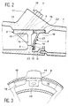
- the outer casing is a slightly conical envelope designated by 1 in FIG. 1 and which can be formed from parts assembled together.
- the casing 1 surrounds ferrule elements 2, which are also substantially conical, placed end to end and assembled by interlocking seals 3 to form a single continuous ferrule and approximately parallel to the casing 1.
- Each ferrule element 2 carries a stationary stator or stator vane stage 4.
- a stage of movable rotor blades 5 extends between each pair of stages of fixed blades 4.
- Each ferrule element 2 is provided with a rib 6 which extends from it outwards in a radial direction to touch the casing 1 by its outer edge 7. At each rib 6 is joined a sealing piece 8 characteristic of the invention and which will be described later.
- Each rib 6 is finally provided with a circular outer sole 9 and completed from place to place by a block 10 which then faces another block 11 corresponding to a bulge of the casing 1 outwards.
- the blocks 10 and 11 are crossed by holes which come in extension and which a bolt 12 occupies.
- the assemblies constituted by the shell elements 2, the ribs 6 and the flanges 9 are then securely fixed to the casing 1.
- the ribs 6 divide the volume between the casing 1 and the shell 2 into compartments into each of which opens a gas supply device. for adjusting the clearances between the ferrule portion 2 and the stages of movable blades 5 associated with these portions. These devices are not part of the invention.
- each rib 6 is perforated over a large part of its length, and the edge 7 is formed of interrupted fragments. Days 14 (better visible in FIG. 3) extend over most of the height of the ribs 6 and up to the casing 1 in the radial direction so that the ribs 6 only touch the casing 1 by fairly large portions. tall and narrow which greatly limit the heat transmitted.
- the ribs 6 are provided near the ferrule elements 2 with a bearing surface 15 situated in a radial plane and oriented towards the sealing part 8, and the flanges 9 comprise another bearing surface 16 belonging to the same plane.
- the casing 1 is designed with a circular surface 17 on which the sole 9 rests in a radial direction and another sole 18 which forms the sealing part 8 with a leg 19, and with a compression surface 20 which extends in a transverse plane and serves to compress the sole 18 against the bearing surface 16; the two surfaces 17 and 20 form a step in the casing 1.
- the sealing parts 8 are rings without interruptions on the circumference.
- the legs 19 are composed of an upper part 21 which extends from the sole 18 radially, but with a longitudinal inclination towards the associated rib 6, and of a purely radial end portion 22 which terminates the upper part 21 and has a bearing surface 23 which is intended to be pressed against the bearing surface 15 of the rib 6.
- the portion end 22 protrudes at least partially from the sole 18 in the longitudinal direction when the sealing part 8 is disassembled, which is shown by the dashes.
- the tightening of the bolts 12 causes both a longitudinal displacement of the sealing part 8 towards the rib 6, which results in an elastic bending of the leg 19 when the surfaces 15 and 23 come to touch and to rub against each other, and a radial displacement by virtue of the contraction exerted on the sole 18 by the surface 17.
- the surfaces 15, 17 and 20, as well as the surfaces of the sealing part 8 which rest on them, are of low roughness to prevent any significant passage of gas between the compartments: they can for example be rotated.
- the axis X of the bolts 12 has an inclination, counted from the radial direction in a longitudinal plane, which can be approximately 40 or 50 ° depending on whether one seeks to promote axial or radial compression, which is a particular question to each achievement. It is also possible to choose another inclination.
- the mounting of the sealing parts 8 does not raise any particular difficulties because they can be introduced through the enlarged mouth of the conical casing 1.
- the shell elements 2 are then mounted and bolted.
Landscapes
- Engineering & Computer Science (AREA)
- Mechanical Engineering (AREA)
- General Engineering & Computer Science (AREA)
- Structures Of Non-Positive Displacement Pumps (AREA)
- Turbine Rotor Nozzle Sealing (AREA)
Applications Claiming Priority (2)
| Application Number | Priority Date | Filing Date | Title |
|---|---|---|---|
| FR9210278 | 1992-08-26 | ||
| FR9210278A FR2695164B1 (fr) | 1992-08-26 | 1992-08-26 | Turbomachine munie d'un dispositif empêchant une circulation longitudinale de gaz autour des étages d'aubes de redressement. |
Publications (2)
| Publication Number | Publication Date |
|---|---|
| EP0589736A1 true EP0589736A1 (de) | 1994-03-30 |
| EP0589736B1 EP0589736B1 (de) | 1996-04-03 |
Family
ID=9433022
Family Applications (1)
| Application Number | Title | Priority Date | Filing Date |
|---|---|---|---|
| EP93402092A Expired - Lifetime EP0589736B1 (de) | 1992-08-26 | 1993-08-25 | Turbomaschine mit einer Vorrichtung zur Vermeidung von axialen Gasströmen um Statorstufen |
Country Status (4)
| Country | Link |
|---|---|
| US (1) | US5320484A (de) |
| EP (1) | EP0589736B1 (de) |
| DE (1) | DE69302065T2 (de) |
| FR (1) | FR2695164B1 (de) |
Cited By (2)
| Publication number | Priority date | Publication date | Assignee | Title |
|---|---|---|---|---|
| US5616003A (en) * | 1993-10-27 | 1997-04-01 | Societe Nationale D'etude Et De Construction De Moteurs D'aviation "Snecma" | Turbine engine equipped with means for controlling the play between the rotor and stator |
| RU2172441C2 (ru) * | 1998-11-19 | 2001-08-20 | Сосьете Насьональ Д'Этюд Э Де Констрюксьон Де Мотер Д`Авиасьон "Снекма" | Устройство уплотнения с пластиной |
Families Citing this family (9)
| Publication number | Priority date | Publication date | Assignee | Title |
|---|---|---|---|---|
| FR2794816B1 (fr) * | 1999-06-10 | 2001-07-06 | Snecma | Stator de compresseur a haute pression |
| EP1118806A1 (de) * | 2000-01-20 | 2001-07-25 | Siemens Aktiengesellschaft | Thermisch belastbare Wand und Verfahren zur Abdichtung eines Spaltes in einer thermisch belasteten Wand |
| FR2817285B1 (fr) | 2000-11-30 | 2003-06-13 | Snecma Moteurs | Virole interne de stator |
| DE10213402A1 (de) * | 2002-03-26 | 2003-12-24 | Mtu Aero Engines Gmbh | Anordnung zur Befestigung von als Lagerträger für den Rotor einer Fluggasturbine dienenden Streben an der Gehäusestruktur der Fluggasturbine |
| EP1426560B1 (de) * | 2002-12-03 | 2006-08-02 | Techspace Aero S.A. | Dichtung für den Niederdruckverdichter eines Flugtriebwerks |
| US7025563B2 (en) | 2003-12-19 | 2006-04-11 | United Technologies Corporation | Stator vane assembly for a gas turbine engine |
| FR2868125B1 (fr) * | 2004-03-26 | 2006-07-21 | Snecma Moteurs Sa | Turbomachine comprenant deux sous-ensembles assembles sous contrainte axiale |
| DE112013000319B4 (de) * | 2012-01-16 | 2021-05-20 | Borgwarner Inc. | Abgasturbolader |
| CN110284929B (zh) * | 2019-07-19 | 2021-10-22 | 中国航发沈阳发动机研究所 | 一种涡轮机匣封严结构 |
Citations (5)
| Publication number | Priority date | Publication date | Assignee | Title |
|---|---|---|---|---|
| FR896166A (fr) * | 1942-07-09 | 1945-02-14 | Wagner Hochdruck Dampfturbinen | Support d'aubes directrices pour turbines à vapeur et à gaz, en particulier pour hautes pressions et températures élevées |
| GB961588A (en) * | 1960-02-05 | 1964-06-24 | Licentia Gmbh | A stationary-blade carrier for axial-flow turbines |
| US3376017A (en) * | 1964-09-25 | 1968-04-02 | English Electric Co Ltd | Turbines |
| FR2482661A1 (fr) * | 1980-05-16 | 1981-11-20 | United Technologies Corp | Assemblage directeur d'ecoulement pour une turbine a gaz |
| FR2596115A1 (fr) * | 1986-03-21 | 1987-09-25 | Rolls Royce | Perfectionnement aux moyens de retenue |
Family Cites Families (12)
| Publication number | Priority date | Publication date | Assignee | Title |
|---|---|---|---|---|
| FR2280791A1 (fr) * | 1974-07-31 | 1976-02-27 | Snecma | Perfectionnements au reglage du jeu entre les aubes et le stator d'une turbine |
| US4023919A (en) * | 1974-12-19 | 1977-05-17 | General Electric Company | Thermal actuated valve for clearance control |
| US4314793A (en) * | 1978-12-20 | 1982-02-09 | United Technologies Corporation | Temperature actuated turbine seal |
| US4318668A (en) * | 1979-11-01 | 1982-03-09 | United Technologies Corporation | Seal means for a gas turbine engine |
| US4426191A (en) * | 1980-05-16 | 1984-01-17 | United Technologies Corporation | Flow directing assembly for a gas turbine engine |
| US4431373A (en) * | 1980-05-16 | 1984-02-14 | United Technologies Corporation | Flow directing assembly for a gas turbine engine |
| US4416111A (en) * | 1981-02-25 | 1983-11-22 | The United States Of America As Represented By The Administrator Of The National Aeronautics And Space Administration | Air modulation apparatus |
| US4541775A (en) * | 1983-03-30 | 1985-09-17 | United Technologies Corporation | Clearance control in turbine seals |
| US4807433A (en) * | 1983-05-05 | 1989-02-28 | General Electric Company | Turbine cooling air modulation |
| US4720236A (en) * | 1984-12-21 | 1988-01-19 | United Technologies Corporation | Coolable stator assembly for a gas turbine engine |
| GB2236147B (en) * | 1989-08-24 | 1993-05-12 | Rolls Royce Plc | Gas turbine engine with turbine tip clearance control device and method of operation |
| US5100291A (en) * | 1990-03-28 | 1992-03-31 | General Electric Company | Impingement manifold |
-
1992
- 1992-08-26 FR FR9210278A patent/FR2695164B1/fr not_active Expired - Fee Related
-
1993
- 1993-04-29 US US08/055,068 patent/US5320484A/en not_active Expired - Lifetime
- 1993-08-25 EP EP93402092A patent/EP0589736B1/de not_active Expired - Lifetime
- 1993-08-25 DE DE69302065T patent/DE69302065T2/de not_active Expired - Lifetime
Patent Citations (5)
| Publication number | Priority date | Publication date | Assignee | Title |
|---|---|---|---|---|
| FR896166A (fr) * | 1942-07-09 | 1945-02-14 | Wagner Hochdruck Dampfturbinen | Support d'aubes directrices pour turbines à vapeur et à gaz, en particulier pour hautes pressions et températures élevées |
| GB961588A (en) * | 1960-02-05 | 1964-06-24 | Licentia Gmbh | A stationary-blade carrier for axial-flow turbines |
| US3376017A (en) * | 1964-09-25 | 1968-04-02 | English Electric Co Ltd | Turbines |
| FR2482661A1 (fr) * | 1980-05-16 | 1981-11-20 | United Technologies Corp | Assemblage directeur d'ecoulement pour une turbine a gaz |
| FR2596115A1 (fr) * | 1986-03-21 | 1987-09-25 | Rolls Royce | Perfectionnement aux moyens de retenue |
Cited By (2)
| Publication number | Priority date | Publication date | Assignee | Title |
|---|---|---|---|---|
| US5616003A (en) * | 1993-10-27 | 1997-04-01 | Societe Nationale D'etude Et De Construction De Moteurs D'aviation "Snecma" | Turbine engine equipped with means for controlling the play between the rotor and stator |
| RU2172441C2 (ru) * | 1998-11-19 | 2001-08-20 | Сосьете Насьональ Д'Этюд Э Де Констрюксьон Де Мотер Д`Авиасьон "Снекма" | Устройство уплотнения с пластиной |
Also Published As
| Publication number | Publication date |
|---|---|
| US5320484A (en) | 1994-06-14 |
| DE69302065D1 (de) | 1996-05-09 |
| FR2695164B1 (fr) | 1994-11-04 |
| DE69302065T2 (de) | 1996-09-12 |
| EP0589736B1 (de) | 1996-04-03 |
| FR2695164A1 (fr) | 1994-03-04 |
Similar Documents
| Publication | Publication Date | Title |
|---|---|---|
| EP0589736B1 (de) | Turbomaschine mit einer Vorrichtung zur Vermeidung von axialen Gasströmen um Statorstufen | |
| USRE43611E1 (en) | Connecting stator elements | |
| EP1164253B1 (de) | Kühlungssystem für die Abdeckplatten von Rotorschaufelpaaren | |
| EP0967364B1 (de) | Statorring für die Hochdruckturbine einer Turbomachine | |
| CA2622116C (fr) | Turbine haute-pression d'une turbomachine | |
| EP1811131B1 (de) | Anordnung von Statorsektoren für einen Verdichter eines Turbotriebwerks | |
| FR2829176A1 (fr) | Carter de stator de turbomachine | |
| FR2529947A2 (fr) | Aube a carapace en ceramique destinee a l'equipement des aubages mobile et fixe de turbomachines | |
| FR2858652A1 (fr) | Dispositif de controle de jeu dans une turbine a gaz | |
| CA2725864C (fr) | Turbine haute pression d'une turbomachine avec montage ameliore du boitier de pilotage des jeux radiaux d'aubes mobiles | |
| FR2580033A1 (en) | Elastically suspended turbine ring for a turbine machine | |
| EP1265035A1 (de) | Doppelbefestigung einer Turbinenbrennkammer aus keramischem Matrix-Verbundwerkstoff | |
| EP1265032A1 (de) | Gasturbinenbrennkammer aus Verbundwerkstoff mit keramischer Matrix | |
| CA2925438C (fr) | Ensemble rotatif pour turbomachine | |
| EP4121635B1 (de) | Anordnung für turbine und gasturbinentriebwerk mit einer solchen anordnung | |
| FR2835563A1 (fr) | Agencement d'accrochage de secteurs en arc de cercle de distributeur porteur d'aubes | |
| FR2636373A1 (fr) | Dispositif pour fixer une couronne enveloppe dans des turbines a gaz | |
| CA2641438C (fr) | Aube refroidie de turbomachine | |
| FR2851286A1 (fr) | Aubes de turbine refroidie a fuite d'air de refroidissement reduite | |
| FR2623243A1 (fr) | Couronne directrice pour une turbine a gaz avec un anneau interne, un anneau externe dont l'un est dispose separement et susceptible d'etre deplace separement | |
| EP4010564B1 (de) | Anordnung zur halterung eines verteilers einer kühlungsvorrichtung eines turbinengehäuses einer turbomaschine | |
| FR2849104A1 (fr) | Collecteur d'echappement de vehicule automobile comportant une bride de support d'un composant | |
| FR2894281A1 (fr) | Aube de turbine a refroidissement et a duree de vie ameliores | |
| KR19990029031A (ko) | 증기 터빈의 배기 가스 연결부용 부품 | |
| FR2672943A1 (fr) | Compresseur de turbomachine equipe d'un dispositif de prelevement d'air. |
Legal Events
| Date | Code | Title | Description |
|---|---|---|---|
| PUAI | Public reference made under article 153(3) epc to a published international application that has entered the european phase |
Free format text: ORIGINAL CODE: 0009012 |
|
| 17P | Request for examination filed |
Effective date: 19930925 |
|
| AK | Designated contracting states |
Kind code of ref document: A1 Designated state(s): DE FR GB |
|
| RIN1 | Information on inventor provided before grant (corrected) |
Inventor name: WALKER, ROGER CLAYTON Inventor name: RECEVEUR, GERARD Inventor name: NAUDET, JACKY, SERGE Inventor name: MOURLAN, JEAN-PIERRE, ANDRE JOSEPH Inventor name: MAREY, DANIEL, JEAN Inventor name: GLYNN, CHRISTOPHER CHARLES Inventor name: DEBENEIX, PIERRE Inventor name: CHARBONNEL, JEAN-LOUIS |
|
| 17Q | First examination report despatched |
Effective date: 19950828 |
|
| GRAA | (expected) grant |
Free format text: ORIGINAL CODE: 0009210 |
|
| AK | Designated contracting states |
Kind code of ref document: B1 Designated state(s): DE FR GB |
|
| REF | Corresponds to: |
Ref document number: 69302065 Country of ref document: DE Date of ref document: 19960509 |
|
| GBT | Gb: translation of ep patent filed (gb section 77(6)(a)/1977) |
Effective date: 19960507 |
|
| PLBE | No opposition filed within time limit |
Free format text: ORIGINAL CODE: 0009261 |
|
| STAA | Information on the status of an ep patent application or granted ep patent |
Free format text: STATUS: NO OPPOSITION FILED WITHIN TIME LIMIT |
|
| 26N | No opposition filed | ||
| REG | Reference to a national code |
Ref country code: GB Ref legal event code: IF02 |
|
| REG | Reference to a national code |
Ref country code: FR Ref legal event code: TP Ref country code: FR Ref legal event code: CD |
|
| REG | Reference to a national code |
Ref country code: FR Ref legal event code: CD |
|
| PGFP | Annual fee paid to national office [announced via postgrant information from national office to epo] |
Ref country code: GB Payment date: 20110728 Year of fee payment: 19 Ref country code: DE Payment date: 20110803 Year of fee payment: 19 |
|
| PGFP | Annual fee paid to national office [announced via postgrant information from national office to epo] |
Ref country code: FR Payment date: 20120822 Year of fee payment: 20 |
|
| GBPC | Gb: european patent ceased through non-payment of renewal fee |
Effective date: 20120825 |
|
| PG25 | Lapsed in a contracting state [announced via postgrant information from national office to epo] |
Ref country code: GB Free format text: LAPSE BECAUSE OF NON-PAYMENT OF DUE FEES Effective date: 20120825 Ref country code: DE Free format text: LAPSE BECAUSE OF NON-PAYMENT OF DUE FEES Effective date: 20130301 |
|
| REG | Reference to a national code |
Ref country code: DE Ref legal event code: R119 Ref document number: 69302065 Country of ref document: DE Effective date: 20130301 |