EP0589447B1 - Verfahren zur Vereinigung und Trennung mehrerer Netzwerke - Google Patents
Verfahren zur Vereinigung und Trennung mehrerer Netzwerke Download PDFInfo
- Publication number
- EP0589447B1 EP0589447B1 EP93115343A EP93115343A EP0589447B1 EP 0589447 B1 EP0589447 B1 EP 0589447B1 EP 93115343 A EP93115343 A EP 93115343A EP 93115343 A EP93115343 A EP 93115343A EP 0589447 B1 EP0589447 B1 EP 0589447B1
- Authority
- EP
- European Patent Office
- Prior art keywords
- network
- information
- system definition
- definition information
- address
- Prior art date
- Legal status (The legal status is an assumption and is not a legal conclusion. Google has not performed a legal analysis and makes no representation as to the accuracy of the status listed.)
- Expired - Lifetime
Links
Images


Classifications
-
- H—ELECTRICITY
- H04—ELECTRIC COMMUNICATION TECHNIQUE
- H04L—TRANSMISSION OF DIGITAL INFORMATION, e.g. TELEGRAPHIC COMMUNICATION
- H04L41/00—Arrangements for maintenance, administration or management of data switching networks, e.g. of packet switching networks
-
- H—ELECTRICITY
- H04—ELECTRIC COMMUNICATION TECHNIQUE
- H04L—TRANSMISSION OF DIGITAL INFORMATION, e.g. TELEGRAPHIC COMMUNICATION
- H04L12/00—Data switching networks
- H04L12/28—Data switching networks characterised by path configuration, e.g. LAN [Local Area Networks] or WAN [Wide Area Networks]
- H04L12/46—Interconnection of networks
-
- H—ELECTRICITY
- H04—ELECTRIC COMMUNICATION TECHNIQUE
- H04L—TRANSMISSION OF DIGITAL INFORMATION, e.g. TELEGRAPHIC COMMUNICATION
- H04L41/00—Arrangements for maintenance, administration or management of data switching networks, e.g. of packet switching networks
- H04L41/08—Configuration management of networks or network elements
-
- H—ELECTRICITY
- H04—ELECTRIC COMMUNICATION TECHNIQUE
- H04L—TRANSMISSION OF DIGITAL INFORMATION, e.g. TELEGRAPHIC COMMUNICATION
- H04L9/00—Cryptographic mechanisms or cryptographic arrangements for secret or secure communications; Network security protocols
- H04L9/40—Network security protocols
Definitions
- the present invention generally relates to a communications system including a plurality of networks, and more particularly to a method for joining such networks and seceding therefrom.
- a communications system having a plurality of networks coupled to each other. Each communications network is allowed to communicate with one or a plurality of remote communications networks which are previously registered. If a communications network generates a request to communicate with (join) a remote communications network which has not been registered, a network system address indicating the above communications network is registered in the remote communications network, and a network system address indicating the remote communications network is registered in the communications network which has generated the above request.
- the network system address indicating the communications network having the above request is deleted from the remote communications network, and the network system address indicating the remote communications network is also deleted from the communications network having the above request.
- the registration and seceding processes are manually carried out in a state in which communications services provided by the communications networks being considered are interrupted.
- EP-A-0 474 427 discloses a method according to the preamble of claim 1. That is, each network is assigned a common network address and a second network address in order to exchange messages with another network. Each network is served by a LAN access module (LAM). At the time of forming a request message from an originating network, the associated LAM assigns the second address so that a potential recipient may identify the originating network, and subsequently assigns to the destination network a destination address, both addresses being stored in a routing table. Each LAM stores its own routing table in order to track addresses assigned and received.
- LAM LAN access module
- the above method comprises the step of (d) registering, at the second one of the communications networks indicated by the second address information, the first address information in a remote system definition information together with the management number, the first address information registered in the third system definition information indicating that the second one of the communications networks is allowed to communicate with the first one of the communications networks.
- the above method comprises the steps of:
- the above method comprises the step of: (e) deleting the second address information and the management number from the third system definition information when the first one of the communications networks stops a communication with the second one of the communications networks.
- Fig. 1 is a block diagram of a communications system having a plurality of communications networks NW1, NW2, NW3, NW4 and NW5.
- the communications network NW1 is connected to the communications networks NW2 through NW5 by means of communications media, such as cables.
- the communications networks NW1 through NW5 respectively form their own systems.
- the communications networks NW1 through NW5 have respective host devices HST1 through HST5, to which terminals TE1 through TE5 are respectively connected. In practice, a plurality of terminals are accommodated in the networks NW1 through NW5.
- Each of the communications networks manages its own system definition information 1 as shown in Fig. 2.
- the information shown in Fig. 2 is information managed by the host device HST1 of the communications network NW1.
- Each of the other host devices HST2 through HST5 of the communications networks NW2 through NW5 manages its own system definition information in the same way as the host device HST1.
- the network system addresses registered in the own system definition information 1 managed by the host device HST1 indicate the host devices (networks) that the host device HST1 (network NW1) joins and requests to communicate with.
- the system definition information 1 managed by the host device HST1 of the network NW1 includes an information item including a pointer, a management number 3 and a network system address (NSAP).
- the pointer is used to serially link items contained in the system definition information 1, as shown in Fig. 2.
- the information items can be formed for the respective communications networks NW1 through NW5.
- the information item shown on the leftmost side of Fig. 2 relates to the network NW1, and the information item next to the above item relates to the network NW2.
- the pointer of the information item relating to the network NW1 indicates the beginning of the information item relating to the network NW2.
- the management number 3 is serially assigned to the information items.
- the information items of the networks NW1, NW2 and NW4 are assigned management numbers 0, 1 and 2, respectively.
- the network system addresses nsap1, nsap2, nsap3, nsap4, ..., nsapn (n is an integer equal to 5 in the communications system shown in Fig. 1) are assigned to the communications networks NW1 through NW5.
- Each of the host devices HST1 through HST5 of the communications networks NW1 through NW5 manages, using the above-mentioned management number, the network system addresses of other remote networks as remote system definition information 2 shown in Fig. 2.
- the information 2 shown in Fig. 2 is information managed by the host computer HST1 of the network NW1 and is related to the communications network NW2.
- the remote system definition information 2 managed by the host device HST1 includes a host address number of the network system address NSAP.
- the network system address is nsap2
- the host address number is 1, which is the management number related to the communications network NW2 and managed by the host device HST1 of the network NW1.
- the network addresses registered in the remote system definition information 2 and managed by the host device HST1 indicate the host devices (networks) that the host device HST (network NW1) is capable of communicating with.
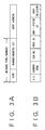
- Fig. 3A shows a format of the network system address NSAP of each of the host devices HST1 of the networks NW1 through NW5.
- the network system address NSAP includes information indicating the network type and the network identification number, and node addresses.
- the network type is, for example, a LAN (Local Area Network) or a WAN (Wide Area Network).
- the network identification number indicates the corresponding communications network.
- the node addresses indicate the addresses of nodes connected to the communications network related to the host device managing the network system address NSAP shown in Fig. 3A.
- Fig. 3B shows the network system address NSAP according to the E. 164 format.
- the E. 164 format of the network system address NSAP includes:
- the host device HST1 of the network NW1 stores the system definition information items of the other networks with which the network NW1 requests to communicate. A description will now be given, with reference to Figs. 4, 5 and 6, of a case where the host HST1 of the network NW1 generates a request to communicate with the host device ST2 of the network NW2 and the host device HST4 of the network NW4 when the host device HST1 is communicating with the terminal TE1.
- the host device HST1 of the network NW1 communicates with terminal TE1 accommodated in the network NW1 in step S1.
- the host device HST1 adds the network system address nsap2 of the network NW2 to the system definition information 1 managed by the host device HST1, as indicated by [1] in Fig. 6.
- the system definition information managed by the host device HST1 includes information concerning its own network NW1.
- the host device HST1 creates system information concerning the remote network NW2, as indicated by [2] shown in Fig. 6, and the host device HST2 creates system information concerning the remote network NW1, as indicated by [3] shown in Fig. 6.
- the created system information concerning the network NW1 (host device HST1) is registered in the remote system definition information 2 managed by the host device HST2.
- step S4 the host device HST1 activates the system definition information concerning the network NW2, and the host device HST2 activates the system definition information concerning the network NW1.
- the host device HST1 becomes capable of communicating with the host device HST2, and the host device HST2 becomes capable of communicating with the host device HST1. That is, the host device HST1 has joined the network NW2.
- step S5 the host device HST1 adds the network system address nsap4 of the network NW4 to the system definition information 1 managed by the host device HST1, as indicated by [4] shown in Fig. 6.
- step S6 the host device HST1 creates system information concerning the remote network NW4, as indicated by [5] shown in Fig. 6, and the host device HST4 creates system information concerning the remote network NW1, as indicated by [6] shown therein.
- the created system information concerning the remote network NW4 is registered in the remote system definition 2 managed by the host device HST1.
- the created system information concerning the network NW1 (host device HST1) is registered in the remote system definition information 2 managed by the host device HST4.
- step S7 the host device HST1 activates the system definition information concerning the network NW4, and the host device HST4 activates the system definition information concerning the network NW1.
- the host device HST1 becomes capable of communicating with the host device HST4, and the host device HST4 becomes capable of communicating with the host device HST1. That is, the host device HST1 has joined the network NW4, and the host device HST4 has joined the network NW1.
- the system definition information concerning the host device HST2 is registered in the remote system definition information 2 managed by the host system HST4. Further, as indicated by [7] shown in Fig. 6, the system definition information concerning the host device HST4 is registered in the remote system definition information 2 managed by the host system HST2.
- step S8 communications among the host devices HST1, HST2 and HST4 take place.
- the host devices HST1, HST2 and HST4 mutually create their own system definition information 1 and the remote system definition information 2 and activate the information 1 and information 2.
- the host devices HST1, HST2 and HST4 it becomes possible for the host devices HST1, HST2 and HST4 to communicate with one another.
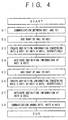
- Fig. 5 is a flowchart of a process for adding the network system address NSAP to the system definition information.
- the process can be manually or automatically performed.
- an operator of the host device HST1 of the network NW1 inputs a command to the host device HST1 via a keyboard or the like, and inputs a desired network system address NSAP and a management number corresponding to the desired network system address NSAP.
- the operator inputs the network system address nsap2.
- the management number may be automatically and assigned in response to the input of the network system address nsap2.
- management number "1" is assigned to the network system address nsap2.
- step S12 it is determined whether or not a network system address (NSAP) storage area corresponding to the network system address input in step S11 has been captured.
- a network system address storage area is indicated by an oval.
- step S15 is processed.
- step S13 a network system address storage area corresponding to the network system address input in step S11 is captured.
- step S14 the pointer address indicating the captured storage area is set in the network system address storage area to which the captured storage area should be chained, as shown in Fig. 2
- step S15 the network system address input in step S11 is stored in the network address storage area captured in step S13 in accordance with the management number.
- the network system address nsap2 is stored in the storage area to which management number "3" is assigned.
- step S16 the network system address NSAP is finally registered in the system definition information 1 managed by the host device HST1.
- the above storage area is dynamically captured and registered in connection with the management number, so that entry of the host device HST1 is completed.
- Fig. 6 shows how the own system definition information 1 and the remote system definition information 2 are set when communications among the networks NW1, NW2 and NW4 take place.
- the host devices HST1, HST2 and HOST4 have their own system definition information 1 as follows:
- the host device HST1 has its own system definition information as follows:
- the own system definition information 1 and the remote system definition information 2 are registered so that the information 1 and the information 2 are linked by the management number.
- the networks NW1, NW2 and NW4 can communicate with one another.
- Fig. 6 shows how to secede from the networks.
- items of the remote system definition information 2 indicated by ovals are deleted from tat the host devices HST1, HST2 and HST4.
- Each of the host devices HST1 through HST5 includes a CPU, a memory, a communications controller, and an input/output device.
- each of the terminals TE1 through TE5 has a CPU, a memory, a communications controller and an input/output device. It will be noted that the hardware configurations of the host devices and the terminals are known.
Landscapes
- Engineering & Computer Science (AREA)
- Computer Networks & Wireless Communication (AREA)
- Signal Processing (AREA)
- Computer Security & Cryptography (AREA)
- Small-Scale Networks (AREA)
- Data Exchanges In Wide-Area Networks (AREA)
- Multi Processors (AREA)
- Computer And Data Communications (AREA)
Claims (6)
- Verfahren zum Verbinden mit und Trennen von Kommunikationsnetzen, das den folgenden Schritt umfaßt:(a) Registrieren, in einem ersten Netz der Kommunikationsnetze (NW1-NWn), das durch erste Adresseninformationen bezeichnet wird, von zweiten Adresseninformationen in Definitionsinformationen des eigenen Systems (1), wobei die zweiten Adresseninformationen, die in den Definitionsinformationen des eigenen Systems bezüglich des ersten Netzes registriert werden, ein zweites Netz der Kommunikationsnetze bezeichnen, mit dem das erste Netz kommunizieren möchte; und durch die folgenden weiteren Schritte gekennzeichnet ist:(b) Registrieren, in dem ersten Netz, der zweiten Adresseninformationen in Definitionsinformationen des entfernten Systems (2) des ersten Netzes, wobei die zweiten Adresseninformationen, die in der Definition des entfernten Systems des ersten Netzes registriert werden, angeben, daß das erste Netz mit dem zweiten Netz kommunizieren darf; und(c) Zuordnen, in dem ersten Netz, einer Verwaltungsnummer (3) zu den ersten Adresseninformationen und den zweiten Adresseninformationen, um operativ zusammen verknüpft zu werden, wodurch das erste Netz mit dem zweiten Netz unter Verwendung der Definitionsinformationen des entfernten Systems des ersten Netzes, auf die durch die Verwaltungsnummer verwiesen wird, kommunizieren kann.
- Verfahren nach Anspruch 1, ferner mit folgendem Schritt:
(d) Registrieren, in dem zweiten Netz, das durch die zweiten Adresseninformationen bezeichnet wird, der ersten Adresseninformationen in Definitionsinformationen des entfernten Systems des zweiten Netzes zusammen mit der Verwaltungsnummer,
wobei die ersten Adresseninformationen, die in den Definitionsinformationen des entfernten Systems registriert werden, angeben, daß das zweite Netz mit dem ersten Netz kommunizieren darf. - Verfahren nach Anspruch 1, ferner mit folgendem Schritt:(d) Löschen der zweiten Adresseninformationen aus den Definitionsinformationen des ersten Systems, wenn das erste Netz eine Kommunikation mit dem zweiten Netz stoppt;(e) Löschen der zweiten Adresseninformationen aus den Definitionsinformationen des entfernten Systems des ersten Netzes, wenn das erste Netz die Kommunikation mit dem zweiten Netz stoppt; und(f) Unterdrücken der Verwaltungsnummer, wenn das erste Netz die Kommunikation mit dem zweiten Netz stoppt.
- Verfahren nach Anspruch 2, ferner mit folgendem Schritt:
(e) Löschen der zweiten Adresseninformationen und der Verwaltungsnummer aus den Definitionsinformationen des entfernten Systems des zweiten Netzes, wenn das erste Netz eine Kommunikation mit dem zweiten Netz stoppt. - Verfahren nach Anspruch 1, bei dem die zweiten Adresseninformationen Informationen enthalten, die einen Typ des zweiten Netzes angeben.
- Verfahren nach Anspruch 1, bei dem:der Schritt (a) den Schritt zum Bilden eines ersten Speicherbereiches umfaßt, in dem die eigenen Definitionsinformationen gespeichert werden; undder Schritt (b) den Schritt zum Bilden eines zweiten Speicherbereiches umfaßt, in dem die Ferndefinitionsinformationen des ersten Netzes gespeichert werden;bei dem die Verwaltungsnummer den ersten Speicherbereich und den zweiten Speicherbereich operativ verknüpft.
Applications Claiming Priority (3)
| Application Number | Priority Date | Filing Date | Title |
|---|---|---|---|
| JP4256329A JPH06110806A (ja) | 1992-09-25 | 1992-09-25 | 複数ネットワーク網の加入および脱退方法 |
| JP256329/92 | 1992-09-25 | ||
| JP25632992 | 1992-09-25 |
Publications (3)
| Publication Number | Publication Date |
|---|---|
| EP0589447A2 EP0589447A2 (de) | 1994-03-30 |
| EP0589447A3 EP0589447A3 (de) | 1995-02-15 |
| EP0589447B1 true EP0589447B1 (de) | 2001-11-28 |
Family
ID=17291164
Family Applications (1)
| Application Number | Title | Priority Date | Filing Date |
|---|---|---|---|
| EP93115343A Expired - Lifetime EP0589447B1 (de) | 1992-09-25 | 1993-09-23 | Verfahren zur Vereinigung und Trennung mehrerer Netzwerke |
Country Status (5)
| Country | Link |
|---|---|
| US (1) | US5717864A (de) |
| EP (1) | EP0589447B1 (de) |
| JP (1) | JPH06110806A (de) |
| AU (1) | AU659032B2 (de) |
| DE (1) | DE69331212T2 (de) |
Families Citing this family (1)
| Publication number | Priority date | Publication date | Assignee | Title |
|---|---|---|---|---|
| US6243744B1 (en) * | 1998-05-26 | 2001-06-05 | Compaq Computer Corporation | Computer network cluster generation indicator |
Family Cites Families (4)
| Publication number | Priority date | Publication date | Assignee | Title |
|---|---|---|---|---|
| US5282270A (en) * | 1990-06-06 | 1994-01-25 | Apple Computer, Inc. | Network device location using multicast |
| US5150464A (en) * | 1990-06-06 | 1992-09-22 | Apple Computer, Inc. | Local area network device startup process |
| US5166931A (en) * | 1990-09-04 | 1992-11-24 | At&T Bell Laboratories | Communications network dynamic addressing arrangement |
| US5313465A (en) * | 1992-05-13 | 1994-05-17 | Digital Equipment Corporation | Method of merging networks across a common backbone network |
-
1992
- 1992-09-25 JP JP4256329A patent/JPH06110806A/ja active Pending
-
1993
- 1993-09-23 DE DE69331212T patent/DE69331212T2/de not_active Expired - Fee Related
- 1993-09-23 EP EP93115343A patent/EP0589447B1/de not_active Expired - Lifetime
- 1993-09-24 AU AU48600/93A patent/AU659032B2/en not_active Ceased
-
1996
- 1996-03-01 US US08/609,178 patent/US5717864A/en not_active Expired - Fee Related
Also Published As
| Publication number | Publication date |
|---|---|
| DE69331212D1 (de) | 2002-01-10 |
| DE69331212T2 (de) | 2002-05-23 |
| AU4860093A (en) | 1994-04-14 |
| EP0589447A2 (de) | 1994-03-30 |
| US5717864A (en) | 1998-02-10 |
| AU659032B2 (en) | 1995-05-04 |
| EP0589447A3 (de) | 1995-02-15 |
| JPH06110806A (ja) | 1994-04-22 |
Similar Documents
| Publication | Publication Date | Title |
|---|---|---|
| US6735177B1 (en) | Multicast communication device and method | |
| US5420916A (en) | Signaling network having common signaling node for protocol conversion | |
| EP0169455B1 (de) | Nicht eindeutige Namen für Rundschreibnachrichten | |
| US5488608A (en) | Method and system for routing packets in a packet communication network using locally constructed routing tables | |
| US5301273A (en) | Method and apparatus for managing address information utilized in message transmission and reception | |
| US5425026A (en) | Multi-protocol packet switching network | |
| US6560643B1 (en) | System of self-service terminals and method of distributing software to a plurality of self-service terminals | |
| EP0725523A2 (de) | Weglenkung von Transaktionsnachrichten in einem digitalen Kommunikationsnetz | |
| EP0160263A2 (de) | Verteilte Steuerung der Verwendung von logischen Namen in Netzwerken | |
| JPS61144148A (ja) | ローカルエリアネツトワークをブリツジングする装置 | |
| JPH11112577A (ja) | Lanシステム間相互接続方式及びネットワークサービスシステム | |
| JP2526695B2 (ja) | オンライン情報処理装置 | |
| US6654350B1 (en) | Method and apparatus for tracking a transaction across a multi-hop network | |
| US6421317B1 (en) | Method and apparatus for an automatic load balancing and back-up of a multi-users network | |
| US5483585A (en) | Apparatus for managing an element manager for a telecommunications switch | |
| US6556584B1 (en) | System and method of communicating non-standardized addresses over a standardized carrier network | |
| KR100331468B1 (ko) | 넘버.7 관문국 신호망의 번역 유형 매핑 방법 | |
| EP0589447B1 (de) | Verfahren zur Vereinigung und Trennung mehrerer Netzwerke | |
| JPS61238141A (ja) | 複合ロ−カルエリアネツトワ−ク | |
| JP2946517B2 (ja) | ルーティング方式およびルーティング表更新方式 | |
| JPH0795202A (ja) | システム間での定義情報の共用方式 | |
| JPH0537569A (ja) | Atm網によるlan間接続方式 | |
| JP2624161B2 (ja) | ネットワークアドレス動的管理装置 | |
| US20040044782A1 (en) | Transmission of service control information via at least one intermediate station | |
| JPS59161952A (ja) | 通信パス確立方式 |
Legal Events
| Date | Code | Title | Description |
|---|---|---|---|
| PUAI | Public reference made under article 153(3) epc to a published international application that has entered the european phase |
Free format text: ORIGINAL CODE: 0009012 |
|
| AK | Designated contracting states |
Kind code of ref document: A2 Designated state(s): DE GB |
|
| PUAL | Search report despatched |
Free format text: ORIGINAL CODE: 0009013 |
|
| AK | Designated contracting states |
Kind code of ref document: A3 Designated state(s): DE GB |
|
| 17P | Request for examination filed |
Effective date: 19950808 |
|
| 17Q | First examination report despatched |
Effective date: 19990514 |
|
| GRAG | Despatch of communication of intention to grant |
Free format text: ORIGINAL CODE: EPIDOS AGRA |
|
| RIC1 | Information provided on ipc code assigned before grant |
Free format text: 7H 04L 12/24 A, 7H 04L 12/46 B |
|
| GRAG | Despatch of communication of intention to grant |
Free format text: ORIGINAL CODE: EPIDOS AGRA |
|
| GRAH | Despatch of communication of intention to grant a patent |
Free format text: ORIGINAL CODE: EPIDOS IGRA |
|
| GRAH | Despatch of communication of intention to grant a patent |
Free format text: ORIGINAL CODE: EPIDOS IGRA |
|
| GRAA | (expected) grant |
Free format text: ORIGINAL CODE: 0009210 |
|
| AK | Designated contracting states |
Kind code of ref document: B1 Designated state(s): DE GB |
|
| REG | Reference to a national code |
Ref country code: GB Ref legal event code: IF02 |
|
| REF | Corresponds to: |
Ref document number: 69331212 Country of ref document: DE Date of ref document: 20020110 |
|
| PLBE | No opposition filed within time limit |
Free format text: ORIGINAL CODE: 0009261 |
|
| 26N | No opposition filed | ||
| PGFP | Annual fee paid to national office [announced via postgrant information from national office to epo] |
Ref country code: GB Payment date: 20080924 Year of fee payment: 16 |
|
| PGFP | Annual fee paid to national office [announced via postgrant information from national office to epo] |
Ref country code: DE Payment date: 20081002 Year of fee payment: 16 |
|
| GBPC | Gb: european patent ceased through non-payment of renewal fee |
Effective date: 20090923 |
|
| PG25 | Lapsed in a contracting state [announced via postgrant information from national office to epo] |
Ref country code: DE Free format text: LAPSE BECAUSE OF NON-PAYMENT OF DUE FEES Effective date: 20100401 |
|
| PG25 | Lapsed in a contracting state [announced via postgrant information from national office to epo] |
Ref country code: GB Free format text: LAPSE BECAUSE OF NON-PAYMENT OF DUE FEES Effective date: 20090923 |