EP0589158B1 - Remote controlled lock, particularly for motor vehicle doors - Google Patents
Remote controlled lock, particularly for motor vehicle doors Download PDFInfo
- Publication number
- EP0589158B1 EP0589158B1 EP93110812A EP93110812A EP0589158B1 EP 0589158 B1 EP0589158 B1 EP 0589158B1 EP 93110812 A EP93110812 A EP 93110812A EP 93110812 A EP93110812 A EP 93110812A EP 0589158 B1 EP0589158 B1 EP 0589158B1
- Authority
- EP
- European Patent Office
- Prior art keywords
- accordance
- remotely controllable
- controllable lock
- lock
- drive
- Prior art date
- Legal status (The legal status is an assumption and is not a legal conclusion. Google has not performed a legal analysis and makes no representation as to the accuracy of the status listed.)
- Expired - Lifetime
Links
Images


Classifications
-
- G—PHYSICS
- G07—CHECKING-DEVICES
- G07C—TIME OR ATTENDANCE REGISTERS; REGISTERING OR INDICATING THE WORKING OF MACHINES; GENERATING RANDOM NUMBERS; VOTING OR LOTTERY APPARATUS; ARRANGEMENTS, SYSTEMS OR APPARATUS FOR CHECKING NOT PROVIDED FOR ELSEWHERE
- G07C9/00—Individual registration on entry or exit
- G07C9/00174—Electronically operated locks; Circuits therefor; Nonmechanical keys therefor, e.g. passive or active electrical keys or other data carriers without mechanical keys
- G07C9/00182—Electronically operated locks; Circuits therefor; Nonmechanical keys therefor, e.g. passive or active electrical keys or other data carriers without mechanical keys operated with unidirectional data transmission between data carrier and locks
-
- E—FIXED CONSTRUCTIONS
- E05—LOCKS; KEYS; WINDOW OR DOOR FITTINGS; SAFES
- E05B—LOCKS; ACCESSORIES THEREFOR; HANDCUFFS
- E05B77/00—Vehicle locks characterised by special functions or purposes
- E05B77/22—Functions related to actuation of locks from the passenger compartment of the vehicle
- E05B77/24—Functions related to actuation of locks from the passenger compartment of the vehicle preventing use of an inner door handle, sill button, lock knob or the like
- E05B77/26—Functions related to actuation of locks from the passenger compartment of the vehicle preventing use of an inner door handle, sill button, lock knob or the like specially adapted for child safety
-
- E—FIXED CONSTRUCTIONS
- E05—LOCKS; KEYS; WINDOW OR DOOR FITTINGS; SAFES
- E05B—LOCKS; ACCESSORIES THEREFOR; HANDCUFFS
- E05B77/00—Vehicle locks characterised by special functions or purposes
- E05B77/22—Functions related to actuation of locks from the passenger compartment of the vehicle
- E05B77/24—Functions related to actuation of locks from the passenger compartment of the vehicle preventing use of an inner door handle, sill button, lock knob or the like
- E05B77/28—Functions related to actuation of locks from the passenger compartment of the vehicle preventing use of an inner door handle, sill button, lock knob or the like for anti-theft purposes, e.g. double-locking or super-locking
-
- E—FIXED CONSTRUCTIONS
- E05—LOCKS; KEYS; WINDOW OR DOOR FITTINGS; SAFES
- E05B—LOCKS; ACCESSORIES THEREFOR; HANDCUFFS
- E05B81/00—Power-actuated vehicle locks
- E05B81/02—Power-actuated vehicle locks characterised by the type of actuators used
- E05B81/04—Electrical
- E05B81/08—Electrical using electromagnets or solenoids
-
- E—FIXED CONSTRUCTIONS
- E05—LOCKS; KEYS; WINDOW OR DOOR FITTINGS; SAFES
- E05B—LOCKS; ACCESSORIES THEREFOR; HANDCUFFS
- E05B81/00—Power-actuated vehicle locks
- E05B81/12—Power-actuated vehicle locks characterised by the function or purpose of the powered actuators
- E05B81/14—Power-actuated vehicle locks characterised by the function or purpose of the powered actuators operating on bolt detents, e.g. for unlatching the bolt
-
- E—FIXED CONSTRUCTIONS
- E05—LOCKS; KEYS; WINDOW OR DOOR FITTINGS; SAFES
- E05B—LOCKS; ACCESSORIES THEREFOR; HANDCUFFS
- E05B77/00—Vehicle locks characterised by special functions or purposes
- E05B77/02—Vehicle locks characterised by special functions or purposes for accident situations
- E05B77/12—Automatic locking or unlocking at the moment of collision
-
- E—FIXED CONSTRUCTIONS
- E05—LOCKS; KEYS; WINDOW OR DOOR FITTINGS; SAFES
- E05B—LOCKS; ACCESSORIES THEREFOR; HANDCUFFS
- E05B77/00—Vehicle locks characterised by special functions or purposes
- E05B77/22—Functions related to actuation of locks from the passenger compartment of the vehicle
- E05B77/30—Functions related to actuation of locks from the passenger compartment of the vehicle allowing opening by means of an inner door handle, even if the door is locked
-
- E—FIXED CONSTRUCTIONS
- E05—LOCKS; KEYS; WINDOW OR DOOR FITTINGS; SAFES
- E05B—LOCKS; ACCESSORIES THEREFOR; HANDCUFFS
- E05B85/00—Details of vehicle locks not provided for in groups E05B77/00 - E05B83/00
- E05B85/01—Mechanical arrangements specially adapted for hands-free locking or unlocking
-
- E—FIXED CONSTRUCTIONS
- E05—LOCKS; KEYS; WINDOW OR DOOR FITTINGS; SAFES
- E05B—LOCKS; ACCESSORIES THEREFOR; HANDCUFFS
- E05B85/00—Details of vehicle locks not provided for in groups E05B77/00 - E05B83/00
- E05B85/20—Bolts or detents
- E05B85/24—Bolts rotating about an axis
- E05B85/243—Bolts rotating about an axis with a bifurcated bolt
-
- G—PHYSICS
- G07—CHECKING-DEVICES
- G07C—TIME OR ATTENDANCE REGISTERS; REGISTERING OR INDICATING THE WORKING OF MACHINES; GENERATING RANDOM NUMBERS; VOTING OR LOTTERY APPARATUS; ARRANGEMENTS, SYSTEMS OR APPARATUS FOR CHECKING NOT PROVIDED FOR ELSEWHERE
- G07C9/00—Individual registration on entry or exit
- G07C9/00174—Electronically operated locks; Circuits therefor; Nonmechanical keys therefor, e.g. passive or active electrical keys or other data carriers without mechanical keys
- G07C2009/00753—Electronically operated locks; Circuits therefor; Nonmechanical keys therefor, e.g. passive or active electrical keys or other data carriers without mechanical keys operated by active electrical keys
- G07C2009/00769—Electronically operated locks; Circuits therefor; Nonmechanical keys therefor, e.g. passive or active electrical keys or other data carriers without mechanical keys operated by active electrical keys with data transmission performed by wireless means
- G07C2009/00793—Electronically operated locks; Circuits therefor; Nonmechanical keys therefor, e.g. passive or active electrical keys or other data carriers without mechanical keys operated by active electrical keys with data transmission performed by wireless means by Hertzian waves
Landscapes
- Physics & Mathematics (AREA)
- Health & Medical Sciences (AREA)
- Child & Adolescent Psychology (AREA)
- Electromagnetism (AREA)
- Engineering & Computer Science (AREA)
- Computer Networks & Wireless Communication (AREA)
- General Physics & Mathematics (AREA)
- Lock And Its Accessories (AREA)
Description
Die Erfindung betrifft ein fernsteuerbares Schloß, mit
den im Oberbegriff des Patentanspruches 1 angegebenen
Merkmalen.The invention relates to a remote-controlled lock, with
the specified in the preamble of
Ein derartiges Schloß dürfte der DE-OS 29 06 665 zugrunde gelegt sein, das über eine Fernsteuerung mit einem tragbaren Sender und einer die Signale des Senders auswertenden Empfangseinrichtung ansteuerbar ist. In allgemeiner Form ist auf einen Verschließmechanismus Bezug genommen, der eine Zentralverriegelung und eine Diebstahlsicherung aufweisen kann. Einzelheiten bezüglich dem mechanischen Aufbau des Schlosses sind nicht angegeben. Der Verschließmechanismus dürfte ein übliches Schloß mit einer in Verriegelungsstellung eine Drehfalle verriegelnden Sperrklinke aufweisen, die bei Verwendung des Schlosses an einer Kraftfahrzeugtür über eine übliche mechanische Außenbetätigungseinrichtung und eine übliche mechanische Innenbetätigungseinrichtung zu entriegeln ist. Die Zentralverriegelung bzw. Diebstahlsicherung weist einen über den Sender und die Empfangseinrichtung verstellbaren Riegel auf, der die Außenbetätigungseinrichtung und bei Verwendung einer Diebstahlsicherung zusätzlich die Innenbetätigungseinrichtung blockieren oder wirkungslos setzen kann. Außer über die Fernsteuerung kann das Schloß auch wie üblich mit einem Schlüssel geöffnet werden. Die hierfür erforderliche mechanische Einrichtung zusätzlich zur Fernsteuerung erhöht den Herstellungs- und Montageaufwand erheblich, wodurch das Schloß aufwendig und teuer zu fertigen ist.Such a lock should be based on DE-OS 29 06 665 be placed over a remote control with a portable Transmitter and one evaluating the signals of the transmitter Receiving device can be controlled. More generally Form refers to a locking mechanism, which has a central locking system and an anti-theft device can have. Mechanical details Structure of the castle are not specified. The locking mechanism should be a usual lock with a locking a rotary latch in the locked position Have pawl when using the lock on a motor vehicle door via a conventional mechanical External actuator and a conventional mechanical Unlock internal actuation device. The central locking system or theft protection has one the transmitter and the receiving device adjustable latch on the outside actuator and when in use an anti-theft device, the interior control device block or put ineffective can. In addition to remote control, the lock can also be used be opened with a key as usual. The one for this required mechanical device in addition to Remote control increases manufacturing and assembly costs considerable, making the castle complex and expensive to manufacture is.
Der Erfindung liegt die Aufgabe zugrunde, ein fernsteuerbares
Schloß nach dem Oberbegriff des Patentanspruches 1
anzugeben, daß keinen schlüsselbetätigten Schließzylinder
erfordert und einen einfachen Aufbau mit wenigen mechanischen
Teilen aufweist.The invention has for its object a remotely controllable
Lock according to the preamble of
Diese Aufgabe ist durch die im Kennzeichen des Patentanspruches
1 angegebenen Merkmale gelöst. Besonders
vorteilhaft ist, daß der Betätigungsmechanismus zur Verlagerung
der Sperrklinke aus dem öffnungsverstellbereich
der Drehfalle lediglich einen einfachen motorischen
Stellantrieb, beispielsweise einen Elektromagneten mit
einem verlagerbaren Eisenkern als Stellglied erfordert,
der mit der Handhabe über eine einfache Elektroleitung in
Verbindung stehen kann, in der lediglich ein Schalter anzuordnen
ist. Um den Stellantrieb durch Betätigung der
Handhabe in Betrieb setzen zu können, ist lediglich von
dem Sender an die Empfangseinrichtung ein entsprechendes
Signal zu senden, das die Empfangseinrichtung veranlaßt,
einen Schaltbefehl abzugeben, der den Schalter aktiv
setzt. Der Schaltbefehl kann innerhalb oder außerhalb der
Empfangseinrichtung, beispielsweise von einer Elektronikeinrichtung
aufgenommen und ausgeführt werden, die mit
der Handhabe über die Elektroleitung in Verbindung steht
und den Schalter aktivieren oder wirkungslos setzen kann.
Um ein unbefugtes Öffnen des Schlosses zu verhindern, ist
keine komplizierte Mechanik erforderlich, sondern durch
Verwendung eines geeigneten Codes für den Sender und den
inneren Aufbau der Empfangseinrichtung bzw. einer Elektronikeinrichtung
dafür zu sorgen, daß ein unberechtigtes
öffnen des von dem Schloß verriegelten Teiles ausgeschlossen
ist. Bei einer Verwendung des Schlosses an einer
Kraftfahrzeugtür kann die Handhabe jeweils durch
einen Türinnengriff und einen Türaußengriff gebildet
sein, die über einen zugeordneten Leitungsabschnitt der
Elektroleitung mit dem Stellantrieb in Verbindung stehen,
in dem jeweils ein Schalter, beispielsweise ein Mikroschalter
angeordnet ist. Eine Verriegelung der Fahrzeugtür
von außen, von innen oder von innen und außen kann in
einfacher Weise dadurch erfolgen, daß die dem Türaußengriff
und dem Türinnengriff zugeordneten Schalter von der
Empfangseinrichtung oder einer damit in Verbindung stehenden,
durch Schaltbefehle der Empfangseinrichtung angesteuerten
Einrichtung, beispielsweise einer zentralen Karosserieelektronik
entsprechend aktiv oder wirkungslos
gesetzt sind. Aus Sicherheitsgründen und/oder aufgrund
von gesetzlichen Auflagen in einigen Ländern kann ein
elektrischer bzw. elektronischer oder nach den Unteransprüchen
ein mechanischer Betätigungsmechanismus vorgesehen
sein, der ein Entriegeln der Sperrklinke beispielsweise
über die Handhabe, bei Verwendung des Schlosses an
einem Kraftfahrzeug beispielsweise über den Türaußengriff
und/oder einen Türinnengriff ermöglicht. Bei Verwendung
eines mechanischen Betätigungsmechanismusses kann ein
Koppelelement der übertragungselemente von einem Antrieb
gesperrt und freigegeben oder alternativ wirkungslos und
aktiv gestellt werden. Nach einem weiteren Unteranspruch
ist vorgeshen, daß der mechanische Betätigungsmechanismus
dadurch gebildet ist, daß eine Betätigung der Handhabe
zumindest über einen größeren Verstellbereich den Stellantrieb
aus einer Normallage in eine Wirkbereitschaftsstellung
verstellt und das Stellglied des Stellantriebs
die Sperrklinke in ihre Entriegelungsstellung verlagert,
wenn das Stellglied von der Empfangseinrichtung oder
einer Notenergieversorgung in eine Wirkstellung verlagert
ist, in der das Stellglied mit der Sperrklinke
zusammenwirken kann. Ein Stellglied des Antriebs kann
beispielsweise von einem Crash-Sensor oder im Störfall
von einem den Störfall erfassenden Sensor so verstellt
werden, daß das Koppelelement bzw. der Stellantrieb in
seine Wirkstellung gelangt, in der die Übertragungselemente
durch Betätigung des Türinnen- oder Türaußengriffes
ein Entriegeln der Sperrklinke ermöglichen.
Auch bei einem zusätzlichen elektrischen bzw. elektronischen
oder mechanischen Entriegeln der Sperrklinke ist
für das Schloß kein schlüsselbetätigter Schließzylinder
erforderlich.This object is characterized by the characterizing part of the
Weitere vorteilhafte Ausgestaltungen der Erfindung sind Gegenstand von Unteransprüchen.Further advantageous embodiments of the invention are Subject of subclaims.
Fünf Ausführungsbeispiele der Erfindung werden anhand einer Zeichnung näher erläutert. Es zeigen
Figur 1- ein erstes Ausführungsbeispiel mit elektromechanisch entriegelbarer Sperrklinke,
Figur 2- ein zweites Ausführungsbeispiel, das einen zusätzlichen mechanischen Betätigungsmechanismus für die Sperrklinke aufweist,
- Figur 3
- ein drittes Ausführungsbeispiel mit geradlinig verstellbarem Stellantrieb,
Figur 4- ein viertes Ausführungsbeispiel, mit einem um die Achse der Drehfalle schwenkbaren Stellantrieb,
Figur 5- eine Seitenansicht des Schlosses gemäß
Figur 4 in verriegeltem Zustand und Figur 6- ein fünftes Ausführungsbeispiel, mit einem un die Achse der Sperrklinke schwenkbaren Stellantrieb.
- Figure 1
- a first embodiment with an electromechanically unlockable pawl,
- Figure 2
- a second embodiment which has an additional mechanical actuating mechanism for the pawl,
- Figure 3
- a third embodiment with a linearly adjustable actuator,
- Figure 4
- a fourth exemplary embodiment, with an actuator which can be pivoted about the axis of the rotary latch,
- Figure 5
- a side view of the lock according to Figure 4 in the locked state and
- Figure 6
- a fifth embodiment, with an un pivotable axis of the pawl actuator.
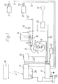
In Figur 1 ist gemäß einem ersten Ausführungsbeispiel ein
fernsteuerbares Schloß mit den wesentlichen Schloßteilen
vereinfacht dargestellt, das zur Verriegelung einer nicht
dargestellten Kraftfahrzeugtür vorgesehen ist. Das Schloß
weist in an sich bekannter Weise eine um die Achse 1 zwischen
einer Offenstellung und der dargestellten Verriegelungsstellung
schwenkbare Drehfalle 2 auf, die bei dem
Ausführungsbeispiel als Gabelfalle ausgebildet ist. In
Offenstellung der Drehfalle 2 kann ein Schließbolzen 3
oder dergleichen in eine von zwei Schenkeln 4, 4' der
Drehfalle 2 begrenzte Ausnehmung eintreten. Ist die Drehfalle
2 im Zusammenwirken mit dem Schließbolzen 3 oder
dergleichen in die dargestellte Verriegelungsstellung
eingeschwenkt, verlagert sich eine um die Achse 6
schwenkbare Sperrklinke 5 unter der Kraft einer nicht
dargestellten Feder selbsttätig vor eine Rastfläche der
Drehfalle 2, so daß diese verriegelt und der Schließbolzen
3 oder dergleichen festgehalten ist. Die nicht dargestellte
Kraftfahrzeugtür weist keinen üblichen Schließzylinder
auf, über den die bekannten Schlösser beispielsweise
mittels eines mechanischen Schlüssels ver- oder
entriegelbar sind. An der Kraftfahrzeugtür ist ein manuell
verstellbarer Türinnengriff 7 und ein manuell verstellbarer
Türaußengriff 8 vorgesehen. Der Türinnengriff
7 ist über einen Leitungsabschnitt 9 und der Türaußengriff
8 über einen Leitungsabschnitt 10 jeweils einer
Elektroleitung mit einer zentralen Karosserieelektronik
11 verbunden. In dem Leitungsabschnitt 9 ist ein Mikroschalter
12 und in dem Leitungsabschnitt 10 ein Mikroschalter
13 angeordnet, die jeweils bei einer Betätigung
des zugeordneten Türinnengriffes 7 bzw. Türaußengriffes 8
einen elektrischen Stellantrieb 14 zur Entriegelung der
Sperrklinke 5 aktivieren, wenn der betreffende Mikroschalter
12 bzw. 13 von der zentralen Karosserieelektronik
11 aktiv gesetzt ist, die jeden Mikroschalter 12, 13
einzeln und gemeinsam aktiv und wirkungslos setzen kann.
Ist bei diesem elektromechanischen Betätigungsmechanismus
beispielsweise der Mikroschalter 12 aktiv gesetzt, so ist
lediglich der Türinnengriff 7 beispielsweise gegen die
Kraft einer Feder anzuheben, damit der Stellantrieb 14
sein Stellglied 15 von der durch den Pfeil 15' gekennzeichneten
Normallage in die durch die Spitze des Pfeiles
15" gekennzeichnete Lage verstellt und dadurch mit dem
Stellglied 15 auf einen Hebelarm 16 der Sperrklinke 5
einwirkt. Dadurch wird die Sperrklinke 5 aus dem öffnungsverstellbereich
der Drehfalle 2 verlagert, so daß
diese unter der Kraft einer Feder in ihre Offenstellung
schwenkt und den Schließbolzen 3 oder dergleichen freigibt.
Die zentrale Karosserieelektronik 11 steht mit einer
ortsfesten Empfangseinrichtung 17 in Verbindung, die
über einen tragbaren Sender 18, der beispielsweise Funksignale
abstrahlen kann, ansteuerbar ist. Die Empfangseinrichtung
17 wertet die ankommenden Funksignale aus und
gibt bei zulässigen Signalen Schaltbefehle an die zentrale
Karosserieelektronik 11 ab, die daraufhin je nach
Schaltbefehl die Mikroschalter einzeln oder gemeinsam aktiv
oder wirkungslos setzt. Bei der vorliegenden Ausführung
kann die Empfangseinrichtung 17 den Stellantrieb 14
auch unter Umgehung der zentralen Karosserieelektronik 11
ansteuern. Aus Sicherheitsgründen ist in der Verbindungsleitung
19 zwischen der zentralen Karosserieelektronik 11
und dem Stellantrieb 14 ein Sicherheitsrelais angeordnet,
das mit einem Sensor 21 in Verbindung steht und beispielsweise
ein Tachosignal empfängt. Das Sicherheitsrelais
20 unterbricht die Verbindungsleitung 19, wenn das
Kraftfahrzeug vorzugsweise nicht steht oder eine geringe
Fahrgeschwindigkeit aufweist, so daß in diesem Fall der
Stellantrieb 14 nicht von der zentralen Karosserieelektronik
11 ansteuerbar ist. An die zentrale Karosserieelektronik
11 ist ein Crash-Sensor 22 angeschlossen, der
bei einer vorgegebenen Fahrzeugverzögerung bewirkt, daß
die zentrale Karosserieelektronik 11 die Mikroschalter
12, 13 aktiv setzt. Die Funktion des Sicherheitsrelais 20
bleibt erhalten. In einer Leitung 23 zwischen der
Empfangseinrichtung 17 und der zentralen Karosserieelektronik
11 ist ein Schalter 24 vorgesehen, der im Fahrgastraum
des Kraftfahrzeugs beispielsweise in der Nähe
des Fahrers angeordnet ist und bei einer entsprechenden
Betätigung bewirken kann, daß die zentrale Karosserieelektronik
die Mikroschalter 12, 13 einzeln oder gemeinsam
aktiviert oder wirkungslos setzt. Durch entsprechende
Ansteuerung der Empfangseinrichtung 17 über den Sender 18
und durch Betätigung des Schalters 24 kann somit lediglich
eine Verriegelung der betreffenden Fahrzeugtür von
außen oder zur Kindersicherung lediglich eine Verriegelung
von innen oder eine Verriegelung des Schlosses von
innen und außen erreicht werden. Um zu vermeiden, daß
nach dem gewaltsamen Eindringen in das Fahrzeug beispielsweise
durch Zerstörung einer Fensterscheibe über
den Schalter 24 die Schlösser einzeln oder gemeinsam
entriegelt werden, ist bei dem Ausführungsbeispiel vorgesehen,
daß nach dem Verlassen des Kraftfahrzeugs der
Schalter 24 zur Diebstahlsicherung über den Sender und
die Empfangseinrichtung wirkungslos gesetzt werden kann.
Zur Spannungsversorgung der elektrischen bzw. elektronischen
Bauteile ist die Fahrzeugbatterie 25 vorgesehen.
Bei dem Ausführungsbeispiel ist auch eine Reservebatterie
26 beispielsweise in Form einer Lithiumbatterie vorgesehen,
die von der Fahrzeugbatterie 25 oder einem Generator
geladen ist. Erforderlichenfalls kann die Lithiumbatterie
26 und/oder die Fahrzeugbatterie 25 von einer externen
Stromquelle aufgeladen werden, die an einen entsprechenden
Fahrzeugstecker von außen anschließbar ist. Beim Anheben
des Türinnengriffes 7 oder des Türaußengriffes 8
erfaßt die Empfangseinrichtung 17 oder die zentrale
Karosserieelektronik 11 einen Spannungsabfall der Fahrzeugbatterie
25 beispielsweise bei einem Störfall, wodurch
die Ersatzbatterie 26 selbsttätig zugeschaltet
wird.According to a first exemplary embodiment, FIG
remote-controlled lock with the essential parts of the lock
shown in simplified form, that for locking one not
Motor vehicle door shown is provided. The castle
has in a manner known per se between the
Die nachfolgenden Ausführungesbeispiele sind ähnlich wie das erste Ausführungsbeispiel gebildet und weisen lediglich zusätzlich einen mechanischen Betätigungsmechanismus auf, über den nach einem Ausfall der elektrischen Verstelleinrichtung durch Betätigung der Handhabe die Sperrklinke mechanisch von der Drehfalle wegverlagerbar ist. Zur Vermeidung einer wiederholten Beschreibung gleicher oder gleichartiger Teile, sind diese mit gleichen Bezugszahlen versehen.The following examples are similar to formed the first embodiment and only have additionally a mechanical actuation mechanism on, after a failure of the electrical adjustment device the pawl by operating the handle is mechanically displaceable from the catch. To avoid a repeated description of the same or similar parts, they have the same reference numbers Mistake.
Das zweite Ausführungsbeispiel gemäß Figur 2 sieht einen
zusätzlichen, mechanischen Betätigungsmechanismus vor,
der einen zwischen einer Wirkstellung und der dargestellten
Sicherungsstellung um eine Achse 27 schwenkbaren
Schwenkhebel 28 aufweist. Dieser ist von einer nicht dargestellten
Feder in die Sicherungsstellung belastet, in
der der Schwenkhebel 28 nicht mit der Sperrklinke 5 zusammenwirken
kann. Durch Zusammenwirken eines Schenkels
28' des Schwenkhebels 28 mit einem Ende 29 des Stellantriebs
14 kann der Schwenkhebel 28 von dem Stellantrieb
14 in die durch eine unterbrochene Umrißlinie dargestellte
Wirkstellung geschwenkt werden, wobei das Stellglied
15 von der durch den Doppelpfeil 15' gekennzeichneten
Normallage in die durch die Spitze des Pfeiles 15'"
angegebene Betätigungslage gelangt. Hierzu ist der Stellantrieb
14 von der Empfangseinrichtung 17 bzw. von der
zentralen Karosserieelektronik und ggf. von dem aktiv gesetzten
Schalter 24 entsprechend anzusteuern. Die eine
Schwenkachse für den Schwenkhebel 28 bildende Achse 27
ist an einem Tragteil 30 ausgebildet, das durch Betätigung
des Türinnengriffes 7 oder des Türaußengriffes 8 jeweils
von der dargestellten Ruhelage beispielsweise über
einen symbolisch dargestellten Seilzug 31 gegen die Kraft
einer Feder 33 in Pfeilrichtung 32 in eine Betätigungslage
geradlinig verstellbar ist. In dem Schwenkhebel 28
ist eine Durchtrittsöffnung 36 ausgebildet, in die in
Wirkstellung des Schwenkhebels 28 ein zweiter Schenkel 34
der Sperrklinke 5 eingreift oder die von dem Schenkel 34
durchsetzt ist. Befindet sich der Schwenkhebel 28 in
seiner durch eine unterbrochene Umrißlinie dargestellten
Wirkstellung, so bewirkt die mechanische Verlagerung des
Tragteiles 30 in Pfeilrichtung 32 eine Mitnahme des zweiten
Schenkels 34 an der Sperrklinke 5, wodurch diese in
Pfeilrichtung 35 um die Achse 6 in ihre die Drehfalle 2
freigebende Entriegelungsstellung schwenkt. Die Durchtrittsöffnung
36 weist eine solche Länge auf, daß sich in
Wirkstellung des Schwenkhebels 28 der Schenkel 34 und damit
die Sperrklinke 5 ohne Verlagerung des Schwenkhebels
28 von dem Stellantrieb 14 im Zusammenwirken mit dem Hebelarm
16 elektromechanisch in die Entriegelungsstellung
verlagern läßt. Der Schwenkhebel 28 kann durch einen entsprechenden
Befehl des Senders 18 an die Empfangseinrichtung
17 und über den wirksam gesetzten Schalter 24 durch
Aktivierung des Stellantriebs 14 in die Wirkstellung verlagert
werden, die durch die unterbrochene Umrißlinie angegeben
ist. Wird das Stellglied 15 aus der durch den
Pfeil 15'" angegebenen Betätigungslage in die durch den
Doppelpfeil 15' gekennzeichnete Normallage zurückgestellt,
so schwenkt der Schwenkhebel 28 unter der Kraft
der nicht dargestellten Feder in die dargestellte Sicherungsstellung.
Spricht der Crash-Sensor 22 bei einer
übermäßigen Fahrzeugverzögerung an, so bewirkt die zentrale
Karosserieelektronik 11 durch entsprechende Ansteuerung
des Stellantriebs 14, daß der Schwenkhebel 28
in seine Wirkstellung schwenkt, in der der Türinnengriff
7 bzw. der Türaußengriff 8 über den Seilzug 31 oder eine
andere Übertragungseinrichtung und den Schwenkhebel 28
die Sperrklinke 5 mechanisch in ihre Entriegelungsstellung
verlagert. Im Normalfall ist bei einzeln oder gemeinsam
aktiv gesetzten Mikroschaltern 12, 13 ein elektromechanisches
Entriegeln der Sperrklinke 5 vorgesehen.
Die zusätzliche mechanische Entriegelung wird lediglich
bei auftretenden Störfällen verwendet und wird in diesen
Fällen von der Empfangseinrichtung, von der zentralen Karosserieelektronik
oder von dem aktiv gestellten Schalter
24 wirksam gesetzt. Ist beispielsweise bei einem Ausfall
der Fahrzeugbatterie 25 die Reservebatterie 26 zugeschaltet,
so ist lediglich eine geringe Energie erforderlich,
um den lediglich von einer Feder in die Sicherungsstellung
belasteten Schwenkhebel 28 gegen die Kraft dieser
Feder in die Wirkstellung zu verschwenken.The second exemplary embodiment according to FIG. 2 sees one
additional mechanical actuation mechanism
the one between an active position and the one shown
Secured position pivotable about an
In Figur 3 ist gemäß einem dritten Ausführungsbeispiel
ein fernsteuerbares Schloß dargestellt, das an einer
Kraftfahrzeugtür vorgesehen ist. Bei aktiv gestellten
Mikroschaltern 12, 13 erfolgt die Entriegelung der Sperrklinke
5 in der nach dem Ausführungsbeispiel gemäß Figur
1 angegebenen Weise. Um beispielsweise bei einem Stromausfall,
nach dem die Mikroschalter 12, 13 nicht aktivierbar
sind, dennoch die Sperrklinke betätigen zu können,
ist eine mechanische Betätigungseinrichtung vorgesehen,
über die der Stellantrieb 114 durch Betätigung entweder
des Türinnengriffes 7 oder des Türaußengriffes 8
axial verstellbar ist. In der dargestellten Normallage
des Stellantriebs 114 liegt dieser unter der Kraft einer
Feder 127 an einem Anschlag 128 an. An der zur Sperrklinke
5 abgewandten Stirnseite des Stellantriebs 114 ist
eine Seilrolle 129 um die Achse 130 an dem Stellantrieb
114 abgestützt. An der Seilrolle 129 stützt sich an dem
oberen Umfangsbereich ein lediglich symbolisch dargestelltes
Seil 131 ab, das an einem Ende 132 beispielsweise
an einer Schloßplatte abgestützt ist und mit dem
anderen Ende unter Zwischenschaltung von Umlenkrollen
133, 133', 133", 133'" mit dem Türinnengriff 7 und dem
Türaußengriff 8 verbunden ist. Durch Betätigung des Türinnengriffes
7 oder des Türaußengriffes 8 über einen gegenüber
dem elektrischen Entriegeln größeren Verstellbereich
wird das betreffende Seil 131 gespannt und durch
eine axiale Kraftkomponente des Seiles 131 in Pfeilrichtung
134 der Stellantrieb 114 entgegen der Kraft der Feder
127 axial verstellt. Befindet sich das Stellglied 115
in seiner dargestellten, durch die Spitze des Pfeiles
115' angegebenen Wirkstellung, so kann der Stellantrieb
114 bei seiner axialen Verstellbewegung über das Stellglied
115 die Sperrklinke 5 aus dem öffnungsverstellbereich
der Drehfalle 2 verlagern. Ist dagegen das Stellglied
115 bis zur Spitze des Pfeiles 115'" in den Stellantrieb
114 eingefahren, so kann der Stellantrieb 114 bei
dieser axialen Verstellbewegung nicht über das Stellglied
115 mit der Sperrklinke 5 zusammenwirken, die somit in
ihrer dargestellten Verriegelungsstellung verbleibt. Auf
diese Weise kann die Sperrklinke bei funktionierenden
elektrischen Bauteilen, beispielsweise durch eine kleine
Schwenkbewegung des Türinnengriffes 7 oder Türaußengriffes
8 den zugeordneten Microschalter 12 oder 13 betätigen,
um ein im wesentlichen elektrisches Verlagern des
Stellgliedes 115 in die durch den Pfeil 115" dargestellte
Betätigungslage zu bewirken, wodurch sich die Sperrklinke
5 von der Drehfalle 2 wegverlagert. Bei diesem elektrischen
Verriegeln verbleibt der Stellantrieb 114 in seiner
dargestellten Lage. Je nach konstruktiver Ausführung kann
der Stellantrieb 114 auch eine kleine Verstellbewegung in
Richtung des Pfeiles 134 ausführen, die jedoch kein
mechanisches Entriegeln der Sperrklinke bewirkt. Bei
einem Ausfall elektrischer oder elektronischer Bauteile
ist lediglich dafür zu sorgen, daß sich das lastfreie
Stellglied 115 in die durch das Ende des Pfeiles 115' gekennzeichnete
Wirkstelltung verlagert und beispielsweise
durch Selbsthemmung arretiert ist. In diesem Fall bewirkt
eine Schwenkbewegung des Türinnengriffes 7 bzw. des Türaußengriffes
8 beispielsweise über einen gegenüber dem
elektrischen Entriegeln größeren Verstellbereich, daß
sich der Stellantrieb 114 in Pfeilrichtung 134 verstellt
und dabei das Stellglied 115 die Sperrklinke im Entriegelungssinn
betätigt.In Figure 3 is according to a third embodiment
a remote-controlled lock shown on a
Motor vehicle door is provided. When actively set
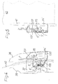
Das vierte Ausführungsbeispiel gemäß Figur 4 ist ähnlich
wie das dritte Ausführungsbeispiel gebildet. Um eine
wiederholte Beschreibung von Bauteilen zu vermeiden, sind
die zwischen den beiden Ausführungsbeispielen 3 und 4
vergleichbaren Bauteile mit gleichen Bezugszahlen oder
gleichen Bezugszahlen und einem hochgestellten Zeichen
versehen. Bei dieser Ausführung ist der Stellantrieb 114'
um die Achse 1' der Drehfalle 2' schwenkbar angeordnet
und von der Feder 135 gegen den Anschlag 136 in die dargestellte
Normallage belastet. Das Stellglied 115 ist in
den Stellantrieb 114' eingefahren, so daß der Stellantrieb
114' durch Betätigung des Türinnengriffes oder des
Türaußengriffes zwar um die Achse 1' verschwenken, dabei
jedoch nicht das Stellglied 115 mit der Sperrklinke 5'
zusammenwirken kann. Ist dagegen das Stellglied 115 in
seine durch eine unterbrochene Umrißlinie dargestellte
Wirkstellung ausgefahren, so kann das Stellglied 115 beim
Verschwenken des Stellantriebs 114' in eine der Spitze
des Pfeiles 15" in Figur 3 entsprechende Wirkbereitschaftsstellung
mit der Sperrklinke 5' zusammenwirken, um
diese aus dem öffnungsverstellverbereich der Drehfalle 2'
zu verlagern. In der Figur sind das die Schloßteile tragende
Schloßblech 37, das Außen- und Innenblech 38, 39
der Fahrzeugtür und eine an der Fahrzeugtür höhenverstellbare
Seitenscheibe 40 erkennbar. The fourth exemplary embodiment according to FIG. 4 is similar
formed like the third embodiment. To one
repeated description of components should be avoided
between the two
Aus der Seitenansicht gemäß Figur 5 sind weitere konstruktive
Einzelheiten des Ausführungsbeispiels gemäß
Figur 4 entnehmbar, wobei beispielsweise zu erkennen ist,
daß der Türaußengriff und der Türinnengriff jeweils über
ein separates Seil 131, 131' unabhängig voneinander mit
dem Stellantrieb 114' zusammenwirken. In dieser Ansicht
ist auch eine Führungsschiene 41 der Seitenscheibe 40 erkennbar.From the side view according to Figure 5 are more constructive
Details of the embodiment according to
FIG. 4 can be seen, for example,
that the outer door handle and the inner door handle each over
a
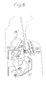
Das in Figur 6 dargestellte fünfte Ausführungsbeispiel
ist ähnlich wie das vierte Ausführungsbeispiel gemäß
Figur 4 gebildet. Die zwischen den beiden Ausführungsbeispielen
gemäß den Figuren 4 und 6 vergleichbaren Bauteile
sind mit gleichen Bezugszahlen oder gleichen Bezugszahlen
und einem gleichen oder geänderten hochstehenden Zeichen
versehen, um eine wiederholte Beschreibung gleichartiger
Bauteile zu vermeiden. Bei der Figur 6 entsprechenden
Ausführung ist der Stellenantrieb 114" um die Achse 6"
der Sperrklinke 5" schwenkbar angeordnet. Das Stellglied
115 ist in seine Wirkstellung ausgefahren. Beispielsweise
nach einem Ausfall der elektrischen Einrichtung des
Schlosses kann in dieser Lage des Stellglieds 115 durch
Betätigung des Türinnengriffes bzw. des Türaußengriffes
über das zugeordnete Seil 131 bzw. 131' der Stellantrieb
114" verschwenkt und im Zusammenwirken des Stellglieds
115 mit der Sperrklinke 5" diese aus dem Öffnungsverstellbereich
der Drehfalle 2" verlagert werden.The fifth embodiment shown in Figure 6
is similar to the fourth embodiment according to FIG
Figure 4 formed. The between the two embodiments
comparable components according to FIGS. 4 and 6
have the same reference numbers or the same reference numbers
and an identical or changed high character
provided a repeated description of the same type
Avoid components. Corresponding to FIG. 6
Execution is the actuator 114 "around the
Die Erfindung wurde anhand von fünf Ausführungsbeispielen erläutert, auf die der Erfindungsgegenstand nicht eingeschränkt ist. Es sind auch zahlreiche andere Ausführungen möglich, ohne den Erfindungsgedanken aufzugeben. Der Schalter kann beispielsweise in mehrere Einzelschalter aufgeteilt sein, von denen jeweils ein Schalter oder einige einer Fahrzeugtür zugeordnet und beispielsweise an dieser Fahrzeugtür angeordnet sein können. Ein mit dem Tragteil vergleichbares Teil kann auch schwenkbar oder auf andere Weise verstellbar angeordnet sein. Der Seilzug kann durch andere Übertragungselemente ersetzt sein. Ein Verstellen des Schwenkhebels kann unabhängig von dem Stellantrieb über einen separaten Antrieb bewirkt werden. Der Schwenkhebel kann durch ein anderes, beispielsweise geradlinig an dem Tragteil verstellbares Übertragungselement gebildet sein. Es können auch weitere Schalter vorgesehen sein, die Positionen verstellbarer Bauteile, beispielsweise der Drehfalle, der Sperrklinke, des Tragteiles oder des Schwenkhebels erfassen. Der Stellantrieb und ggf. der Antrieb kann auch beispielsweise hydraulisch, pneumatisch oder elektromagnetisch betrieben sein. Der Sender kann beliebige Signale beispielsweise im Radiowellenbereich senden. Es sind aber auch fernwirksame Wellen wie Lichtstrahlen, Infrarotstrahlen, Ultraschall usw. zur Signalübertragung verwendbar. Bei Verwendung des verstellbaren Stellantriebs ist die Bewegungsbahn des Stellantriebs beliebig vorgebbar. Die mechanische Verstellbewegung des verstellbaren Stellantriebs kann auch auf andere Weise, beispielsweise ohne zwischengeschaltete Seile, unter Verwendung von übertragungselementen und/oder -stangen erfolgen. Es ist auch möglich, daß anstelle oder zusätzlich zu dem mechanischen Betätigungsmechanismus ein elektrischer oder elektronischer Betätigungsmechanismus vorgesehen ist, der im Störfall bei nicht aktiv stellbaren Schaltern bzw. Mikroschaltern in der Nähe der Handhabe bzw. der Handhaben, eventuell unter Verwendung einer Hilfsbatterie oder einer von außen einzuspeisenden Fremdenergie eine Notentriegelung der Sperrklinke ermöglicht.The invention was based on five exemplary embodiments to which the subject of the invention is not limited is. There are also numerous other versions possible without giving up the idea of the invention. Of the Switch can, for example, in several individual switches be divided, each of which is a switch or some assigned to a vehicle door and for example on this vehicle door can be arranged. One with the Carrier part comparable part can also be swiveled or be arranged adjustable in another way. The cable pull can be replaced by other transmission elements. A Adjusting the swivel lever can be done independently Actuator can be effected via a separate drive. The pivot lever can by another, for example Transmission element adjustable in a straight line on the supporting part be educated. Additional switches can also be provided be the positions of adjustable components, for example the catch, the pawl, the supporting part or the swivel lever. The actuator and if necessary, the drive can also be hydraulic, for example, be operated pneumatically or electromagnetically. Of the Transmitter can transmit any signals, for example in the radio wave range send. But there are also waves that affect the distance such as light rays, infrared rays, ultrasound, etc. for Signal transmission can be used. When using the adjustable Actuator is the movement path of the actuator freely definable. The mechanical adjustment movement the adjustable actuator can also on other way, for example without an intermediary Ropes using transmission elements and / or rods. It is also possible that instead or in addition to the mechanical actuation mechanism an electrical or electronic actuation mechanism is provided in the event of a malfunction switches or microswitches in close to the handle or handles, possibly under Use of an auxiliary battery or an external one External energy an emergency release of the pawl enables.
Claims (21)
- A remotely controllable lock, especially for motor vehicle doors, with a portable transmitter and a fixed receiving arrangement, which converts signals radiated from the transmitter into switching commands for parts of the lock, with a rotary latch interacting with a catch bolt or similar, which is held in the locking position by a latch lever, which can be moved into a position which releases the rotary latch by operation of a handle of an operating mechanism, when the operating mechanism, which can be set to active or inoperative by switching commands from the receiving arrangement, has been set to active, characterised in that the handle (7, 8) is connected by an electric cable (9, 10) with a motorised positioning drive (14, 114, 114', 114"), which on operation of the handle (7, 8) interacts with a movable positioning component (15, 115) on the latch lever (5), moving it into its unlatched position, when one of the switches (12, 13) arranged in the electrical cable (9, 10) has been set to active by a suitable switching command from the receiving arrangement (17) or a device in standing connection with it (11, 24).
- A remotely controllable lock in accordance with Claim 1, characterised in that the operating mechanism has a transmission element (28) movable between a working position and a secure position, which in the working position is displaced by operation of the handle (7, 8) in a further operational direction (32) and thereby effects a mechanical movement of the latch lever (5) into its unlatching position.
- A remotely controllable lock in accordance with Claim 2, characterised in that the transmission element is a rocking lever (28) which can be moved somewhat linearly in the further direction of movement (32), interacting with a shoulder (34) of the latch lever (5), with a through opening (36) for the shoulder (34) of the latch lever (5) and the through opening (36) has such a length that in the working position of the transmission element (28) the latch lever (5) can be displaced into its unlatching position without displacement of the transmission element (28) by the motorised positioning drive (14).
- A remotely controllable lock in accordance with Claim 2 or Claim 3, characterised in that the transmission element (28) is loaded by a spring in the secure position, in which the transmission element (28) cannot interact with the latch lever (5).
- A remotely controllable lock in accordance with any one of the Claims 2 to 4, with a lock arranged on a vehicle door of a motor vehicle, characterised in that the handle comprises an inner door handle (7) and an outer door handle (8), which, in the working setting of the transmission element (28), independently of each other, operate in each case a mechanical adjustment of the transmission element (28) in a further operational direction (32) and thereby effect a mechanical movement of the latch lever (5) into its unlatching position.
- A remotely controllable lock in accordance with Claim 5, characterised in that the inner door handle (7) and the outer door handle (8) each are connected over their own cable section (9, 10) of the electric cable to the positioning drive (14) and in each cable section (9, 10) a switch (12, 13) is arranged, which can be set by switching commands from the receiving arrangement (17) to be active or inoperative.
- A remotely controllable lock in accordance with any one of the Claims 2 to 6, characterised in that the transmission element (28) can be set by a drive (14) into the working position.
- A remotely controllable lock in accordance with Claim 7, characterised in that the drive is the motorised positioning drive (14).
- A remotely controllable lock in accordance with Claim 7 or Claim 8, characterised in that in the passenger space of the motor vehicle a switching element (24) is arranged, connected to the drive (14), which, in accordance with the switch setting, by means of the drive (14), and possibly a spring, effects a movement of the transmission element (28) into its working position or into its secure position.
- A remotely controllable lock in accordance with Claim 9, characterised in that the switching element (24) can be set to be operational or ineffective by a corresponding switching command from the receiving arrangement (17).
- A remotely controllable lock in accordance with any one of the Claims 5 to 10, characterised in that a crash sensor (22) is connected to the receiving arrangement or to a signal processing device (central vehicle body electronics 11), which at a given vehicle deceleration causes a displacement of the transmission element (28) into its working position and/or sets the switch or switches (12, 13) in the electric cable (10, 9) to active.
- A remotely controllable lock in accordance with any one of the Claims 5 to 11, characterised in that the switch (12, 13) in the electric cable (9, 10) can only be set to active when the vehicle is stationary or travelling slowly, by the application of a safety relay (20) in the connecting cable (19) between the positioning drive (14) and the central vehicle body electronics (11) or the receiving arrangement.
- A remotely controllable lock in accordance with any one of the Claims 1 to 12, characterised in that the positioning drive (14) and/or the drive is driven hydraulically, pneumatically, electrically, electromagnetically or similarly.
- A remotely controllable lock in accordance with Claim 1, characterised in that operation of the handle (7, 8) at least over a greater range of movement moves the positioning drive (114, 114', 114") out of its normal position into an operationally ready position and the positioning component (115) of the positioning drive (114, 114', 114") moves the latch lever (5, 5', 5") into its unlatching position, when the positioning component (115) is moved by the receiving arrangement or an emergency energy supply into a working position, in which the positioning component (115) can interact with the latch lever (5, 5', 5").
- A remotely controllable lock in accordance with Claim 14, characterised in that the positioning drive (114) can be moved linearly.
- A remotely controllable lock in accordance with Claim 14, characterised in that the positioning drive (114', 114") is arranged to be able to swivel.
- A remotely controllable lock in accordance with Claim 16, characterised in that the positioning drive (114") can be swivelled about the pivot (6") of the latch lever (5").
- A remotely controllable lock in accordance with Claim 16, characterised in that the positioning drive can be swivelled about the pivot (1") of the rotary latch (2').
- A remotely controllable lock in accordance with any one of the Claims 14 to 18, characterised in that the positioning drive (114, 114', 114") is biassed by a spring (127, 135) in the normal position, and limited by a stop (128, 136, 136')
- A remotely controllable lock in accordance with any one of the Claims 14 to 19, characterised in that the operational readiness position of the positioning drive (114, 114', 114") is limited by a stop component.
- A remotely controllable lock in accordance with one of the Claims 14 to 20,, characterised in that the positioning drive (114, 114', 114") can be moved by a control cable (cable 131, 131') from the handle (7, 8).
Applications Claiming Priority (4)
| Application Number | Priority Date | Filing Date | Title |
|---|---|---|---|
| DE4228233 | 1992-08-25 | ||
| DE4228233A DE4228233A1 (en) | 1992-08-25 | 1992-08-25 | Remotely controlled lock for vehicle central door-locking system - receives remote control-signal to operate microswitch in current circuit for locking latch setting drive |
| DE4240013 | 1992-11-27 | ||
| DE4240013A DE4240013A1 (en) | 1992-08-25 | 1992-11-27 | Remote controllable lock, in particular for motor vehicle doors |
Publications (2)
| Publication Number | Publication Date |
|---|---|
| EP0589158A1 EP0589158A1 (en) | 1994-03-30 |
| EP0589158B1 true EP0589158B1 (en) | 1998-01-28 |
Family
ID=25917866
Family Applications (1)
| Application Number | Title | Priority Date | Filing Date |
|---|---|---|---|
| EP93110812A Expired - Lifetime EP0589158B1 (en) | 1992-08-25 | 1993-07-07 | Remote controlled lock, particularly for motor vehicle doors |
Country Status (2)
| Country | Link |
|---|---|
| EP (1) | EP0589158B1 (en) |
| DE (2) | DE4240013A1 (en) |
Cited By (5)
| Publication number | Priority date | Publication date | Assignee | Title |
|---|---|---|---|---|
| DE102007035218A1 (en) | 2007-07-25 | 2009-01-29 | Keba Ag | Electrically automated unlocking lock, especially for locker-like storage systems |
| DE202008003845U1 (en) | 2008-03-19 | 2009-08-13 | Kiekert Ag | Door lock unit for a motor vehicle |
| EP2336465A2 (en) | 2009-12-18 | 2011-06-22 | Brose Schliesssysteme GmbH & Co. KG | Circuit and method for preventing a vehicle door from opening unintentionally |
| DE102009059084A1 (en) | 2009-12-18 | 2011-06-22 | Brose Schließsysteme GmbH & Co. KG, 42369 | Circuit arrangement for motor vehicle door, has locking mechanism that holds motor vehicle door in closed position or open position, where actuator is particularly equipped at outside door handle or inside door handle |
| DE202014102567U1 (en) | 2014-06-02 | 2015-09-03 | BROSE SCHLIEßSYSTEME GMBH & CO. KG | Motor vehicle lock |
Families Citing this family (75)
| Publication number | Priority date | Publication date | Assignee | Title |
|---|---|---|---|---|
| IT1268616B1 (en) * | 1994-10-04 | 1997-03-06 | Roltra Morse Spa | ELECTRICALLY OPERATED LOCK FOR A VEHICLE DOOR. |
| DE19500284A1 (en) * | 1995-01-06 | 1996-07-18 | Bocklenberg & Motte Bomoro | Motor vehicle door lock device for a double tailgate |
| DE19501493B4 (en) * | 1995-01-19 | 2006-06-22 | Kiekert Ag | Motor vehicle door lock |
| US6050117A (en) * | 1995-10-13 | 2000-04-18 | Robert Bosch Gmbh | Motor vehicle door lock or the like |
| DE19545722A1 (en) * | 1995-10-13 | 1997-04-17 | Bosch Gmbh Robert | Motor vehicle door lock or the like. |
| DE19619849C2 (en) * | 1995-12-20 | 2001-03-15 | Mannesmann Vdo Ag | Lock, in particular for motor vehicle doors |
| DE19600524B4 (en) | 1995-12-20 | 2006-07-06 | Siemens Ag | Lock, in particular for motor vehicle doors |
| US6279361B1 (en) | 1995-12-20 | 2001-08-28 | Vdo Adolf Schindling Ag | Lock in particular for motor vehicle doors |
| DE19547727A1 (en) * | 1995-12-20 | 1997-06-26 | Vdo Schindling | Servo-driven door lock for vehicle |
| EP0808977B1 (en) * | 1996-05-21 | 2000-08-16 | Robert Bosch Gmbh | Method for controlling an electrically actuated vehicle door lock |
| FR2749873B1 (en) * | 1996-06-18 | 1999-03-26 | Peugeot | SYSTEM FOR OPENING A MOTOR VEHICLE DOOR |
| FR2752004B1 (en) | 1996-07-30 | 1998-09-25 | Siemens Automotive Sa | DEVICE FOR CONTROLLING ACCESS TO A SPACE CLOSED BY A DOOR |
| DE19635414C2 (en) * | 1996-08-31 | 2001-07-12 | Mannesmann Vdo Ag | Lock, especially for vehicle doors or the like |
| DE19636464A1 (en) * | 1996-09-07 | 1998-03-12 | Mannesmann Vdo Ag | Locking device, in particular for vehicle doors or the like |
| GB2322409B (en) * | 1996-12-16 | 2001-05-23 | John Phillip Chevalier | Control system for opening a door |
| BR9807162A (en) | 1997-02-04 | 2000-03-14 | Atoma Int Corp | Mechanically operated vehicle door locking device and system |
| DE19706657C5 (en) | 1997-02-20 | 2007-06-28 | Siemens Ag | Lock for a door of a vehicle |
| DE19710531B4 (en) * | 1997-03-14 | 2007-01-18 | Brose Schließsysteme GmbH & Co.KG | Motor vehicle door lock |
| FR2765611B1 (en) * | 1997-07-04 | 1999-08-20 | Valeo Systemes De Fermetures | DEVICE FOR OPENING A VEHICLE LOCK |
| US6102454A (en) * | 1997-09-15 | 2000-08-15 | Robert Bosch Gmbh | Motor vehicle door lock arrangement |
| DE19754216C2 (en) * | 1997-09-15 | 2000-09-14 | Bosch Gmbh Robert | Motor vehicle door locking device |
| FR2769037B1 (en) * | 1997-10-01 | 1999-11-19 | Valeo Securite Habitacle | LOCKING DEVICE COMPRISING A CAM-CONTROLLED TRANSMISSION FINGER |
| US6072403A (en) * | 1997-12-05 | 2000-06-06 | Kabushiki Kaisha Tokai Rika Denki Seisakusho | Door unlocking device for vehicle |
| EP0922826A3 (en) * | 1997-12-10 | 2002-01-16 | Delphi Automotive Systems Deutschland GmbH | Method and device for controlling the lock status of a vehicle door |
| JP2001509849A (en) * | 1997-12-12 | 2001-07-24 | フィリップ シュヴァリエ ジョン | Latch device for motor vehicle doors or other closures |
| DE19755843A1 (en) * | 1997-12-15 | 1999-06-24 | Bosch Gmbh Robert | Actuator for an electric lock on a motor vehicle door |
| GB9802955D0 (en) * | 1998-02-11 | 1998-04-08 | Rover Group | A motor vehicle door locking system |
| FR2778197B1 (en) * | 1998-04-30 | 2000-06-23 | Valeo Securite Habitacle | MOTOR VEHICLE DOOR LOCK WITH EMERGENCY CONVICTION |
| FR2778198A1 (en) * | 1998-04-30 | 1999-11-05 | Valeo Securite Habitacle | Automobile central door locking system with rear childproof door lock |
| FR2778940B1 (en) * | 1998-05-19 | 2000-07-28 | Valeo Securite Habitacle | MOTOR VEHICLE DOOR LOCK WITH ELECTRIC LOCKING AND ELECTRIC OPENING |
| US6343494B2 (en) * | 1998-08-11 | 2002-02-05 | Mannesmann Vdo Ag | Locking device |
| FR2783550B1 (en) * | 1998-09-21 | 2000-12-29 | Valeo Securite Habitacle | LOCK WITH AUTOMATIC LOCKING ON OPENING |
| FR2783549B1 (en) * | 1998-09-21 | 2000-12-29 | Valeo Securite Habitacle | SIMPLIFIED LOCK FOR MOTOR VEHICLE DOOR |
| DE19902797C1 (en) | 1999-01-25 | 2000-06-21 | Kostal Leopold Gmbh & Co Kg | Keyless vehicle access control unit and security system, exchanges low frequency coded signal and response of high frequency transponder before entry is enabled |
| US6099048A (en) * | 1999-03-04 | 2000-08-08 | Ford Global Technologies, Inc. | Automotive door latching system |
| DE19919765A1 (en) | 1999-04-29 | 2000-11-09 | Bosch Gmbh Robert | Motor vehicle door lock or the like. with electrical opening aid and closing aid |
| EP1083285A1 (en) | 1999-09-07 | 2001-03-14 | Robert Bosch Gmbh | Vehicle door locking system |
| DE19942485A1 (en) * | 1999-09-07 | 2001-04-05 | Bosch Gmbh Robert | Motor vehicle door locking system with passive entry function and quick release |
| US6880866B2 (en) | 2000-02-25 | 2005-04-19 | Intier Automotive Closures Inc. | Vehicle door latch |
| EP1257722B1 (en) * | 2000-02-25 | 2004-11-17 | Intier Automotive Closures Inc. | Vehicle door latch |
| DE10015887C1 (en) | 2000-03-30 | 2002-01-17 | Huf Huelsbeck & Fuerst Gmbh | Access system for a vehicle |
| GB0011991D0 (en) | 2000-05-19 | 2000-07-05 | Meritor Light Vehicle Sys Ltd | Latch assembly and vehicle including such a latch assembly |
| GB0031062D0 (en) * | 2000-12-20 | 2001-01-31 | Meritor Light Vehicle Sys Ltd | Latch arrangement |
| DE10100010B4 (en) * | 2001-01-02 | 2005-05-12 | Brose Schließsysteme GmbH & Co.KG | Motor vehicle door lock, designed as an electric lock, and method for assembling a motor vehicle door lock designed as an electric lock |
| DE10164829B4 (en) * | 2001-01-02 | 2006-07-13 | Brose Schließsysteme GmbH & Co.KG | Motor vehicle door lock, designed as an electric lock |
| DE10100008B4 (en) * | 2001-01-02 | 2004-12-16 | Brose Schließsysteme GmbH & Co.KG | Sealed electrically operated lock assembly for motor vehicles, uses sealed box to house lock with external cam driven by shaft that passes through seal fitted to hole in cover of box |
| DE10109825B4 (en) * | 2001-03-01 | 2005-08-11 | Daimlerchrysler Ag | Door lock for a vehicle door |
| ITTO20010757A1 (en) * | 2001-07-31 | 2003-01-31 | Oclap Srl | DEVICE FOR OPENING AND CLOSING A ROTATING-TRANSLATING DOOR FOR MOTOR VEHICLES. |
| GB0121066D0 (en) | 2001-08-31 | 2001-10-24 | Meritor Light Vehicle Sys Ltd | Door latch arrangement |
| FR2832448B1 (en) * | 2001-11-20 | 2005-02-25 | Renault | LOCK, IN PARTICULAR FOR A VEHICLE FOR A MOTOR VEHICLE, AND ASSEMBLY COMPRISING SUCH A LOCK |
| GB0130422D0 (en) * | 2001-12-20 | 2002-02-06 | Meritor Light Vehicle Sys Ltd | Vehicle |
| GB0200691D0 (en) * | 2002-01-14 | 2002-02-27 | Mila Hardware Ltd | Locking mechanism |
| FR2835867B1 (en) | 2002-02-12 | 2004-08-20 | Meritor Light Vehicle Sys Ltd | MOTOR VEHICLE LOCK |
| JP2003269028A (en) * | 2002-03-18 | 2003-09-25 | Aisin Seiki Co Ltd | Door lock releasing device |
| DE10306610C5 (en) | 2003-02-14 | 2008-12-11 | BROSE SCHLIEßSYSTEME GMBH & CO. KG | Motor vehicle door and door lock unit and motor vehicle locking system |
| DE10309644A1 (en) * | 2003-03-06 | 2004-09-16 | Huf Hülsbeck & Fürst Gmbh & Co. Kg | Device for motorized actuation and emergency device for manual actuation of a lock for flaps or doors of vehicles, in particular a glove box lock |
| DE10319743B4 (en) * | 2003-03-08 | 2006-01-12 | Brose Schließsysteme GmbH & Co.KG | A multi function motor vehicle door lock has an electronically controlled motor driven worm drive operating a blocking lever against the locking plate |
| DE10312304B4 (en) | 2003-03-20 | 2005-12-29 | Brose Schließsysteme GmbH & Co.KG | Kraftffahrzeugschloß |
| DE10336050A1 (en) * | 2003-08-01 | 2005-02-24 | Kiekert Ag | Motor vehicle door lock |
| JP4239785B2 (en) * | 2003-10-21 | 2009-03-18 | 三菱自動車工業株式会社 | Vehicle door member opener device |
| DE10360422A1 (en) * | 2003-12-19 | 2005-07-21 | Brose Schließsysteme GmbH & Co.KG | motor vehicle |
| DE10361168B4 (en) * | 2003-12-22 | 2016-08-04 | BROSE SCHLIEßSYSTEME GMBH & CO. KG | Motor vehicle lock, in particular for hoods or flaps |
| DE102004029848A1 (en) * | 2004-06-19 | 2006-01-05 | Blaut Management + Marketing Gmbh | Front hood lock for motor vehicle has lock latch that is actuatable by magnet such that shutter release as well as detent and rotary link are actuated |
| EP1637674B1 (en) * | 2004-09-15 | 2007-06-20 | Huf Hülsbeck & Fürst GmbH & Co. KG | Closure for tailgates or doors of vehicles |
| DE102004045283A1 (en) * | 2004-09-16 | 2006-03-23 | Brose Schließsysteme GmbH & Co.KG | Motor vehicle lock |
| DE202005004390U1 (en) | 2005-03-16 | 2006-07-27 | Brose Schließsysteme GmbH & Co.KG | Motor vehicle lock and holding device for a vehicle safety device |
| FR2942491B1 (en) * | 2009-02-25 | 2016-11-18 | Peugeot Citroen Automobiles Sa | HYBRID DOOR ARCHITECTURE. |
| DE102010046735A1 (en) * | 2010-09-28 | 2012-03-29 | Liebherr-Aerospace Lindenberg Gmbh | Locking system and circuit device for a locking system |
| USD665244S1 (en) | 2011-09-13 | 2012-08-14 | The Eastern Company | Rotary latch |
| CN104453451B (en) * | 2014-11-20 | 2017-05-17 | 广州市暨嘉信息科技有限公司 | Electric control lock |
| DE102015205343A1 (en) * | 2015-03-24 | 2016-09-29 | Kiekert Ag | Electric actuator with emergency power supply for a motor vehicle electric lock and method |
| DE102016113695A1 (en) * | 2016-07-25 | 2018-01-25 | Witte Automotive Gmbh | The door handle assembly |
| DE102019103558A1 (en) | 2018-02-15 | 2019-08-22 | Magna Closures Inc. | A lock-latch assembly for a common kinematic chain motor vehicle for a power release mechanism and a mechanical lock release mechanism |
| DE102018104421A1 (en) * | 2018-02-27 | 2019-08-29 | Kiekert Ag | Actuating device for a motor vehicle door lock |
| DE102019121300A1 (en) * | 2019-08-07 | 2021-02-11 | Daimler Ag | Motor vehicle lock, in particular motor vehicle door lock |
Family Cites Families (9)
| Publication number | Priority date | Publication date | Assignee | Title |
|---|---|---|---|---|
| JPS56100983A (en) * | 1980-01-16 | 1981-08-13 | Nissan Motor | Door lock device for automobile |
| GB2116621B (en) * | 1982-03-04 | 1985-09-18 | Ford Motor Co | Door latch |
| DE3207880A1 (en) * | 1982-03-05 | 1983-09-15 | Ymos-Metallwerke Wolf & Becker Gmbh & Co, 6053 Obertshausen | Door lock for motor vehicles |
| FR2548719B2 (en) * | 1982-07-19 | 1986-06-06 | Cousin Cie Ets A & M Freres | ELECTRIC SECURITY LOCK, ESPECIALLY FOR MOTOR VEHICLE DOORS |
| DE3242527C3 (en) * | 1982-11-18 | 1995-09-07 | Neiman Sa | Lock for a motor vehicle door |
| DE3333746A1 (en) * | 1983-09-19 | 1985-06-05 | Neiman GmbH, 5657 Haan | Lock for a motor-vehicle door |
| DE3334049C2 (en) * | 1983-09-21 | 1990-01-25 | Hülsbeck & Fürst GmbH & Co KG, 5620 Velbert | Electric central locking device for multiple locks in a vehicle |
| DE3536377A1 (en) * | 1985-10-11 | 1987-04-16 | Bayerische Motoren Werke Ag | SAFETY DEVICE FOR MOTOR VEHICLES |
| JPH0747904B2 (en) * | 1986-04-14 | 1995-05-24 | 富士重工業株式会社 | Automotive door control device |
-
1992
- 1992-11-27 DE DE4240013A patent/DE4240013A1/en not_active Ceased
-
1993
- 1993-07-07 EP EP93110812A patent/EP0589158B1/en not_active Expired - Lifetime
- 1993-07-07 DE DE59308061T patent/DE59308061D1/en not_active Expired - Lifetime
Cited By (6)
| Publication number | Priority date | Publication date | Assignee | Title |
|---|---|---|---|---|
| DE102007035218A1 (en) | 2007-07-25 | 2009-01-29 | Keba Ag | Electrically automated unlocking lock, especially for locker-like storage systems |
| CN101802328B (en) * | 2007-07-25 | 2013-05-08 | Keba股份公司 | Lock which can be unlocked in an electrically automated manner, in particular for storage systems like lockers |
| DE202008003845U1 (en) | 2008-03-19 | 2009-08-13 | Kiekert Ag | Door lock unit for a motor vehicle |
| EP2336465A2 (en) | 2009-12-18 | 2011-06-22 | Brose Schliesssysteme GmbH & Co. KG | Circuit and method for preventing a vehicle door from opening unintentionally |
| DE102009059084A1 (en) | 2009-12-18 | 2011-06-22 | Brose Schließsysteme GmbH & Co. KG, 42369 | Circuit arrangement for motor vehicle door, has locking mechanism that holds motor vehicle door in closed position or open position, where actuator is particularly equipped at outside door handle or inside door handle |
| DE202014102567U1 (en) | 2014-06-02 | 2015-09-03 | BROSE SCHLIEßSYSTEME GMBH & CO. KG | Motor vehicle lock |
Also Published As
| Publication number | Publication date |
|---|---|
| EP0589158A1 (en) | 1994-03-30 |
| DE4240013A1 (en) | 1994-06-01 |
| DE59308061D1 (en) | 1998-03-05 |
Similar Documents
| Publication | Publication Date | Title |
|---|---|---|
| EP0589158B1 (en) | Remote controlled lock, particularly for motor vehicle doors | |
| EP1268959B1 (en) | Access system for a vehicle | |
| DE19600524B4 (en) | Lock, in particular for motor vehicle doors | |
| DE2911630C2 (en) | Electric central locking device for motor vehicle doors | |
| DE4228233A1 (en) | Remotely controlled lock for vehicle central door-locking system - receives remote control-signal to operate microswitch in current circuit for locking latch setting drive | |
| DE2911681C2 (en) | Electric central locking device for motor vehicle doors | |
| EP0972899A2 (en) | Lock device, in particular for motor vehicle doors | |
| DE102013202475B4 (en) | Method of authorizing a user to enter a hatched vehicle through a side door | |
| DE102005040775A1 (en) | Motor vehicle and door lock for a door of a motor vehicle | |
| DE3902873A1 (en) | MOTOR VEHICLE DOOR LOCK WITH A CENTRAL LOCKING DRIVE | |
| DE2847589A1 (en) | LOCKING DEVICE FOR DOORS OR THE LIKE ON VEHICLES, IN PARTICULAR MOTOR VEHICLES | |
| DE4444581C2 (en) | Anti-theft mechanism for vehicle door locks | |
| EP0999968B2 (en) | Steering wheel locking system for a motor vehicle | |
| EP1408187B1 (en) | Device for operating a lock for doors, flaps or similar, in particular on vehicles | |
| WO2018141778A1 (en) | Electrically unlockable door lock with closing function | |
| DE19547724A1 (en) | Servo operated door lock esp. for automobile | |
| DE10224076A1 (en) | Emergency release for a boot flap of a vehicle has hooked spring, catch hook with support, emergency control with control connection to lock latch | |
| EP1482112B1 (en) | Motor vehicle with a lock | |
| EP1160399B1 (en) | Electrically actuated lock | |
| DE4434325C2 (en) | Vehicle door locking device | |
| DE10109827A1 (en) | Remote-control closing system for vehicle doors has key-operated closing cylinder mechanically coupled to emergency operating device through same active connection which couples exterior handle to opening device | |
| DE10151870B4 (en) | Device for actuating a closure of doors or flaps, in particular on vehicles | |
| EP1160398B1 (en) | Electrically operated lock | |
| WO2017220078A1 (en) | Motor vehicle locking system | |
| EP0805248A2 (en) | Locking device |
Legal Events
| Date | Code | Title | Description |
|---|---|---|---|
| PUAI | Public reference made under article 153(3) epc to a published international application that has entered the european phase |
Free format text: ORIGINAL CODE: 0009012 |
|
| AK | Designated contracting states |
Kind code of ref document: A1 Designated state(s): DE FR GB IT |
|
| 17P | Request for examination filed |
Effective date: 19940910 |
|
| GRAG | Despatch of communication of intention to grant |
Free format text: ORIGINAL CODE: EPIDOS AGRA |
|
| 17Q | First examination report despatched |
Effective date: 19970423 |
|
| GRAG | Despatch of communication of intention to grant |
Free format text: ORIGINAL CODE: EPIDOS AGRA |
|
| GRAH | Despatch of communication of intention to grant a patent |
Free format text: ORIGINAL CODE: EPIDOS IGRA |
|
| GRAH | Despatch of communication of intention to grant a patent |
Free format text: ORIGINAL CODE: EPIDOS IGRA |
|
| GRAA | (expected) grant |
Free format text: ORIGINAL CODE: 0009210 |
|
| AK | Designated contracting states |
Kind code of ref document: B1 Designated state(s): DE FR GB IT |
|
| REF | Corresponds to: |
Ref document number: 59308061 Country of ref document: DE Date of ref document: 19980305 |
|
| ET | Fr: translation filed | ||
| ITF | It: translation for a ep patent filed |
Owner name: STUDIO JAUMANN P. & C. S.N.C. |
|
| GBT | Gb: translation of ep patent filed (gb section 77(6)(a)/1977) |
Effective date: 19980610 |
|
| PLBQ | Unpublished change to opponent data |
Free format text: ORIGINAL CODE: EPIDOS OPPO |
|
| PLBI | Opposition filed |
Free format text: ORIGINAL CODE: 0009260 |
|
| PLBQ | Unpublished change to opponent data |
Free format text: ORIGINAL CODE: EPIDOS OPPO |
|
| PLAB | Opposition data, opponent's data or that of the opponent's representative modified |
Free format text: ORIGINAL CODE: 0009299OPPO |
|
| PLBF | Reply of patent proprietor to notice(s) of opposition |
Free format text: ORIGINAL CODE: EPIDOS OBSO |
|
| 26 | Opposition filed |
Opponent name: ROBERT BOSCH GMBH Effective date: 19981023 |
|
| R26 | Opposition filed (corrected) |
Opponent name: ROBERT BOSCH GMBH Effective date: 19981023 |
|
| PLBF | Reply of patent proprietor to notice(s) of opposition |
Free format text: ORIGINAL CODE: EPIDOS OBSO |
|
| REG | Reference to a national code |
Ref country code: GB Ref legal event code: IF02 |
|
| PLAW | Interlocutory decision in opposition |
Free format text: ORIGINAL CODE: EPIDOS IDOP |
|
| PLAW | Interlocutory decision in opposition |
Free format text: ORIGINAL CODE: EPIDOS IDOP |
|
| PLAW | Interlocutory decision in opposition |
Free format text: ORIGINAL CODE: EPIDOS IDOP |
|
| PLAW | Interlocutory decision in opposition |
Free format text: ORIGINAL CODE: EPIDOS IDOP |
|
| APAC | Appeal dossier modified |
Free format text: ORIGINAL CODE: EPIDOS NOAPO |
|
| APAC | Appeal dossier modified |
Free format text: ORIGINAL CODE: EPIDOS NOAPO |
|
| APAC | Appeal dossier modified |
Free format text: ORIGINAL CODE: EPIDOS NOAPO |
|
| APBU | Appeal procedure closed |
Free format text: ORIGINAL CODE: EPIDOSNNOA9O |
|
| APAA | Appeal reference recorded |
Free format text: ORIGINAL CODE: EPIDOS REFN |
|
| APAH | Appeal reference modified |
Free format text: ORIGINAL CODE: EPIDOSCREFNO |
|
| APBP | Date of receipt of notice of appeal recorded |
Free format text: ORIGINAL CODE: EPIDOSNNOA2O |
|
| APAH | Appeal reference modified |
Free format text: ORIGINAL CODE: EPIDOSCREFNO |
|
| APBQ | Date of receipt of statement of grounds of appeal recorded |
Free format text: ORIGINAL CODE: EPIDOSNNOA3O |
|
| APBU | Appeal procedure closed |
Free format text: ORIGINAL CODE: EPIDOSNNOA9O |
|
| PLCK | Communication despatched that opposition was rejected |
Free format text: ORIGINAL CODE: EPIDOSNREJ1 |
|
| PLBN | Opposition rejected |
Free format text: ORIGINAL CODE: 0009273 |
|
| STAA | Information on the status of an ep patent application or granted ep patent |
Free format text: STATUS: OPPOSITION REJECTED |
|
| 27O | Opposition rejected |
Effective date: 20090109 |
|
| PGFP | Annual fee paid to national office [announced via postgrant information from national office to epo] |
Ref country code: GB Payment date: 20120726 Year of fee payment: 20 |
|
| PGFP | Annual fee paid to national office [announced via postgrant information from national office to epo] |
Ref country code: DE Payment date: 20120801 Year of fee payment: 20 Ref country code: IT Payment date: 20120725 Year of fee payment: 20 Ref country code: FR Payment date: 20120810 Year of fee payment: 20 |
|
| REG | Reference to a national code |
Ref country code: DE Ref legal event code: R071 Ref document number: 59308061 Country of ref document: DE |
|
| REG | Reference to a national code |
Ref country code: GB Ref legal event code: PE20 Expiry date: 20130706 |
|
| PG25 | Lapsed in a contracting state [announced via postgrant information from national office to epo] |
Ref country code: DE Free format text: LAPSE BECAUSE OF EXPIRATION OF PROTECTION Effective date: 20130709 |
|
| PG25 | Lapsed in a contracting state [announced via postgrant information from national office to epo] |
Ref country code: GB Free format text: LAPSE BECAUSE OF EXPIRATION OF PROTECTION Effective date: 20130706 |