EP0588695B1 - Improved device for the analysis of information supports - Google Patents
Improved device for the analysis of information supports Download PDFInfo
- Publication number
- EP0588695B1 EP0588695B1 EP93402201A EP93402201A EP0588695B1 EP 0588695 B1 EP0588695 B1 EP 0588695B1 EP 93402201 A EP93402201 A EP 93402201A EP 93402201 A EP93402201 A EP 93402201A EP 0588695 B1 EP0588695 B1 EP 0588695B1
- Authority
- EP
- European Patent Office
- Prior art keywords
- analysis device
- roller
- image detector
- box
- information
- Prior art date
- Legal status (The legal status is an assumption and is not a legal conclusion. Google has not performed a legal analysis and makes no representation as to the accuracy of the status listed.)
- Expired - Lifetime
Links
Images


Classifications
-
- H—ELECTRICITY
- H04—ELECTRIC COMMUNICATION TECHNIQUE
- H04N—PICTORIAL COMMUNICATION, e.g. TELEVISION
- H04N1/00—Scanning, transmission or reproduction of documents or the like, e.g. facsimile transmission; Details thereof
- H04N1/00909—Cleaning arrangements or preventing or counter-acting contamination from dust or the like
-
- G—PHYSICS
- G06—COMPUTING; CALCULATING OR COUNTING
- G06K—GRAPHICAL DATA READING; PRESENTATION OF DATA; RECORD CARRIERS; HANDLING RECORD CARRIERS
- G06K13/00—Conveying record carriers from one station to another, e.g. from stack to punching mechanism
- G06K13/02—Conveying record carriers from one station to another, e.g. from stack to punching mechanism the record carrier having longitudinal dimension comparable with transverse dimension, e.g. punched card
- G06K13/06—Guiding cards; Checking correct operation of card-conveying mechanisms
-
- H—ELECTRICITY
- H04—ELECTRIC COMMUNICATION TECHNIQUE
- H04N—PICTORIAL COMMUNICATION, e.g. TELEVISION
- H04N1/00—Scanning, transmission or reproduction of documents or the like, e.g. facsimile transmission; Details thereof
- H04N1/024—Details of scanning heads ; Means for illuminating the original
- H04N1/028—Details of scanning heads ; Means for illuminating the original for picture information pick-up
- H04N1/03—Details of scanning heads ; Means for illuminating the original for picture information pick-up with photodetectors arranged in a substantially linear array
- H04N1/031—Details of scanning heads ; Means for illuminating the original for picture information pick-up with photodetectors arranged in a substantially linear array the photodetectors having a one-to-one and optically positive correspondence with the scanned picture elements, e.g. linear contact sensors
- H04N1/0311—Details of scanning heads ; Means for illuminating the original for picture information pick-up with photodetectors arranged in a substantially linear array the photodetectors having a one-to-one and optically positive correspondence with the scanned picture elements, e.g. linear contact sensors using an array of elements to project the scanned image elements onto the photodetectors
- H04N1/0312—Details of scanning heads ; Means for illuminating the original for picture information pick-up with photodetectors arranged in a substantially linear array the photodetectors having a one-to-one and optically positive correspondence with the scanned picture elements, e.g. linear contact sensors using an array of elements to project the scanned image elements onto the photodetectors using an array of optical fibres or rod-lenses
-
- H—ELECTRICITY
- H04—ELECTRIC COMMUNICATION TECHNIQUE
- H04N—PICTORIAL COMMUNICATION, e.g. TELEVISION
- H04N1/00—Scanning, transmission or reproduction of documents or the like, e.g. facsimile transmission; Details thereof
- H04N1/024—Details of scanning heads ; Means for illuminating the original
- H04N1/028—Details of scanning heads ; Means for illuminating the original for picture information pick-up
- H04N1/03—Details of scanning heads ; Means for illuminating the original for picture information pick-up with photodetectors arranged in a substantially linear array
- H04N1/031—Details of scanning heads ; Means for illuminating the original for picture information pick-up with photodetectors arranged in a substantially linear array the photodetectors having a one-to-one and optically positive correspondence with the scanned picture elements, e.g. linear contact sensors
- H04N1/0315—Details of scanning heads ; Means for illuminating the original for picture information pick-up with photodetectors arranged in a substantially linear array the photodetectors having a one-to-one and optically positive correspondence with the scanned picture elements, e.g. linear contact sensors using photodetectors and illumination means mounted on separate supports or substrates or mounted in different planes
-
- H—ELECTRICITY
- H04—ELECTRIC COMMUNICATION TECHNIQUE
- H04N—PICTORIAL COMMUNICATION, e.g. TELEVISION
- H04N1/00—Scanning, transmission or reproduction of documents or the like, e.g. facsimile transmission; Details thereof
- H04N1/024—Details of scanning heads ; Means for illuminating the original
- H04N1/028—Details of scanning heads ; Means for illuminating the original for picture information pick-up
- H04N1/03—Details of scanning heads ; Means for illuminating the original for picture information pick-up with photodetectors arranged in a substantially linear array
- H04N1/031—Details of scanning heads ; Means for illuminating the original for picture information pick-up with photodetectors arranged in a substantially linear array the photodetectors having a one-to-one and optically positive correspondence with the scanned picture elements, e.g. linear contact sensors
- H04N1/0318—Integral pick-up heads, i.e. self-contained heads whose basic elements are a light-source, a lens array and a photodetector array which are supported by a single-piece frame
-
- A—HUMAN NECESSITIES
- A63—SPORTS; GAMES; AMUSEMENTS
- A63F—CARD, BOARD, OR ROULETTE GAMES; INDOOR GAMES USING SMALL MOVING PLAYING BODIES; VIDEO GAMES; GAMES NOT OTHERWISE PROVIDED FOR
- A63F3/00—Board games; Raffle games
- A63F3/06—Lottos or bingo games; Systems, apparatus or devices for checking such games
- A63F3/0625—Devices for filling-in or checking
-
- H—ELECTRICITY
- H04—ELECTRIC COMMUNICATION TECHNIQUE
- H04N—PICTORIAL COMMUNICATION, e.g. TELEVISION
- H04N2201/00—Indexing scheme relating to scanning, transmission or reproduction of documents or the like, and to details thereof
- H04N2201/024—Indexing scheme relating to scanning, transmission or reproduction of documents or the like, and to details thereof deleted
- H04N2201/02404—Arrangements for mounting or supporting heads
-
- H—ELECTRICITY
- H04—ELECTRIC COMMUNICATION TECHNIQUE
- H04N—PICTORIAL COMMUNICATION, e.g. TELEVISION
- H04N2201/00—Indexing scheme relating to scanning, transmission or reproduction of documents or the like, and to details thereof
- H04N2201/024—Indexing scheme relating to scanning, transmission or reproduction of documents or the like, and to details thereof deleted
- H04N2201/028—Indexing scheme relating to scanning, transmission or reproduction of documents or the like, and to details thereof deleted for picture information pick-up
- H04N2201/03—Indexing scheme relating to scanning, transmission or reproduction of documents or the like, and to details thereof deleted for picture information pick-up deleted
- H04N2201/031—Indexing scheme relating to scanning, transmission or reproduction of documents or the like, and to details thereof deleted for picture information pick-up deleted deleted
- H04N2201/03104—Integral pick-up heads, i.e. self-contained heads whose basic elements are a light source, a lens and a photodetector supported by a single-piece frame
- H04N2201/03108—Components of integral heads
- H04N2201/03129—Transparent cover or transparent document support mounted on the head
-
- H—ELECTRICITY
- H04—ELECTRIC COMMUNICATION TECHNIQUE
- H04N—PICTORIAL COMMUNICATION, e.g. TELEVISION
- H04N2201/00—Indexing scheme relating to scanning, transmission or reproduction of documents or the like, and to details thereof
- H04N2201/024—Indexing scheme relating to scanning, transmission or reproduction of documents or the like, and to details thereof deleted
- H04N2201/028—Indexing scheme relating to scanning, transmission or reproduction of documents or the like, and to details thereof deleted for picture information pick-up
- H04N2201/03—Indexing scheme relating to scanning, transmission or reproduction of documents or the like, and to details thereof deleted for picture information pick-up deleted
- H04N2201/031—Indexing scheme relating to scanning, transmission or reproduction of documents or the like, and to details thereof deleted for picture information pick-up deleted deleted
- H04N2201/03104—Integral pick-up heads, i.e. self-contained heads whose basic elements are a light source, a lens and a photodetector supported by a single-piece frame
- H04N2201/0315—Details of integral heads not otherwise provided for
- H04N2201/0317—Shape
Definitions
- the present invention relates to devices document analysis and relates more particularly but not exclusively the analysis devices game reports or receipts issued to players at title of supporting documents of the game reports they have presented and the amounts of the stakes they paid.
- Some games including lottery games consist in having the player fill out a ballot comprising a grid formed by boxes in which the player places signs to form a combination on which he is betting on.
- Gaming terminals are generally equipped analysis devices or bulletin readers and receipts which allow the processing of coded signals transmitted to a central unit in which the games of players are memorized until the draw.
- the invention aims to improve the devices document analysis to ensure presentation and scrolling these in the best conditions to ensure reliable reading.
- the information media analysis system or documents shown in Fig. 1 includes a box 1 in the form of a channel section of general U-shaped flared edges, made of sheet metal and closed to its ends with plastic flanges 2 and 3 for example fixed to the housing 1 for example by screws 3a.
- the flared edges 4 and 5 of the housing 1 include as can be clearly seen in Fig. 3, portions inclined 6,7 each extending a vertical wing 8,9 housing and horizontal edges 10.11.
- This flared shape of the housing 1 facilitates the mounting of the device in a larger assembly such as such as a gaming terminal or the like.
- a image detector 15 of elongated parallelepiped shape extending over the entire length of the housing and made up a linear light source (not shown), means for focusing the light emitted by the source on a transparent wall 16 located opposite a roller 17 for driving documents and components photo-sensitive (not shown) of beam detection light from the linear source when are reflected by a document placed between the wall transparent 16 and the roller 17.
- the image detector 15 has at its ends mounting plates 18,19 which, as seen on the plate 18, each have a projection 20, cooperating with an inclined groove formed in each end plates 2,3 of the housing and of which only the groove 21 of the flange 3 is visible, to allow the mounting the image detector 15 in the housing 1.
- a pin spring 23 mounted on a lug 24 secured to the corresponding flange 3 and comprising a curved branch 25 held in abutment against a pin 26 and intended to come into contact with a edge of the corresponding detector mounting plate 19 of images 15 to thereby ensure a suspension or floating mounting of the detector 15 in the housing 1.
- the image detector 15 is held in place in the housing by the drive roller 17, the periphery is coated, as known per se with a layer of cellular rubber 28 or the like.
- the roller 17 has pins 29.30 with corresponding bearings 31.32 intended to be received in respective notches 33.34 formed in the upper edges 35.36 of the flanges 2 and 3 at the end of the housing 1.
- the bearings 31, 32 are each provided with a lock 37, 38 for immobilizing the roller 17 relative to the case 1.
- It comprises a rod 39 integral with a hub 40 forming one of the parts of the corresponding bearing and provided of flats 40a for engaging the bearings in the notches corresponding 33,34 flanges 2,3 when the latches are in the unlocked position.
- a hole 41 which cooperates with a locking pin 42 provided on the corresponding end flange of the housing 1.
- Locking is ensured after installation of the ends of the roll 17 in the notches 33,34 housing 1 by rotating the locks 37.38 and engagement of the locking nipples such as the nipple 42 in the corresponding holes such as hole 41 locks.
- the elasticity of the locks 37,38 allows a slight deformation of these towards the inside of the case for allow their engagement on the locking pins 42.
- a tongue 43 provided at the end of each latch makes it easier to unlock view of the roller release 17.
- the end axis 29 of the roller 17 carries a pinion 45 for rotating the roller which meshes with the output pinion 46 of a reduction gear 47 to two pinions 46 and 48 mounted for rotation on fixed axes to the flanges 2 of the housing 1.
- the input pinion 48 of the reduction gear is fixed on the output shaft 49 of a motor electric step by step 50 roller drive attached to flanges 2 via spacers 51 coming from material which provide sufficient space between them for place the reduction gear pinions 47.
- the bearing 32 mounted at the end of the roller 17 opposite the drive pinion 45 has interposed between the part 40 forming a hub for the latch 38 and a washer 55 bearing on a circlip 56 engaged in an end groove 57 of the axis 30 of the roller 17, a wavy washer 58 whose elasticity ensures mounting tightened from the bearing 32 against a corresponding shoulder 59 of the axis 30 of the roller, the bearing 32 thus forming a brake designed to dampen vibrations due to training step by step from roller 17 transmitted to roller 17 by the drive pinion 45 thereof.
- the output pinion 46 of the reduction gear 47 is also mounted on its axis via a wavy washer 60, the pinion axis 46 being constituted by a threaded rod 61 comprising a smooth part 62 of reception of the pinion 46 and a head 63 of axial retention of this gable.
- the swinging flap 65 has a roughly square-shaped profile and also extends over the entire length of the housing between the flanges 2 and 3 of it. It has a longitudinal allowance 66 in which are housed receptacles 67 rollers 68 rotatably mounted on axes 69 removably engaged by snapping into slots 70 provided on both sides of the housing 67.
- the rollers 68 are four in number and are regularly distributed along the length of the swinging flap 65.
- the longitudinal allowance 66 of the shutter oscillating 65 has a concave face 71 in the form of portion of cylinder coaxial with roller 17 to promote the passage of documents.
- the flap 65 is mounted oscillating on the flanges end 2 and 3 of the housing 1, via forks 72 which each cooperate with an axis 73 which is sees on the flange 3, turned towards the inside of the box 1.
- the flap 65 is held in position by hairpin springs 74 with one leg 75 bent and hung on a lug 76 provided on the end edge of the shutter and whose opposite end 77 is straight and comes to a stop with a pin such as 78 placed next to the axis 73 on the flange 3 of the housing 1.
- rollers 68 The role of the rollers 68 is to support documents driven by roller 17, until back edge of the document and secondly when a document is released by roller 17, to bring it back against the shutter in cooperation with a stop which will described with reference to Fig. 5.
- the device is completed by a guide 80 fixed by spacers 81 (Fig.1) in the housing 1 and which is intended for facilitate the insertion of documents between the roller 17 and the image detector 15.
- Sensors 82 for example sensors with infrared are further arranged along the guide 80 to detect the presence of a document at the entrance of the device.
- these sensors are at number of two and their distance is predicted so that to determine the nature of the document presented to the device according to the width of this document.
- the shutter guiding and receiving information carriers can be mounted fixed in the device housing and rollers he wears can be applied against the roller 17 by elastic members.
- the guide flap 83 fixed in the housing (not shown) of the device comprises, like the oscillating flap 65 of FIG. 1, a extra thickness 84 having a concave face 85 in the form of portion of cylinder and in this extra thickness of the housings 86 for rollers 87 whose role is the same as that of the pebbles 68.
- the rollers 87 are each mounted on an axis 88.
- a pin 88 of a roller 87 is engaged in grooves 90 dug into the bottom wall of each recess 89 on both sides of the housing 86 and applied to the bottom of said grooves by a leaf spring 91 fixed in the bottom of the recess by a screw 92 and having a branch 93 folded at right angles and shaped like a fork, contact with the ends of the roller 86 projecting from compared to this one.
- each roller 86 is stressed by its spring 91 in the extended position relative to the face curved 85 and therefore against roller 17.
- a stop 94 which can also be provided in the embodiment in Fig. 1 and which is used in cooperation with rollers 87 to allow stacking of sheets F of documents treated as they leave the device.
- the stop 94 has an edge inclined against which the front edges of the sheets F then come up against the stack of sheets F already formed against the shutter.
- the document analysis device that comes to be described also includes processing means information read by the image sensor and control means of the electric stepper motor 50 for allow exploration of the document by successive scans line after line.
- the detector of images 15 consists of a blind optical reader at least one color in which the information fixed are printed on the document to be examined and sensitive to other colors in order to only take into account variable game information and information fixed document framing and type designation game to which it belongs, printed in these other colors.
- the device analysis of information carriers according to the invention may include a construction image detector different provided it is of the type linear allowing scrolling exploration of documents submitted to it.
- the detector of images designated by the general reference 115 consists as shown in more detail in Fig. 6, of a light source comprising light emitting diodes 116 with which organs 117 are associated focusing and filtering light intended for focus the beams 118 on a transparent wall 119 or detector box screen against which to be applied the face of a document to be analyzed (not shown).
- light transmission conductors 121 are arranged beams towards photosensitive elements 122.
- the transparent wall 119 of the image detector 115 and a corresponding document drive roller 123 roller 17 of Fig. 1 are in contact with one with each other in an area slightly offset from to the optical axes of the light conductors 121.
- the transparent wall 119 and the external surface of the roller 123 thus define a space 130 in wedge shape which facilitates the introduction of documents but which has the disadvantage of accumulating dust may fall from outside the device, by example by accompanying the documents introduced in this one.
- the documents processed come from often receive ink or other hazardous product to spread on the transparent wall by friction of this one with the document.
- Accumulation of ink dust and the like in space 130 results in the formation of a deposit in the focusing area 120 of the light emitted by the sources 116, thereby deteriorating the transmission properties source-illuminated images on documents analyzed towards the photosensitive elements 122 intended to transform these images into susceptible signals then to be processed by digital means (not represented).
- the wall transparent or screen 119 of the image detector 115 present in the region of the focus area 120, a cutout 132 in the form of a step formed in the thickness of the material of said transparent wall.
- the cutout 132 forms along the drive roller 123, an axial groove which has a wall 133 of steep slope and a wall of slight slope 134 roughly near the middle of which is the focus area 120.
- the outer wall of roller 123 is slightly distant from the surface of the transparent wall 119 in the focus area 120.
- Dust is less likely to collect in this area and the transmission of light from source 116, to photosensitive elements 122 is improved.
- FIGs. 7 and 8 another embodiment of the invention in which the wall transparent 119 of the image detector 115 is covered a cover 135 of opaque material which also forms in the region of the focus area 120 a step 136 with part 137 of the surface not covered with the transparent wall 119.
- step 136 obtained by overlap of a part of the transparent wall 119 by the cover opaque 135 is similar to that obtained by digging of the groove 132 of the embodiment described with reference in Fig. 6.
- the screen 135 extends over practically the entire length of the wall transparent 119 of the detector device 115.
- the cover 135 is fixed on the transparent wall by collage.
- Fig. 9 is an enlarged sectional view scale of another embodiment of the wall transparent 119 of the image detection device 115 of Fig.6 in which a shaped longitudinal groove step 140 similar to the groove 132 of the device Fig. 6 is formed along one of the longitudinal edges from wall 119.
- Fig. 10 shows a similar transparent wall to that of Fig. 9, along one of the longitudinal edges from which a step 141 with walls is provided respectively parallel to the sides and faces of the plate 119 constituting the transparent wall.
- Fig. 11 is an enlarged view of the transparent wall of the image detection device shown in Fig. 6, the stepped groove 132 of which is formed in an intermediate zone of the surface of the transparent wall 119 in contact with the drive roller 123, the slight slope edge 134 of this step extending on either side of the focus area 120 (Fig. 6).
- Fig. 12 to 16A refers to a protection device against dust and external particles which may equip the image detector with the analysis device according to the invention.
- Fig. 12 it can be seen that the invention is applied to an image sensing device which is part of a device for analyzing information carriers entering into the constitution of a gaming terminal such as that described in French patent application no. 92 11 275 filed on September 22, 1992 by the Applicant.
- This image detector has a series of light sources, means for focusing the light emitted by sources on a transparent wall 216 of the detector housing and photosensitive elements for receiving signals from light sources.
- the transparent wall 216 of the detector 215 is in contact with a document drive roller 217.
- Image detector 215 is arranged in the housing 201 in an inclined manner.
- the transparent wall 216 of the image detector 215 and the document drive roller 217 are in contact with each other and thus define a space 220 wedge-shaped for easy document entry but which has the disadvantage of accumulating dust which may fall from outside the device by example by accompanying the documents introduced in this one.
- Dust accumulation in space 220 causes them to be deposited in the focus area light from detector sources images, thus deteriorating the transmission properties source-illuminated images on documents analyzed towards the sensitive elements of the detector which are intended to transform images into susceptible signals then to be processed by digital means (not represented).
- the analysis device is partially protected upper by a cover 222 which has slots 223 and 224 for the entry and exit of documents treated as such that a central area 225 from which extend regularly spaced fins 226.
- the fins 226 have a profile that matches the shape of the drive roller 217 to prevent a document sent by roller 217 does not tend to turn back towards the input of the device.
- a dust protection device 230 shown in more detail in Figs. 13 to 15.
- the device 230 of dust protection includes 231 profile elongated square with a first wing 232 carrying a series of transverse fins 233 which define passages 234 intended to promote the fall of particles dust entering the reading device of documents by entry 223.
- the fall of particles of dust in passages 234 is by gravity the along a wall 235 of the perpendicular image detector to its transparent wall 216.
- Profile 232 has another wing 236 applied to the edge of the transparent wall 216 of the image detector 215 and on which are provided ribs 237 of decreasing height between the entrance 223 of the device and the surface of the transparent wall 216 of the image detector, these ribs which each extend a transverse fin 233 extending parallel to the direction of movement of documents and ensuring guiding documents to the space 220 provided between the transparent wall 216 and the drive roller 217.
- the dust protection device also serves as support for a 238 printed circuit detection of the presence of a document which carries 239,240 photodiodes arranged at a determined distance each other to detect the presence of a document presented at the entrance to the device.
- the fixing of the printed circuit 238 on the device 230 dust protection is ensured by elastic fingers split 241 from material with transverse fins 233 integral with wing 231 of profile 230.
- the split fingers 241 cooperate by engagement with holes 242 in the printed circuit 238.
- the fins 233 To receive the printed circuit 238, the fins 233 have cutouts 243 which together constitute a housing for the printed circuit.
- Photodiodes 239 and 240 are mounted on the edge of the printed circuit 238 and are each arranged between two neighboring fins 233 as it appears clearly in Fig. 15.
- the dust protection device is attached to the frame of the image detector 215 or more precisely at wall 235 of it for example at means of staples (not shown) and which are engaged in orifices 245 located opposite orifices correspondents provided in wall 235 of the housing of the image detector (not shown).
- the upper edges of the transverse fins 233 and ribs 237 which extend them, have a profile 246 curved convex, intended to facilitate the fall of dust particles on either side of each of the fins 233 in passages 234.
- the convex profile 247 of the fins 233 is a profile with two slopes that also facilitate the fall of particles in each passage 234 defined between two 233 neighboring fins.
- the particles of dust practically does not reach the transparent wall 216 of the image sensor 215, so that the space 220 between this transparent wall and the drive roller 217 remains dust-free, the transmission of informed data on documents processed by light sources of the image detector, being there considerably improved.
Abstract
Description
La présente invention est relative aux dispositifs d'analyse de documents et concerne plus particulièrement mais non exclusivement les dispositifs d'analyse de bulletins de jeux ou de reçus délivrés aux joueurs à titre de justificatifs des bulletins de jeu qu'ils ont présentés et aux montants des enjeux qu'ils ont versés.The present invention relates to devices document analysis and relates more particularly but not exclusively the analysis devices game reports or receipts issued to players at title of supporting documents of the game reports they have presented and the amounts of the stakes they paid.
Certains jeux, notamment des jeux de loterie consistent à faire remplir par le joueur un bulletin comprenant une grille formée de cases dans lesquelles le joueur place des signes pour former une combinaison sur laquelle il parie.Some games, including lottery games consist in having the player fill out a ballot comprising a grid formed by boxes in which the player places signs to form a combination on which he is betting on.
Ces bulletins de jeux sont remis par les joueurs à des bureaux de jeu équipés de terminaux et des reçus leur sont délivrés en contre-partie des bulletins, ainsi que de l'acquittement d'un enjeu correspondant.These game reports are given by the players at gaming desks equipped with terminals and receipts are issued to them in return for the ballots, as well than the acquittal of a corresponding issue.
Les terminaux de jeu sont généralement équipés de dispositifs d'analyse ou lecteurs de bulletins et de reçus qui permettent l'élaboration de signaux codés transmis à une unité centrale dans laquelle les jeux des joueurs sont mis en mémoire jusqu'au tirage.Gaming terminals are generally equipped analysis devices or bulletin readers and receipts which allow the processing of coded signals transmitted to a central unit in which the games of players are memorized until the draw.
De tels dispositifs d'analyse sont divulgués par exemple dans US-A-4 684 792 et EP-A-0 261 761. Toutefois aucun de ces dispositifs ne possèdent de moyens pour appliquer une pression entre le rouleau d'entrainement et le détecteur d'images. Le dispositif de US-A-4 684 792 correspond au préambule de la revendication 1.Such analysis devices are disclosed for example in US-A-4,684,792 and EP-A-0 261 761. However, none of these devices have means for applying pressure between the drive roller and the detector. 'images. The device of US-A-4 684 792 corresponds to the preamble of claim 1.
L'invention vise à perfectionner les dispositifs d'analyse de documents en vue d'assurer la présentation et le défilement de ceux-ci dans les meilleurs conditions afin d'en assurer une lecture fiable.The invention aims to improve the devices document analysis to ensure presentation and scrolling these in the best conditions to ensure reliable reading.
Elle a donc pour objet un dispositif d'analyse de support d'informations, notamment de bulletins ou de reçus de jeux, tel que défini dans la revendication 1. It therefore relates to an analysis device to support information, in particular bulletins or game receipts as defined in claim 1.
L'invention sera mieux comprise à l'aide de la description qui va suivre, donnée uniquement à titre d'exemple et faite en se référant aux dessins annexés, sur lesquels :
- la Fig.1 est une vue en perspective éclatée du dispositif d'analyse de supports d'informations suivant l'invention;
- la Fig.2 est une vue en perspective éclatée d'un détail du dispositif de la Fig.1;
- la Fig.3 est une vue en coupe transversale du boítier du dispositif d'analyse suivant l'invention, dont certaines pièces ont été enlevées;
- la Fig.4 est une vue en coupe transversale du dispositif assemblé;
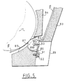
- la Fig.5 est une vue en coupe à plus grande échelle d'une variante du volet de guidage et de réception de documents;
- la Fig.6 est une vue partielle en coupe à plus grande échelle du dispositif détecteur d'images et du rouleau d'entraínement de documents qui font partie du dispositif de la Fig.1;
- la Fig.7 est une vue en coupe à plus grande échelle semblable à celle de la Fig.6 montrant une variante du dispositif anti-encrassement suivant l'invention;
- la Fig.8 est une vue en plan du dispositif anti-encrassement équipant le détecteur d'images de la Fig.7;
- la Fig.9 est une vue en coupe transversale à plus grande échelle d'un autre mode de réalisation du dispositif anti-encrassement suivant l'invention;
- la Fig.10 est une vue en coupe à plus grande échelle d'un écran de dispositif détecteur d'images qui présente un autre type de dispositif anti-encrassement suivant l'invention;
- la Fig.11 est une vue en coupe à plus grande échelle du dispositif anti-encrassement de l'écran du détecteur d'images du dispositif d'analyse de la Fig.1;
- la Fig.12 est une vue partielle en coupe transversale d'un dispositif d'analyse de supports d'information faisant partie d'un terminal de jeux et qui comporte un détecteur d'images équipé d'un dispositif de protection contre les poussières suivant l'invention;
- la Fig.13 est une vue à plus grande échelle, en coupe transversale du dispositif de protection suivant l'invention;
- la Fig.14 est une vue de côté suivant la
flèche 14 de la Fig.13 du dispositif de protection de la Fig.13; - la Fig.15 est une vue suivant la
flèche 15 de la Fig.13 du dispositif de la Fig.14; - la Fig.16 est une coupe à plus grande échelle suivant la ligne 16-16 de la Fig.15 montrant le profil d'une ailette du dispositif; et
- la Fig.16A est une vue en coupe correspondant à celle de la Fig.16 montrant une variante du profil des ailettes.
- Fig.1 is an exploded perspective view of the device for analyzing information carriers according to the invention;
- Fig.2 is an exploded perspective view of a detail of the device of Fig.1;
- Fig.3 is a cross-sectional view of the housing of the analysis device according to the invention, some parts of which have been removed;
- Fig.4 is a cross-sectional view of the assembled device;
- Fig.5 is a sectional view on a larger scale of a variant of the guide flap and document reception;
- Fig.6 is a partial sectional view on a larger scale of the image sensor device and the document drive roller which are part of the device of Fig.1;
- Fig.7 is a sectional view on a larger scale similar to that of Fig.6 showing a variant of the anti-fouling device according to the invention;
- Fig.8 is a plan view of the anti-fouling device fitted to the image detector of Fig.7;
- Fig.9 is a cross-sectional view on a larger scale of another embodiment of the anti-fouling device according to the invention;
- Fig.10 is a sectional view on a larger scale of an image detector device screen which has another type of anti-fouling device according to the invention;
- Fig.11 is a sectional view on a larger scale of the anti-fouling device of the screen of the image detector of the analysis device of Fig.1;
- Fig.12 is a partial cross-sectional view of a device for analyzing information media forming part of a gaming terminal and which includes an image detector equipped with a dust protection device according to the invention;
- Fig.13 is an enlarged view, in cross section of the protection device according to the invention;
- Fig.14 is a side view along
arrow 14 of Fig.13 of the protection device of Fig.13; - Fig.15 is a view along
arrow 15 of Fig.13 of the device of Fig.14; - Fig.16 is a section on a larger scale along line 16-16 of Fig.15 showing the profile of a fin of the device; and
- Fig.16A is a sectional view corresponding to that of Fig.16 showing a variant of the profile of the fins.
Le dispositif d'analyse de supports d'informations
ou documents représenté à la Fig.1, comporte un
boítier 1 en forme de canal de section générale en U à
bords évasés, réalisé en tôle métallique et fermé à ses
extrémités par des flasques 2 et 3 en matière plastique
par exemple fixés au boítier 1 par exemple par des vis 3a.The information media analysis system
or documents shown in Fig. 1, includes a
box 1 in the form of a channel section of general U-shaped
flared edges, made of sheet metal and closed to its
ends with
Les bords évasés 4 et 5 du boítier 1 comportent
ainsi qu'on le voit clairement à la Fig.3, des portions
inclinées 6,7 prolongeant chacune une aile verticale 8,9
du boítier et des rebords horizontaux 10,11.The
Cette forme évasée du boítier 1 facilite le montage du dispositif dans un ensemble plus important tel que par exemple un terminal de jeu ou autre.This flared shape of the housing 1 facilitates the mounting of the device in a larger assembly such as such as a gaming terminal or the like.
Dans le boítier ainsi constitué, est disposé un
détecteur d'images 15 de forme parallélépipédique allongée
s'étendant sur toute la longueur du boítier et constitué
d'une source de lumière linéaire (non représentée), des
moyens de focalisation de la lumière émise par la source
sur une paroi transparente 16 située en regard d'un
rouleau 17 d'entraínement de documents et des éléments
photo-sensibles (non représentés) de détection des faisceaux
lumineux provenant de la source linéaire lorsqu'ils
sont réfléchis par un document placé entre la paroi
transparente 16 et le rouleau 17.In the housing thus formed, is arranged a
Le détecteur d'images 15 comporte à ses extrémités
des plaques de montage 18,19 qui, comme on le voit
sur la plaque 18, comportent chacune une saillie 20,
coopérant avec une rainure inclinée ménagée dans chacune
des flasques d'extrémité 2,3 du boítier et dont seule la
rainure 21 du flasque 3 est visible, pour permettre le
montage du détecteur d'images 15 dans le boítier 1.The
Ainsi qu'on le voit bien à la Fig.3, à la partie
inférieure de chaque flasque 2,3 d'extrémité du boítier,
à proximité du fond 22 est fixé un ressort en épingle 23
monté sur un ergot 24 solidaire du flasque 3 correspondant
et comportant une branche 25 recourbée maintenue en butée
contre un pion 26 et destiné à venir en contact avec un
bord de la plaque 19 correspondante de montage du détecteur
d'images 15 pour assurer ainsi une suspension ou un
montage flottant du détecteur 15 dans le boítier 1.As can be seen in Fig. 3, in the part
bottom of each end flange 2.3 of the housing,
near the
Le détecteur d'images 15 est maintenu en place
dans le boítier par le rouleau d'entraínement 17, dont la
périphérie est revêtue, comme connu en soi d'une couche de
caoutchouc cellulaire 28 ou analogue.The
A chacune de ses extrémités, le rouleau 17
comporte des axes 29,30 pourvus de paliers correspondants
31,32 destinés à être reçus dans des encoches respectives
33,34 ménagées dans les bords supérieurs 35,36 des flasques
2 et 3 d'extrémité du boítier 1.At each of its ends, the
Les paliers 31,32 sont pourvus chacun d'un
verrou 37,38 d'immobilisation du rouleau 17 par rapport au
boítier 1.The
Ces verrous sont identiques, de sorte que seul
le plus visible sur le dessin, à savoir le verrou 38 va
être décrit.These locks are identical, so that only
most visible in the drawing, namely the
Il comporte une tige 39 solidaire d'un moyeu 40
formant l'une des pièces du palier correspondant et pourvu
de méplats 40a d'engagement des paliers dans les encoches
correspondants 33,34 des flasques 2,3 lorsque les verrous
sont en position de déverrouillage.It comprises a
A l'extrémité de la tige 39 opposée au moyeu est
prévu un trou 41 qui coopère avec un téton de blocage 42
prévu sur le flasque d'extrémité correspondant du boítier
1.At the end of the
Le verrouillage est assuré, après mise en place
des extrémités du rouleau 17 dans les encoches 33,34
correspondantes du boítier 1 par rotation des verrous
37,38 et engagement des tétons de blocage tels que le
téton 42 dans les trous correspondants tels que le trou 41
des verrous. Locking is ensured after installation
of the ends of the
L'élasticité des verrous 37,38 permet une légère
déformation de ceux-ci vers l'intérieur du boítier pour
permettre leurs engagements sur les tétons de blocage 42.The elasticity of the
Une languette 43 prévue à l'extrémité de chaque
verrou permet de faciliter sa manoeuvre de déblocage en
vue du dégagement du rouleau 17.A
Comme représenté à la Fig.4, lorsque le rouleau
17 est en place dans le boítier 1, il prend appui contre
la face transparente 16 du détecteur d'image 15 et provoque
la mise sous tension des ressorts de suspension du
détecteur d'image qui appliquent ainsi en permanence le
détecteur 15 contre le rouleau 17 grâce au montage coulissant
du détecteur 15 dans les rainures de guidage inclinées
21 du boítier.As shown in Fig. 4, when the
On obtient ainsi un contact permanent entre le détecteur et le rouleau, que ce soit en présence d'un document à analyser interposé entre ces deux éléments ou à vide.This gives permanent contact between the detector and the roller, whether in the presence of a document to be analyzed interposed between these two elements or empty.
L'axe d'extrémité 29 du rouleau 17 porte un
pignon 45 d'entraínement en rotation du rouleau qui
engrène avec le pignon de sortie 46 d'un réducteur 47 à
deux pignons 46 et 48 montés à rotation sur des axes fixés
aux flasques 2 du boítier 1. Le pignon d'entrée 48 du
réducteur est calé sur l'arbre de sortie 49 d'un moteur
électrique pas à pas 50 d'entraínement du rouleau fixé aux
flasques 2 par l'intermédiaire d'entretoises 51 venues de
matière qui ménagent entre elles un espace suffisant pour
loger des pignons du réducteur 47.The
Le palier 32 monté à l'extrémité du rouleau 17
opposé au pignon d'entraínement 45, comporte interposé
entre la pièce 40 formant moyeu pour le verrou 38 et une
rondelle 55 prenant appui sur un circlips 56 engagé dans
une rainure d'extrémité 57 de l'axe 30 du rouleau 17, une
rondelle ondulée 58 dont l'élasticité assure un montage
serré du palier 32 contre un épaulement correspondant 59
de l'axe 30 du rouleau, le palier 32 formant ainsi un
frein destiné à amortir les vibrations dues à l'entraínement
pas à pas du rouleau 17 transmises au rouleau 17 par
le pignon d'entraínement 45 de celui-ci.The
D'une manière analogue, ainsi qu'on l'a représenté
à la Fig.2, le pignon de sortie 46 du réducteur 47
est également monté sur son axe par l'intermédiaire d'une
rondelle ondulée 60, l'axe du pignon 46 étant constitué
par une tige filetée 61 comportant une partie lisse 62 de
réception du pignon 46 et une tête 63 de retenue axiale de
ce pignon.Analogously, as shown
in Fig. 2, the
Lorsque la tige filetée 61 est vissée dans un
trou taraudé correspondant ménagé dans le flasque 2 du
boítier 1, la rondelle ondulée 60 est comprimée et assure
le freinage en rotation du pignon 46 et ainsi l'amortissement
des vibrations qui lui sont transmises par le moteur
pas à pas 50.When the threaded
Dans le boítier est en outre disposé un volet
oscillant 65 de réception des documents après leur lecture
par le dispositif. Le volet oscillant 65 présente un
profil à peu près en forme d'équerre et s'étend lui aussi
sur toute la longueur du boítier entre les flasques 2 et
3 de celui-ci. Il comporte une surépaisseur longitudinale
66 dans laquelle sont ménagés des logements 67 de réception
de galets 68 montés à rotation sur des axes 69
engagés de façon amovible par encliquetage dans des fentes
70 prévues de part et d'autre des logements 67. Les galets
68 sont au nombre de quatre et sont régulièrement répartis
sur la longueur du volet oscillant 65.In the housing is further arranged a flap
oscillating 65 receiving documents after reading
by the device. The swinging
La surépaisseur longitudinale 66 du volet
oscillant 65 présente une face concave 71 en forme de
portion de cylindre coaxiale au rouleau 17 pour favoriser
le passage des documents.The
Le volet 65 est monté oscillant sur les flasques
d'extrémité 2 et 3 du boítier 1, par l'intermédiaire de
fourches 72 qui coopèrent chacune avec un axe 73 que l'on
aperçoit sur le flasque 3, tourné vers l'intérieur du
boítier 1. Le volet 65 est maintenu en position par des
ressorts en épingle 74 dont une branche 75 est recourbée
et accrochée sur un ergot 76 prévu sur le bord d'extrémité
du volet et dont l'extrémité opposée 77 est droite et
vient en butée avec un pion tel que 78 disposé à côté de
l'axe 73 sur le flasque 3 du boítier 1.The
Ainsi les ressorts 74 assurent l'application
permanente des galets 68 contre le rouleau 17.Thus the
Les galets 68 ont pour rôle d'une part d'accompagner
les documents entraínés par le rouleau 17, jusqu'au
bord arrière du document et d'autre part, lorsqu'un
document est libéré par le rouleau 17, de le ramener
contre le volet en coopération avce une butée qui sera
décrite en référence à la Fig.5.The role of the
Bien entendu, les éléments correspondants sont
prévus sur le flasque 2 pour assurer le montage oscillant
du volent 65 à ses deux extrémités.Of course, the corresponding elements are
provided on the flange 2 to ensure oscillating mounting
of
Ainsi qu'on peut le voir à la Fig.4, le dispositif
est complété par un guide 80 fixé par des entretoises
81 (Fig.1) dans le boítier 1 et qui est destiné à
faciliter l'introduction des documents entre le rouleau 17
et le détecteur d'images 15.As can be seen in Fig. 4, the device
is completed by a
Des capteurs 82, par exemple des capteurs à
infrarouges sont en outre disposés le long du guide 80
pour détecter la présence d'un document à l'entrée du
dispositif.
De façon avantageuse, ces capteurs sont au nombre de deux et leur distance est prévue de manière à permettre de déterminer la nature du document présenté au dispositif selon la largeur de ce document.Advantageously, these sensors are at number of two and their distance is predicted so that to determine the nature of the document presented to the device according to the width of this document.
Un tel agencement est décrit dans la demande de brevet français n° 92 10 642 déposée le 7 septembre 1992 par la Demanderesse et intitulée " Dispositif d'analyse de supports d'informations, notamment de bulletins de jeu ".Such an arrangement is described in the application for French patent n ° 92 10 642 filed on September 7, 1992 by the Applicant and entitled "Device for analyzing information media, including game reports. "
Au lieu d'être monté oscillant, le volet de
guidage et de réception des supports d'informations peut
être monté fixe dans le boítier du dispositif et les
galets qu'il porte peuvent être appliqués, contre le
rouleau 17 par des organes élastiques.Instead of being oscillating, the shutter
guiding and receiving information carriers can
be mounted fixed in the device housing and
rollers he wears can be applied against the
Une telle variante est représentée à la Fig.5.Such a variant is shown in Fig. 5.
Selon cette variante, le volet de guidage 83
fixé dans le boítier (non représenté) du dispositif
comporte comme le volet oscillant 65 de la Fig.1, une
surépaisseur 84 ayant une face concave 85 en forme de
portion de cylindre et dans cette surépaisseur des logements
86 pour des galets 87 dont le rôle est le même que
celui des galets 68.According to this variant, the
Les galets 87 sont montés chacun sur un axe 88.The
Dans la face du volet 83 opposée à la surépaisseur
84 sont ménagés des évidements 89 prévus aux emplacements
des galets 87 et débouchant dans les logements 86
correspndants.In the face of the
Un axe 88 d'un galet 87 est engagé dans des
gorges 90 creusées dans la paroi de fond de chaque évidement
89 de part et d'autre du logement 86 et appliqué au
fond desdites gorges par un ressort à lame 91 fixé dans le
fond de l'évidement par une vis 92 et ayant une branche 93
pliée à angle droit et ayant la forme d'une fourche, en
contact avec les extrémités du galet 86 en saillie par
rapport à celui-ci.A
Ainsi, chaque galet 86 est sollicité par son
ressort 91 en position sortie par rapport à la face
incurvée 85 et par conséquent contre le rouleau 17.Thus, each
Enfin, sur la Fig.5, on a représenté une butée
94 qui peut également être prévue dans le mode de réalisation
de la Fig.1 et qui sert en coopération avec les
galets 87 à permettre l'empilage des feuilles F de documents
traités à mesure qu'ils sortent du dispositif.Finally, in Fig.5, there is shown a
A cet effet, la butée 94 comporte un bord
incliné contre lequel les bords avant des feuilles F
butent pour être ensuite poussées contre la pile de
feuilles F déjà constituée contre le volet.For this purpose, the
Le dispositif d'analyse de documents qui vient
d'être décrit comporte également des moyens de traitement
des informations lues par le détecteur d'images et des
moyens de commande du moteur électrique pas à pas 50 pour
permettre l'exploration du document par balayages successifs
ligne après ligne.The document analysis device that comes
to be described also includes processing means
information read by the image sensor and
control means of the
Ces moyens qui ne font pas réellement partie de la présente invention, sont également décrits dans la demande de brevet précitée.These means which are not really part of the present invention are also described in the aforementioned patent application.
Dans le présent mode de réalisation, le dispositif
selon l'invention étant essentiellement appliqué à
l'analyse de bulletins et de reçus de jeux, le détecteur
d'images 15 est constitué par un lecteur optique aveugle
à au moins une couleur dans laquelle les informations
fixes sont imprimées sur le document à examiner et sensible
à d'autres couleurs afin de ne prendre en compte que
les informations variables de jeux et les informations
fixes de cadrage du document et de désignation du type de
jeu auquel il appartient, imprimées dans ces autres couleurs.In the present embodiment, the device
according to the invention being essentially applied to
analysis of game reports and receipts, the detector
of
Ce détecteur d'images est également décrit dans la demande de brevet français n° 92 10 642 citée plus haut.This image detector is also described in French patent application no. 92 10 642 cited more high.
On comprendra cependant que le dispositif d'analyse de supports d'informations suivant l'invention peut comporter un détecteur d'images de construction différente à condition toutefois qu'il soit de type linéaire permettant une exploration par défilement des documents qui lui sont soumis. It will however be understood that the device analysis of information carriers according to the invention may include a construction image detector different provided it is of the type linear allowing scrolling exploration of documents submitted to it.
On peut par exemple envisager de substituer au détecteur d'images décrit plus haut, un analyseur à lecture globale, d'analyse case par case d'un document et de reconnaissance positive des signes portés par le document, tel que ceux utilisés par exemple par les appareils de télécopie.We can for example consider replacing the image detector described above, a global reading, case by case analysis of a document and positive recognition of the signs carried by the document, such as those used for example by devices fax machine.
On va maintenant décrire en référence aux Fig.6 à 11, un dispositif d'analyse de supports d'informations dont le détecteur d'images est pourvu d'un dispositif anti-encrassement.We will now describe with reference to Fig. 6 at 11, a device for analyzing information carriers whose image detector is provided with a device anti-fouling.
Selon ce mode de réalisation, le détecteur
d'images désigné par la référence générale 115 est constitué
comme représenté plus en détail à la Fig.6, d'une
source de lumière comprenant des diodes électroluminescentes
116 auxquelles sont associés des organes 117 de
focalisation et de filtrage de la lumière destinés à
focaliser les faisceaux 118 sur une paroi transparente 119
ou écran du boítier du détecteur contre laquelle doit être
appliquée la face d'un document à analyser (non représenté).According to this embodiment, the detector
of images designated by the
En regard de la zone de focalisation 120 des
faisceaux émis par les diodes électroluminescentes 116,
sont disposés des conducteurs de lumière 121 de transmission
des faisceaux vers des éléments photosensibles 122.Next to the
La paroi transparente 119 du détecteur d'images
115 et un rouleau 123 d'entraínement des documents correspondant
au rouleau 17 de la Fig.1 sont en contact l'un
avec l'autre dans une zone légèrement décalée par rapport
aux axes optiques des conducteurs de lumière 121.The
La paroi transparente 119 et la surface extérieure
du rouleau 123 définissent ainsi un espace 130 en
forme de coin qui facilite l'introduction des documents
mais qui présente l'inconvénient d'accumuler des poussières
pouvant tomber de l'extérieur du dispositif, par
exemple en accompagnant les documents introduits dans
celui-ci.The
Par ailleurs, les documents traités viennent recevoir souvent de l'encre ou un autre produit qui risque de s'étaler sur la paroi transparente par frottement de celle-ci avec le document.Furthermore, the documents processed come from often receive ink or other hazardous product to spread on the transparent wall by friction of this one with the document.
L'accumulation de poussière d'encre et autre
dans l'espace 130 entraíne la formation d'un dépôt dans la
zone de focalisation 120 de la lumière émise par les
sources 116, détériorant ainsi les propriétés de transmission
des images éclairées par les sources sur les documents
analysés vers les éléments photosensibles 122 destinés
à transformer ces images en signaux susceptibles
d'être ensuite traités par des moyens numériques (non
représentés).Accumulation of ink dust and the like
in
Afin de remédier à cet inconvénient, la paroi
transparente ou écran 119 du détecteur d'images 115 présente
dans la région de la zone de focalisation 120, une
découpe 132 en forme de gradin ménagée dans l'épaisseur de
la matière de ladite paroi transparente.In order to overcome this drawback, the wall
transparent or
La découpe 132 forme le long du rouleau d'entraínement
123, une rainure axiale qui présente une paroi
133 de forte pente et une paroi de faible pente 134 à peu
près au milieu de laquelle se situe la zone de focalisation
120.The
On voit donc que grâce à cet agencement, la
paroi extérieure du rouleau 123 se trouve légèrement éloignée
de la surface de la paroi transparente 119 dans la
région de la zone de focalisation 120.So we see that thanks to this arrangement, the
outer wall of
Ainsi, la poussière a moins tendance à s'accumuler
dans cette zone et la transmission de la lumière
provenant de source 116, vers les éléments photosensibles
122 s'en trouve améliorée.Dust is less likely to collect
in this area and the transmission of light
from
Sur les Fig.7 et 8, on a représenté un autre
mode de réalisation de l'invention dans lequel la paroi
transparente 119 du détecteur d'images 115 est recouverte
d'un cache 135 de matière opaque qui forme également dans
la région de la zone de focalisation 120 un gradin 136
avec la partie 137 de la surface non recouverte de la
paroi transparente 119.In Figs. 7 and 8, another
embodiment of the invention in which the wall
transparent 119 of the
L'effet du gradin 136 obtenu par recouvrement
d'une partie de la paroi transparente 119 par le cache
opaque 135 est analogue à celui obtenu par le creusement
de la rainure 132 du mode de réalisation décrit en référence
à la Fig.6.The effect of
On voit en particulier sur la Fig.8, que l'écran
135 s'étend sur pratiquement toute la longueur de la paroi
transparente 119 du dispositif détecteur 115.We see in particular in Fig. 8, that the
Le mode de réalisation représenté aux Fig.7 et
8 dans lequel un cache opaque 135 est collé sur la surface
de la paroi transparente 119 présente en outre l'avantage
d'éviter que de la lumière parasite n'atteigne les éléments
photosensibles 122. Ceci permet d'obtenir des signaux
en provenance des documents à analyser plus précis.The embodiment shown in Fig. 7 and
8 in which an
Le cache 135 est fixé sur la paroi transparente
par collage.The
La Fig.9 est une vue en coupe à plus grande
échelle d'un autre mode de réalisation de la paroi
transparente 119 du dispositif détecteur d'images 115 de
la Fig.6 dans laquelle une rainure longitudinale en forme
de gradin 140 analogue à la rainure 132 du dispositif de
la Fig.6 est ménagée le long de l'un des bords longitudinaux
de la paroi 119.Fig. 9 is an enlarged sectional view
scale of another embodiment of the wall
transparent 119 of the
La Fig.10 montre une paroi transparente analogue
à celle de la Fig.9, le long de l'un des bords longitudinaux
de laquelle est ménagé un gradin 141 à parois respectivement
parallèles aux côtés et aux faces de la plaque
119 constituant la paroi transparente.Fig. 10 shows a similar transparent wall
to that of Fig. 9, along one of the longitudinal edges
from which a
La Fig.11 est une vue à plus grande échelle de
la paroi transparente du dispositif détecteur d'images
représenté à la Fig.6, dont la rainure en gradin 132 est
ménagée dans une zone intermédiaire de la surface de la
paroi transparente 119 en contact avec le rouleau d'entraínement
123, le bord de faible pente 134 de ce gradin
s'étendant de part et d'autre de la zone de focalisation
120 (Fig.6).Fig. 11 is an enlarged view of
the transparent wall of the image detection device
shown in Fig. 6, the stepped
La description qui va suivre faite en référence aux Fig.12 à 16A se rapporte à un dispositif de protection contre la poussière et les particules extérieures pouvant équiper le détecteur d'images du dispositif d'analyse suivant l'invention.The following description made with reference in Fig. 12 to 16A refers to a protection device against dust and external particles which may equip the image detector with the analysis device according to the invention.
En se référant à la Fig.12, on voit que l'invention est appliquée à un dispositif détecteur d'images qui fait partie d'un dispositif d'analyse de supports d'informations entrant dans la constitution d'un terminal de jeux tel que celui décrit dans la demande de brevet français n° 92 11 275 déposée le 22 septembre 1992 par la Demanderesse.Referring to Fig. 12, it can be seen that the invention is applied to an image sensing device which is part of a device for analyzing information carriers entering into the constitution of a gaming terminal such as that described in French patent application no. 92 11 275 filed on September 22, 1992 by the Applicant.
Ce détecteur d'images comporte une série de
sources lumineuses, des moyens de focalisation de la
lumière émise par les sources sur une paroi transparente
216 du boítier du détecteur et des éléments photosensibles
de réception des signaux émis par les sources lumineuses.This image detector has a series of
light sources, means for focusing the
light emitted by sources on a
La paroi transparente 216 du détecteur 215 est
en contact avec un rouleau 217 d'entraínement de documents.The
Le détecteur d'images 215 est disposé dans le
boítier 201 de façon inclinée.
La paroi transparente 216 du détecteur d'images
215 et le rouleau 217 d'entraínement des documents sont en
contact l'un avec l'autre et définissent ainsi un espace
220 en forme de coin qui facilite l'introduction de document
mais qui présente l'inconvénient d'accumuler des
poussières pouvant tomber de l'extérieur du dispositif par
exemple en accompagnant les documents introduits dans
celui-ci.The
L'accumulation de poussières dans l'espace 220
entraíne un dépôt de celles-ci dans la zone de focalisation
de la lumière émise par les sources du détecteur
d'images, détériorant ainsi les propriétés de transmission
des images éclairées par les sources sur les documents
analysés vers les éléments sensibles du détecteur qui sont
destinés à transformer les images en signaux susceptibles
d'être ensuite traités par des moyens numériques (non
représentés).Dust accumulation in
Dans le mode de réalisation représenté à la
Fig.12, le dispositif d'analyse est protégé à sa partie
supérieure par un cache 222 qui présente des fentes 223 et
224 pour l'entrée et la sortie des documents traités ainsi
qu'une zone centrale 225 à partir de laquelle s'étendent
des ailettes 226 régulièrement espacées. Les ailettes 226
ont un profil qui épouse la forme du rouleau d'entraínement
217 permettant d'éviter qu'un document acheminé par
le rouleau 217 n'ait tendance à rebrousser chemin vers
l'entrée du dispositif.In the embodiment shown in
Fig. 12, the analysis device is partially protected
upper by a
Sur le détecteur d'images 215 est monté, dans le
prolongement de la fente d'entrée 223 du cache 222, un
dispositif 230 de protection contre la poussière représenté
plus en détail aux Fig.13 à 15.On the
Sur la Fig.13, on voit que le dispositif 230 de
protection contre la poussière comprend un profilé 231 en
équerre allongée dont une première aile 232 porte une
série d'ailettes transversales 233 qui définissent des
passages 234 destinés à favoriser la chute des particules
de poussière qui pénètrent dans le dispositif de lecture
de documents par l'entrée 223. La chute des particules de
poussière dans les passages 234 se fait par gravité le
long d'une paroi 235 du détecteur d'images perpendiculaire
à sa paroi transparente 216. In Fig. 13, it can be seen that the
Le profilé 232 comporte une autre aile 236
appliquée sur le bord de la paroi transparente 216 du
détecteur d'images 215 et sur laquelle sont prévues des
nervures 237 de hauteur décroissante entre l'entrée 223 du
dispositif et la surface de la paroi transparente 216 du
détecteur d'images, ces nervures qui prolongent chacune
une ailette transversale 233 s'étendant parallélement à la
direction de déplacement des documents et assurant le
guidage des documents vers l'espace 220 ménagé entre la
paroi transparente 216 et le rouleau d'entraínement 217.
Le dispositif de protection contre la poussière sert également de support pour un circuit imprimé 238 de détection de la présence d'un document qui porte des photodiodes 239,240 disposées à une distance déterminée l'une de l'autre pour détecter la présence d'un document présenté à l'entrée du dispositif.The dust protection device also serves as support for a 238 printed circuit detection of the presence of a document which carries 239,240 photodiodes arranged at a determined distance each other to detect the presence of a document presented at the entrance to the device.
La fixation du circuit imprimé 238 sur le dispositif
230 de protection contre les poussières est assurée
par des doigts élastiques fendus 241 venus de matière avec
des ailettes transversales 233 solidaires de l'aile 231 du
profilé 230. Les doigts fendus 241 coopèrent par enclenchement
avec des trous 242 ménagés dans le circuit imprimé
238.The fixing of the printed
Pour recevoir le circuit imprimé 238, les ailettes
233 comportent des découpes 243 qui constituent ensemble
un logement pour le circuit imprimé.To receive the printed
Les photodiodes 239 et 240 sont montées sur la
tranche du circuit imprimé 238 et sont disposées chacune
entre deux ailettes voisines 233 comme cela apparaít
clairement à la Fig.15.
Le logement pour le circuit imprimé 238 défini
par les découpes 243 des ailettes transversales 233, fait
avec l'aile 231 du profilé 230, un angle précis permettant
d'assurer un positionnement correct des diodes 239 par
rapport à la direction de pénétration des documents dans
le dispositif d'analyse.The housing for the defined 238 printed circuit
by the
Le dispositif de protection contre les poussières
est fixé au boítier du détecteur d'images 215 ou plus
précisément à la paroi 235 de celui-ci par exemple au
moyen d'agrafes (non représentées) et qui sont engagées
dans des orifices 245 se trouvant en regard d'orifices
correspondants prévus dans la paroi 235 du boítier du
détecteur d'images (non représenté).The dust protection device
is attached to the frame of the
Ainsi qu'on peut le voir en particulier à la
Fig.16, les bords supérieurs des ailettes transversales
233 et des nervures 237 qui les prolongent, ont un profil
246 convexe incurvé, destiné à faciliter la chute des
particules de poussière de part et d'autre de chacune des
ailettes 233 dans les passages 234.As can be seen in particular at the
Fig. 16, the upper edges of the
Selon la variante représentée à la Fig.16A, le
profil convexe 247 des ailettes 233 est un profil à deux
pentes permettant également de faciliter la chute des
particules dans chaque passage 234 défini entre deux
ailettes 233 voisines.According to the variant shown in Fig. 16A, the
En se reportant à nouveau à la Fig.12, on voit
que le fond du boítier 201 du dispositif d'analyse de
documents, est occupé par un corps 250 en mousse d'absorption
des poussières et de liquides qui tombent le long du
trajet défini par les passages 234 du dispositif de
protection 230 après avoir contourné le boítier du détecteur
d'images 215.Referring again to Fig. 12, we see
that the bottom of the
Sur la Fig.12, on voit également que les parois
du cache 222 qui définissent la fente 223 comportent un
prolongement 251 qui s'étend à proximité immédiate du
dispositif de protection 230, de sorte que les particules
de poussière pénétrant dans l'entrée 223 sont acheminées
directement dans les passages 234 ménagés entre les ailettes
transversales 233 du dispositif de protection 230. In Fig. 12, we can also see that the walls
of the
Grâce à un tel agencement, les particules de
poussière n'atteignent pratiquement pas la paroi transparente
216 du détecteur d'images 215, de sorte que l'espace
220 entre cette paroi transparente et le rouleau d'entraínement
217 reste exempt de poussière, la transmission des
données éclairées sur les documents traités par les
sources lumineuses du détecteur d'images, s'en trouvant
considérablement améliorée.Thanks to such an arrangement, the particles of
dust practically does not reach the
Claims (26)
- Device for the analysis of information supports, notably bulletins or receipts from games comprising means to introduce the support, means to read the information found on the support, means to process the information read on the support in view of their conversion into numerical data and their transmission, reading means comprising an image detector (15; 114; 215) in a lengthened form suspended in a box (1, 2, 3; 201) and with, at its extremities, assembly means (20) which work with additional assembly means (21) planned in the corresponding extremity walls (2, 3) of the box, means to drive the information supports in front of the image detector, comprising a roller (17) and an electric motor (50) to make the roller rotate, the device being characterised in that the said roller (17; 123; 217) is assembled in the walls of the extremity (2, 3) of the box by means of locks (37, 38) and ensure that the image detector is maintained (15; 115; 215) in the said box and in that the elastic organs (23) interposed between the image detector (15) and the box (22) ensure the application of a pressure between the image detector (15; 115; 215) and the roller both in the presence of information supports between the image detector (15; 115; 215) and the roller (17; 213; 217) and when empty.
- Analysis device according to claim 1 , characterised in that the device box has a section in the form of a wide-mouthed U which is closed at its extremities by flanges (2,3) in plastic material and in that the image detector (15) comprises at its extremities assembly plates (18, 19) fitted with ribs (20) which work with inclined grooves (21) which are fitted in the flanges at the extremity (2,3) of the box, the assembly plates (18, 19) and the inclined grooves (21) forming the additional assembly means for the image detector (15) in the box.
- Analysis device according to claim 2 characterised in that the roller (17) to drive the information supports comprises axes (29, 30) at its extremities fitted with bearings (31, 32) of which the locks are part (37, 38) and the extremity flanges (2, 3) of the box comprise grooves (33, 34) to house the bearings (31, 32) of the roller and the means (42) to block the locks (37, 38) in the locking position.
- Analysis device according to one of claims 2 and 3 characterised in that the said elastic means to apply the image detector (15) against the roller (17) are pin springs (23) assembled on catches (24) fitted on the extremity flanges (2, 3) of the box and each having a curved branch (25) which is held against a pion (26) which is solid with the corresponding flange, and destined to come in contact with the edge of the corresponding assembly plate (18, 19) of the image detector (15) to ensure thus that the detector (15) is suspended in the box (1).
- Analysis device according to one of claims 2 to 4 characterised by the fact that at least one of the bearings (32) of the roller (17) to drive the information supports comprises means (58) which form the brake destined to amortise vibrations to which the roller (17) is subject from the drive means (45, 47, 50).
- Analysis device according to one of claims 2 to 5 characterised in that each lock (37, 38) of the roller (17) comprises a rod which is solid with a hub (40) which is an integral part of the corresponding bearing (31, 32), the said rod (37, 38) having at its free extremity, blocking means (41) which are complementary to the blocking means (41) planned in the flanges at the extremity (2,3) of the box, whilst the hub (40) comprises flat parts (40a) to introduce the hub in the corresponding groove (33,34) of the said flange, in an unlocked position of the lock, the rods of the lock having an elasticity allowing for the engaging and release of the additional blocking means (41, 42).
- Analysis device according to claims 2 to 6 characterised in that a flap (65) is also planned assembled in the box (1, 2, 3) and destined for guiding and housing the information supports during and after their passage between the roller (17) and the image detector (15), the flap comprises a longitudinal extra thickness (66) with a concave face (71) in the form of a cylinder portion which is coaxial to the roller (17) and fitted with housing (67) to receive the rotary runners which are regularly distributed over its length.
- Analysis device according to claim 7 characterised by the fact that the flap (65) oscillates and by the fact that the rotary rollers (68) are assembled in their housing (67) by means of axes (69) engaged immovably, by ratcheting in slots (70) planned on one side and the other of the housing (67).
- Analysis device according to one of claims 7 and 8, characterised by the fact that the flap (65) is assembled oscillating in the box (1, 2, 3) by means of forks (72) which work with axes (73) planned on the flanges (2, 3) at the extremity of the box, with the interposition of recall springs (74) which provide the application of the rollers (68) against the driver roller (17) for the information supports.
- Analysis device according to claim 7, characterised by the fact that the guiding and reception flap (83) for the information supports is assembled fixed in the device box and by the fact that the rotary rollers (87) are assembled in their housing (86) and work with elastic organs (91) for the application of the said rollers (87) against the drive roller (17) for the information supports.
- Analysis device according to one of claims 7 to 10 characterised by the fact that the stopper means (94) are placed above the rollers (68; 87) to deflect the information supports (F) coming from the device and thus ensuring they are piled up against the flap (65, 83)
- Analysis device according to one of claims 2 to 11 characterised by the fact that the motor (50) to make the drive roller (17) rotate is a step motor and is assembled on one of the flanges at the extremity (2) of the box (1, 2, 3), its output shaft (49) being connected to a pinion (45) solid with the drive roller (17) by the intermediary of a reducer (47) whose outlet pinion (46) comprises means (60) forming a amortisation brake for vibrations coming from the electric motor (50).
- Analysis device according to one of claims I to 12 whose image detector (115) comprises a transparent screen (119) for the transmission of light from a light source (117) between an information source which is lit up by the source and a reading element (122) receiving the images of the information carried on the support, the screen being in contact in the transmission zone of the light with an organ (123) for the application of the information support against the said screen, the contact zone between the application organ and the screen forming a zone for the accumulation of dust and spreading ink or another product likely to be an obstacle to the transmission of the light to the reading element (122), characterised in that on the surface of the screen (119) is a tier (132; 136; 140; 141) forming an anti-crush device containing the transmission zone for the light and located in front of the contact zone between the screen and the application organ in the direction of the movement of the information support.
- Analysis device according to claim 13, characterised in that the tier (132; 140; 141) is made by fitting a groove in the thickness of the screen material.
- Analysis device according to claim 14 characterised in that the groove (132) has an edge (133) with a strong incline and an edge (134) with a slight incline containing the zone (120) for the transmission of light.
- Analysis device according to claim 15, characterised in that the groove (132) is made between the longitudinal edges of the screen.
- Analysis device according to claim 15, characterised in that the groove (140) is made along the longitudinal edge of the screen (119).
- Analysis device according to claim 14, characterised in that the tier (141) is made by fitting in the thickness of the material of the screen (119) a groove with edges which are respectively parallel to the edges and faces of the screen.
- Analysis device according to claim 13, characterised in that the tier (136) is formed by an opaque mask (135) fixed on the face of the screen (119) turned towards the organ (123) for the application of the information support against the said screen, the said mask (135) leaving the zone (120) for the transmission of light and the zone for contact with the application organ (123) to he discovered.
- Analysis device according to one of claims 1 to 19, characterised in that it comprises a protection device against dust and external particles for the transparent wall (216) of the image detector (215) comprising an organ (230) to guide the information supports which is adaptable on the image detector (215) box, the said guiding organ comprising a series of passages (234) laid transversely to the direction of the movement of the documents along the image detector (215) box to allow particles of dust to fall by gravity along the image detector (215) box before it reaches the transparent wall (216) of the latter.
- Analysis device according to claim 20, characterised in that the protection device comprises a profile at right angles (231) whereof a longitudinal wing (232) destined to be applied against a wall (235) of the neighbouring image detector (215) of its transparent wall (216) is fitted with small transverse wings (233) which define the said passages (34).
- Analysis device according to claim 21, characterised in that the other wing (236) of the profile (231) destined to be applied against the transparent wall (216) of the image detector (215) comprises inclined transverse ribs (237) which extend in parallel to the direction of the movement of the information supports to ensure their guiding, and each being an extension of a transverse wing (233).
- Analysis device according to one of claims 21 and 22, characterised in that the small transverse wings (233) which define the said passages (234) comprise cuts (243) to form a housing for a printed circuit (238) holding organs (239, 240) detecting the presence of information supports, by means of small transverse wings being fitted with fixing means (242) for the printed circuit, on the device.
- Analysis device according to claim 23, characterised in that the fixing means for the printed circuit (238) comprise elastic triggering organs (242) from material with the section of the corresponding small transverse wings.
- Analysis device according to one of claims 22 to 24, characterised in that the rib sections (237) to guide the documents destined to come into contact with the documents have a convex profile (246; 247) which is rounded or with two slopes, facilitating the fall of dust particles into the said transverse passages (234).
- Analysis device according to one of claims 20 to 25, characterised in that an ahsorption plug (250) for dust and liquids is placed below the transverse passages (234) to receive the dust and liquids falling through the said passages.
Applications Claiming Priority (6)
| Application Number | Priority Date | Filing Date | Title |
|---|---|---|---|
| FR9211112 | 1992-09-17 | ||
| FR9211112A FR2695744B1 (en) | 1992-09-17 | 1992-09-17 | Improved device for analyzing information carriers. |
| FR9216008 | 1992-12-31 | ||
| FR9216008A FR2700028B1 (en) | 1992-12-31 | 1992-12-31 | Anti-fouling device, in particular for image detector. |
| FR9300215A FR2700400B1 (en) | 1993-01-13 | 1993-01-13 | Device for protection against dust and external particles, in particular for image detector. |
| FR9300215 | 1993-01-13 |
Publications (2)
| Publication Number | Publication Date |
|---|---|
| EP0588695A1 EP0588695A1 (en) | 1994-03-23 |
| EP0588695B1 true EP0588695B1 (en) | 1998-05-27 |
Family
ID=27252657
Family Applications (1)
| Application Number | Title | Priority Date | Filing Date |
|---|---|---|---|
| EP93402201A Expired - Lifetime EP0588695B1 (en) | 1992-09-17 | 1993-09-09 | Improved device for the analysis of information supports |
Country Status (10)
| Country | Link |
|---|---|
| US (1) | US5468943A (en) |
| EP (1) | EP0588695B1 (en) |
| JP (1) | JPH06231293A (en) |
| CN (1) | CN1033879C (en) |
| AT (1) | ATE166735T1 (en) |
| AU (1) | AU669383B2 (en) |
| DE (1) | DE69318785T2 (en) |
| DK (1) | DK0588695T3 (en) |
| ES (1) | ES2118204T3 (en) |
| GR (1) | GR3027631T3 (en) |
Families Citing this family (9)
| Publication number | Priority date | Publication date | Assignee | Title |
|---|---|---|---|---|
| US6043908A (en) * | 1997-01-06 | 2000-03-28 | Brother Kogyo Kabushiki Kaisha | Image reader for facsimile machine |
| US5864410A (en) * | 1997-04-01 | 1999-01-26 | Storm Technology, Inc. | Peripheral bus powered document scanning device |
| US6552828B1 (en) * | 1999-07-01 | 2003-04-22 | Cyberscan Technology, Inc. | Precision deep input guide clip for document scanners and document scanner incorporating same |
| US7002715B2 (en) * | 2002-02-08 | 2006-02-21 | Portable Peripheral Co., Ltd. | Paper pressing device for a scanner |
| JP4174282B2 (en) * | 2002-10-01 | 2008-10-29 | キヤノン株式会社 | Image reading device |
| JP2007194820A (en) * | 2006-01-18 | 2007-08-02 | Brother Ind Ltd | Image sensor, support member, image sensor unit, and image reading apparatus |
| CN202931448U (en) * | 2012-10-11 | 2013-05-08 | 光宝电子(广州)有限公司 | Bearing part and image scanning device |
| CN113976503B (en) * | 2021-12-03 | 2023-03-14 | 沧州职业技术学院 | Bioengineering image analysis input device |
| CN115100749B (en) * | 2022-08-25 | 2022-11-08 | 成都工业职业技术学院 | Ticket selling machine for railway transportation |
Family Cites Families (11)
| Publication number | Priority date | Publication date | Assignee | Title |
|---|---|---|---|---|
| US4036430A (en) * | 1976-05-13 | 1977-07-19 | Ebco Industries, Ltd. | Manually operable card reader |
| US4684792A (en) * | 1985-12-02 | 1987-08-04 | General Instrument Corp. | Multiple input compact ticket processor |
| JPS62252563A (en) * | 1986-04-25 | 1987-11-04 | Sharp Corp | Magnetic recording and reproducing device |
| US4788419A (en) * | 1986-09-19 | 1988-11-29 | International Totalizator Systems, Inc. | Ticket processing terminal with a single-cylinder ticket advancing mechanism |
| JPS6413849U (en) * | 1987-07-14 | 1989-01-24 | ||
| JP2684227B2 (en) * | 1989-04-19 | 1997-12-03 | 三菱電機株式会社 | Image sensor |
| US5153750A (en) * | 1989-05-23 | 1992-10-06 | Ricoh Company, Ltd. | Image reading apparatus having a contact type image sensor device |
| JP2766679B2 (en) * | 1989-08-04 | 1998-06-18 | キヤノン株式会社 | Document transport reading device |
| US4991949A (en) * | 1990-01-23 | 1991-02-12 | Comar, Inc. | Dust protection device for an image sensor |
| JPH0470053A (en) * | 1990-07-09 | 1992-03-05 | Mitsubishi Electric Corp | Close contact type image sensor |
| KR930003479B1 (en) * | 1990-12-28 | 1993-04-29 | 주식회사 신도리코 | Original jam removal device of fax transmission part |
-
1993
- 1993-09-09 DK DK93402201T patent/DK0588695T3/en active
- 1993-09-09 AT AT93402201T patent/ATE166735T1/en not_active IP Right Cessation
- 1993-09-09 ES ES93402201T patent/ES2118204T3/en not_active Expired - Lifetime
- 1993-09-09 EP EP93402201A patent/EP0588695B1/en not_active Expired - Lifetime
- 1993-09-09 DE DE69318785T patent/DE69318785T2/en not_active Expired - Fee Related
- 1993-09-15 AU AU47350/93A patent/AU669383B2/en not_active Ceased
- 1993-09-15 US US08/121,503 patent/US5468943A/en not_active Expired - Fee Related
- 1993-09-17 JP JP5231851A patent/JPH06231293A/en active Pending
- 1993-09-17 CN CN93119203A patent/CN1033879C/en not_active Expired - Fee Related
-
1998
- 1998-08-12 GR GR980401809T patent/GR3027631T3/en unknown
Also Published As
| Publication number | Publication date |
|---|---|
| AU669383B2 (en) | 1996-06-06 |
| EP0588695A1 (en) | 1994-03-23 |
| DE69318785T2 (en) | 1998-11-05 |
| US5468943A (en) | 1995-11-21 |
| JPH06231293A (en) | 1994-08-19 |
| DK0588695T3 (en) | 1999-01-18 |
| ES2118204T3 (en) | 1998-09-16 |
| CN1033879C (en) | 1997-01-22 |
| CN1092192A (en) | 1994-09-14 |
| GR3027631T3 (en) | 1998-11-30 |
| AU4735093A (en) | 1994-03-24 |
| DE69318785D1 (en) | 1998-07-02 |
| ATE166735T1 (en) | 1998-06-15 |
Similar Documents
| Publication | Publication Date | Title |
|---|---|---|
| EP0589755A1 (en) | Game terminal | |
| EP0588695B1 (en) | Improved device for the analysis of information supports | |
| FR2849519A1 (en) | AUTOMATED DOOR FOR ALLOWING OR PROHIBITING ACCESS TO A TRANSPORTATION AREA OR VEHICLE, PARTICULARLY A BOARDING AREA OR AN AIRPLANE | |
| CH689603A5 (en) | Smoke detector. | |
| EP0163114A1 (en) | Reading head for markings on a document | |
| EP3263979B1 (en) | One-piece lens with driven wheel sector | |
| CA1101983A (en) | Document analysis device, in particular for fac- simile sender | |
| EP0459921B1 (en) | Display device | |
| FR2541482A1 (en) | DEVICE FOR COLLECTING MONAIE PARTS IN AUTOMATIC COLLECTION MACHINES | |
| WO2020187967A1 (en) | Detector for detecting the position of a door frame pin and door frame fitted with such a detector | |
| EP0047466B1 (en) | Tray for holding and classifying fiches and projector therefor | |
| FR2695744A1 (en) | Machine for analysing game coupons | |
| CH682775A5 (en) | Card reader. | |
| CA1271654A (en) | Two-ray access control system for pedestrians | |
| FR2781590A1 (en) | TRANSPORTATION TICKET PRINTING AND RECORDING MODULE | |
| EP4031867B1 (en) | Device for taking a sample of biological liquid | |
| EP0678835A1 (en) | Coin checker | |
| FR2953163A1 (en) | DEVICE FOR FACILITATING MANIPULATION OF A LOAD OF EDITING MEDIA IN AN EDITING SYSTEM, EDITING SYSTEM INCLUDING SUCH A DEVICE. | |
| EP1318487A1 (en) | Security device for card reader | |
| FR2700400A1 (en) | Machine for analysing game coupons | |
| FR2700028A1 (en) | Machine for analysing game coupons | |
| EP0116256A1 (en) | Enclosure such as a garage, with an up-and-over door actuating a sliding-gate | |
| BE897084R (en) | DEVICE FOR MONITORING THE PAID PARKING TIME OF MOTOR VEHICLES | |
| EP0693203A1 (en) | Improved device for scanning data media, particularly game slips | |
| FR3126011A1 (en) | Extension device for a door frame and detection system |
Legal Events
| Date | Code | Title | Description |
|---|---|---|---|
| PUAI | Public reference made under article 153(3) epc to a published international application that has entered the european phase |
Free format text: ORIGINAL CODE: 0009012 |
|
| AK | Designated contracting states |
Kind code of ref document: A1 Designated state(s): AT BE CH DE DK ES FR GB GR IE IT LI LU MC NL PT SE |
|
| 17P | Request for examination filed |
Effective date: 19940729 |
|
| GRAG | Despatch of communication of intention to grant |
Free format text: ORIGINAL CODE: EPIDOS AGRA |
|
| 17Q | First examination report despatched |
Effective date: 19971014 |
|
| GRAG | Despatch of communication of intention to grant |
Free format text: ORIGINAL CODE: EPIDOS AGRA |
|
| GRAH | Despatch of communication of intention to grant a patent |
Free format text: ORIGINAL CODE: EPIDOS IGRA |
|
| GRAH | Despatch of communication of intention to grant a patent |
Free format text: ORIGINAL CODE: EPIDOS IGRA |
|
| GRAA | (expected) grant |
Free format text: ORIGINAL CODE: 0009210 |
|
| AK | Designated contracting states |
Kind code of ref document: B1 Designated state(s): AT BE CH DE DK ES FR GB GR IE IT LI LU MC NL PT SE |
|
| REF | Corresponds to: |
Ref document number: 166735 Country of ref document: AT Date of ref document: 19980615 Kind code of ref document: T |
|
| REG | Reference to a national code |
Ref country code: CH Ref legal event code: EP |
|
| ITF | It: translation for a ep patent filed |
Owner name: JACOBACCI & PERANI S.P.A. |
|
| GBT | Gb: translation of ep patent filed (gb section 77(6)(a)/1977) |
Effective date: 19980528 |
|
| REF | Corresponds to: |
Ref document number: 69318785 Country of ref document: DE Date of ref document: 19980702 |
|
| REG | Reference to a national code |
Ref country code: IE Ref legal event code: FG4D Free format text: FRENCH |
|
| REG | Reference to a national code |
Ref country code: ES Ref legal event code: FG2A Ref document number: 2118204 Country of ref document: ES Kind code of ref document: T3 |
|
| REG | Reference to a national code |
Ref country code: PT Ref legal event code: SC4A Free format text: AVAILABILITY OF NATIONAL TRANSLATION Effective date: 19980727 |
|
| REG | Reference to a national code |
Ref country code: DK Ref legal event code: T3 |
|
| PLBE | No opposition filed within time limit |
Free format text: ORIGINAL CODE: 0009261 |
|
| STAA | Information on the status of an ep patent application or granted ep patent |
Free format text: STATUS: NO OPPOSITION FILED WITHIN TIME LIMIT |
|
| 26N | No opposition filed | ||
| PGFP | Annual fee paid to national office [announced via postgrant information from national office to epo] |
Ref country code: DE Payment date: 20000814 Year of fee payment: 8 |
|
| PGFP | Annual fee paid to national office [announced via postgrant information from national office to epo] |
Ref country code: CH Payment date: 20000815 Year of fee payment: 8 |
|
| PGFP | Annual fee paid to national office [announced via postgrant information from national office to epo] |
Ref country code: MC Payment date: 20000816 Year of fee payment: 8 Ref country code: DK Payment date: 20000816 Year of fee payment: 8 |
|
| PGFP | Annual fee paid to national office [announced via postgrant information from national office to epo] |
Ref country code: AT Payment date: 20000817 Year of fee payment: 8 |
|
| PGFP | Annual fee paid to national office [announced via postgrant information from national office to epo] |
Ref country code: SE Payment date: 20000821 Year of fee payment: 8 |
|
| PGFP | Annual fee paid to national office [announced via postgrant information from national office to epo] |
Ref country code: NL Payment date: 20000824 Year of fee payment: 8 |
|
| PGFP | Annual fee paid to national office [announced via postgrant information from national office to epo] |
Ref country code: IE Payment date: 20000829 Year of fee payment: 8 |
|
| PGFP | Annual fee paid to national office [announced via postgrant information from national office to epo] |
Ref country code: PT Payment date: 20000831 Year of fee payment: 8 |
|
| PGFP | Annual fee paid to national office [announced via postgrant information from national office to epo] |
Ref country code: GB Payment date: 20000901 Year of fee payment: 8 |
|
| PGFP | Annual fee paid to national office [announced via postgrant information from national office to epo] |
Ref country code: FR Payment date: 20000915 Year of fee payment: 8 |
|
| PGFP | Annual fee paid to national office [announced via postgrant information from national office to epo] |
Ref country code: ES Payment date: 20000919 Year of fee payment: 8 |
|
| PGFP | Annual fee paid to national office [announced via postgrant information from national office to epo] |
Ref country code: LU Payment date: 20000922 Year of fee payment: 8 |
|
| PGFP | Annual fee paid to national office [announced via postgrant information from national office to epo] |
Ref country code: GR Payment date: 20000928 Year of fee payment: 8 |
|
| PGFP | Annual fee paid to national office [announced via postgrant information from national office to epo] |
Ref country code: BE Payment date: 20001011 Year of fee payment: 8 |
|
| PG25 | Lapsed in a contracting state [announced via postgrant information from national office to epo] |
Ref country code: MC Free format text: LAPSE BECAUSE OF NON-PAYMENT OF DUE FEES Effective date: 20010909 Ref country code: LU Free format text: LAPSE BECAUSE OF NON-PAYMENT OF DUE FEES Effective date: 20010909 Ref country code: GB Free format text: LAPSE BECAUSE OF NON-PAYMENT OF DUE FEES Effective date: 20010909 Ref country code: DK Free format text: LAPSE BECAUSE OF NON-PAYMENT OF DUE FEES Effective date: 20010909 Ref country code: AT Free format text: LAPSE BECAUSE OF NON-PAYMENT OF DUE FEES Effective date: 20010909 |
|
| PG25 | Lapsed in a contracting state [announced via postgrant information from national office to epo] |
Ref country code: SE Free format text: LAPSE BECAUSE OF NON-PAYMENT OF DUE FEES Effective date: 20010910 Ref country code: IE Free format text: LAPSE BECAUSE OF NON-PAYMENT OF DUE FEES Effective date: 20010910 Ref country code: ES Free format text: LAPSE BECAUSE OF NON-PAYMENT OF DUE FEES Effective date: 20010910 |
|
| PG25 | Lapsed in a contracting state [announced via postgrant information from national office to epo] |
Ref country code: LI Free format text: LAPSE BECAUSE OF NON-PAYMENT OF DUE FEES Effective date: 20010930 Ref country code: GR Free format text: LAPSE BECAUSE OF NON-PAYMENT OF DUE FEES Effective date: 20010930 Ref country code: CH Free format text: LAPSE BECAUSE OF NON-PAYMENT OF DUE FEES Effective date: 20010930 Ref country code: BE Free format text: LAPSE BECAUSE OF NON-PAYMENT OF DUE FEES Effective date: 20010930 |
|
| BERE | Be: lapsed |
Owner name: INTERNATIONALE DES JEUX Effective date: 20010930 |
|
| PG25 | Lapsed in a contracting state [announced via postgrant information from national office to epo] |
Ref country code: PT Free format text: LAPSE BECAUSE OF NON-PAYMENT OF DUE FEES Effective date: 20020331 |
|
| PG25 | Lapsed in a contracting state [announced via postgrant information from national office to epo] |
Ref country code: NL Free format text: LAPSE BECAUSE OF NON-PAYMENT OF DUE FEES Effective date: 20020401 |
|
| GBPC | Gb: european patent ceased through non-payment of renewal fee |
Effective date: 20010909 |
|
| PG25 | Lapsed in a contracting state [announced via postgrant information from national office to epo] |
Ref country code: DE Free format text: LAPSE BECAUSE OF NON-PAYMENT OF DUE FEES Effective date: 20020501 |
|
| EUG | Se: european patent has lapsed |
Ref document number: 93402201.3 |
|
| REG | Reference to a national code |
Ref country code: CH Ref legal event code: PL |
|
| PG25 | Lapsed in a contracting state [announced via postgrant information from national office to epo] |
Ref country code: FR Free format text: LAPSE BECAUSE OF NON-PAYMENT OF DUE FEES Effective date: 20020531 |
|
| NLV4 | Nl: lapsed or anulled due to non-payment of the annual fee |
Effective date: 20020401 |
|
| REG | Reference to a national code |
Ref country code: DK Ref legal event code: EBP |
|
| REG | Reference to a national code |
Ref country code: FR Ref legal event code: ST |
|
| REG | Reference to a national code |
Ref country code: IE Ref legal event code: MM4A |
|
| REG | Reference to a national code |
Ref country code: PT Ref legal event code: MM4A Free format text: LAPSE DUE TO NON-PAYMENT OF FEES Effective date: 20020331 |
|
| NLV4 | Nl: lapsed or anulled due to non-payment of the annual fee |
Effective date: 20020401 |
|
| REG | Reference to a national code |
Ref country code: ES Ref legal event code: FD2A Effective date: 20021011 |
|
| PG25 | Lapsed in a contracting state [announced via postgrant information from national office to epo] |
Ref country code: IT Free format text: LAPSE BECAUSE OF NON-PAYMENT OF DUE FEES;WARNING: LAPSES OF ITALIAN PATENTS WITH EFFECTIVE DATE BEFORE 2007 MAY HAVE OCCURRED AT ANY TIME BEFORE 2007. THE CORRECT EFFECTIVE DATE MAY BE DIFFERENT FROM THE ONE RECORDED. Effective date: 20050909 |