EP0587663B1 - Systeme de suspension pour vehicules - Google Patents
Systeme de suspension pour vehicules Download PDFInfo
- Publication number
- EP0587663B1 EP0587663B1 EP92911436A EP92911436A EP0587663B1 EP 0587663 B1 EP0587663 B1 EP 0587663B1 EP 92911436 A EP92911436 A EP 92911436A EP 92911436 A EP92911436 A EP 92911436A EP 0587663 B1 EP0587663 B1 EP 0587663B1
- Authority
- EP
- European Patent Office
- Prior art keywords
- vehicle
- roll
- suspension
- chassis
- counteracting
- Prior art date
- Legal status (The legal status is an assumption and is not a legal conclusion. Google has not performed a legal analysis and makes no representation as to the accuracy of the status listed.)
- Expired - Lifetime
Links
- 239000000725 suspension Substances 0.000 title claims abstract description 107
- 230000033001 locomotion Effects 0.000 claims abstract description 26
- 230000003068 static effect Effects 0.000 abstract description 11
- 238000005096 rolling process Methods 0.000 description 3
- 125000006850 spacer group Chemical group 0.000 description 3
- 241001247986 Calotropis procera Species 0.000 description 2
- 230000000694 effects Effects 0.000 description 2
- 238000011068 loading method Methods 0.000 description 2
- 238000004519 manufacturing process Methods 0.000 description 2
- 230000004048 modification Effects 0.000 description 2
- 238000012986 modification Methods 0.000 description 2
- 239000003381 stabilizer Substances 0.000 description 2
- 230000004075 alteration Effects 0.000 description 1
- 238000005452 bending Methods 0.000 description 1
- 230000006835 compression Effects 0.000 description 1
- 238000007906 compression Methods 0.000 description 1
- 230000008878 coupling Effects 0.000 description 1
- 238000010168 coupling process Methods 0.000 description 1
- 238000005859 coupling reaction Methods 0.000 description 1
- 230000009977 dual effect Effects 0.000 description 1
- 230000006872 improvement Effects 0.000 description 1
- 238000010348 incorporation Methods 0.000 description 1
- 230000003019 stabilising effect Effects 0.000 description 1
Images

Classifications
-
- B—PERFORMING OPERATIONS; TRANSPORTING
- B60—VEHICLES IN GENERAL
- B60G—VEHICLE SUSPENSION ARRANGEMENTS
- B60G21/00—Interconnection systems for two or more resiliently-suspended wheels, e.g. for stabilising a vehicle body with respect to acceleration, deceleration or centrifugal forces
- B60G21/02—Interconnection systems for two or more resiliently-suspended wheels, e.g. for stabilising a vehicle body with respect to acceleration, deceleration or centrifugal forces permanently interconnected
- B60G21/04—Interconnection systems for two or more resiliently-suspended wheels, e.g. for stabilising a vehicle body with respect to acceleration, deceleration or centrifugal forces permanently interconnected mechanically
- B60G21/05—Interconnection systems for two or more resiliently-suspended wheels, e.g. for stabilising a vehicle body with respect to acceleration, deceleration or centrifugal forces permanently interconnected mechanically between wheels on the same axle but on different sides of the vehicle, i.e. the left and right wheel suspensions being interconnected
- B60G21/055—Stabiliser bars
-
- B—PERFORMING OPERATIONS; TRANSPORTING
- B60—VEHICLES IN GENERAL
- B60G—VEHICLE SUSPENSION ARRANGEMENTS
- B60G11/00—Resilient suspensions characterised by arrangement, location or kind of springs
- B60G11/02—Resilient suspensions characterised by arrangement, location or kind of springs having leaf springs only
- B60G11/10—Resilient suspensions characterised by arrangement, location or kind of springs having leaf springs only characterised by means specially adapted for attaching the spring to axle or sprung part of the vehicle
- B60G11/12—Links, pins, or bushes
- B60G11/125—Multiple-eye arrangements
-
- B—PERFORMING OPERATIONS; TRANSPORTING
- B60—VEHICLES IN GENERAL
- B60G—VEHICLE SUSPENSION ARRANGEMENTS
- B60G11/00—Resilient suspensions characterised by arrangement, location or kind of springs
- B60G11/32—Resilient suspensions characterised by arrangement, location or kind of springs having springs of different kinds
- B60G11/34—Resilient suspensions characterised by arrangement, location or kind of springs having springs of different kinds including leaf springs
-
- B—PERFORMING OPERATIONS; TRANSPORTING
- B60—VEHICLES IN GENERAL
- B60G—VEHICLE SUSPENSION ARRANGEMENTS
- B60G17/00—Resilient suspensions having means for adjusting the spring or vibration-damper characteristics, for regulating the distance between a supporting surface and a sprung part of vehicle or for locking suspension during use to meet varying vehicular or surface conditions, e.g. due to speed or load
- B60G17/02—Spring characteristics, e.g. mechanical springs and mechanical adjusting means
Definitions
- This invention relates to vehicle suspensions and especially, but not exclusively, to suspensions for heavy load-carrying vehicles, such as, trucks and other similar types of commercial vehicles.
- a known vehicle suspension in the form of a tandem axle suspension, is known from International Patent Application Number WO 90/13450 (ZETTER-BERGS INDUSTRI AB) and comprises suspension means including a pair of leaf spring sets mounting the axles and pivotally connected, at one end thereof and by a respective shackles and longitudinal arms at each opposed longitudinal side of the vehicle, to a transverse bar.
- This forms a stabiliser system acting upon the axle and vehicle chassis with forces which tend to keep the axle parallel with a plane defined by side beams of the vehicle frame.
- side tilting or roll
- each end of the transverse bar is provided with counteracting means including an arm rigidly attached at one end thereof to the transverse bar, with the other end of the arm being arranged to act indirectly, via a hydraulic cylinder, upon the frame or chassis of the vehicle.
- the hydraulic cylinders are capable of extending and retracting, thus acting upon the transverse bar, to adjust the height of the axle relative to the vehicle chassis in order to redistribute the load between this and the other, separately suspended axle of the vehicle.
- suspension means including a pair of leaf springs which extend longitudinally of an associated vehicle on respective opposed lateral sides thereof and each of which includes mounting means for attachment of the leaf spring to the vehicle; an axle attached to the leaf spring intermediate the ends thereof; and anti-roll means, or other stabilising means in the form of an anti-roll tube or bar, extending between and attached rigidly to each leaf spring at a point spaced from the axle and capable of rotational movement as a consequence of deflection of the suspension means during straight axle bounce motion.
- Such a transversely arranged anti-roll means neither bears nor creates any force when the vehicle suspension is undergoing so-called "straight axle, static bounce" motion, because the respective leaf springs on opposed lateral sides of the vehicle deflect by substantially the same amount and in the same direction.
- the components by which the anti-roll means is attached to the associated leaf springs and the anti-roll means itself are rotatably deflected by substantially the same amount.
- the leaf springs on each side of the vehicle deflect in different directions, such that the components by which the anti-roll means is attached to the leaf springs, attempt to rotate in different directions, thereby twisting along the length of the transverse anti-roll means. Resistance to this torsional strain creates, in turn, a moment in the leaf springs thereby stiffening-up their opposing movements during vehicle roll.
- the leaf springs are effectively stiffer during vehicle rolling motion than in straight axle, static bounce motion, due to this anti-roll effect.
- Such anti-roll means may also carry secondary suspension means in series or parallel with the suspension springs which effectively constitute primary suspension means, with the secondary suspension means softening the total rate of the overall suspension.
- Such secondary suspension means may be in any suitable form, such as leaf springs or air or elastomeric cushions, and can be positioned at various locations transversely of the vehicle. Such locations for the secondary suspension means may be in-line with the springs of the primary suspension means or outboard or inboard thereof.
- the inboard secondary suspension means may also be combined into a single unit, such as a spring.
- Another object of the present invention is to increase the spring rate of a suspension proportional to increased suspension spring deflection during straight axle, static bounce motion, thereby enabling the vehicle to carry heavier loads than previously.
- a further object of the invention is to reduce peak stresses in the leaves of a suspension spring, thus enabling the spring to carry a higher load without being overstressed.
- Yet a further object of the invention is to utilise the anti-roll means to achieve one or more of the above-mentioned objects of the inventive suspension.
- the presently inventive vehicle suspension is characterised by:
- Such alteration of the deflection and rate of the suspension means may be to stiffen the vehicle suspension or to effectively soften it.
- the counteracting means may be a positive stop to any rotation of the anti-roll means which is arranged transversely of the longitudinal axis of the vehicle.
- a counteracting force may be graduated to provide a gradually increasing force which may eventually terminate in such a positive stop.
- the rotation counteracting means may be associated directly with, say, a transverse bar or tube of the anti-roll means or, alternatively, with any associated bracketry or other associated components of such means.
- the counteracting means may be arranged to act directly between the anti-roll means and the frame or chassis of the vehicle or to act indirectly therebetween, for example, via another suspension component, such as a main leaf spring, connected to the vehicle frame or chassis.
- another suspension component such as a main leaf spring
- the suspension means comprises leaf springs on opposed sides of the associated vehicle and, the primary gain afforded by the inventive suspension is an increase in spring rate with increased spring leaf deflection obtainable in straight axle, static bounce deflections.
- the suspension can carry heavier loads than previously.
- the suspension is effectively higher rated for carrying heavier loads.
- An additional feature of this arrangement namely, by at least partially counteracting the bending movement on the springs, is that the peak stresses in the leaves of the springs can be reduced, this enabling the springs to carry greater loads without being overstressed.
- the counteracting resistance to any rotational movement which the anti-roll means undergoes during straight axle static bounce may be of any suitable form, such as, spring means comprising a helical spring or air spring, to provide a gradually increasing resistance to counteract such rotation, optionally terminating eventually in a positive stop.
- spring means comprising a helical spring or air spring
- the associated vehicle could be raised or lowered as a result of the changed rate of the associated suspension springs. For instance, if reversed when the suspension means if lightly loaded, this arrangement could be used to deflect any associated suspension springs to lower the vehicle, thereby aiding vehicle loading or coupling to a trailer.
- the counteracting resistance may provide a rigid stop between the component, such as, a resistance arm of the type described below, connected to the anti-roll means and the vehicle frame or chassis.
- the anti-roll means is connected transversely of the associated vehicle to leaf springs on opposed sides thereof, with the rotation counteracting means being n the form of an arm rigidly secured thereto and arranged to act against spring means associated with the vehicle chassis or frame.
- the arm may be attached to the anti-roll means, preferably in the form of an anti-roll bar or tube, as will be described in more detail hereinbelow.
- the counteracting means may comprise spring means, as described above, or a damper, hydraulic cylinder or other suitable device.
- spring means as described above, or a damper, hydraulic cylinder or other suitable device.
- One alternative could be for such means to be activated or controlled by an active or semi-active ride system.
- Another might be to use a resiliently flexible arm of sufficient stiffness to at least partially counteract rotation of the anti-roll means.
- such counteracting means acts directly or indirectly between the anti-roll means and the vehicle chassis or frame, to effectively stiffen the suspension means as a result of the consequential restoring couple or moment applied thereto.
- the counteracting means may be provided in the form of a preformed, unitary component, particularly when in the form of a resistance arm, which can be supplied as a so-called "add-on" for incorporation in an existing suspension.
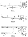
- a suspension for a vehicle wheel set (not shown) comprises a pair of leaf springs 11 which are mounted at 12 on the axle of an associated vehicle on opposed sides thereof and which are secured at front and rear ends thereof to the vehicle frame or chassis at X and Y by any suitable means.
- Anti-roll means in the form of an anti-roll device, here shown as a torsion bar or tube 13, has its ends connected rigidly to respective ends of the leaf springs 11. Secured to the anti-roll bar or tube 13 is a pair of forwardly-extending arms 14 upon whose forward ends 15 are supported respective helical springs 16 attached to the vehicle frame or chassis 17.
- the arms 14 are secured rigidly to the anti-roll bar or tube 13 such that when the latter rotates during straight axle, static bounce of the vehicle suspension, consequential vertical movement of the arms 14 is resisted, thereby at least partially counteracting such rotation of the anti-roll bar or tube 13.
- this counteracting resistance to rotation of the anti-roll bar or tube 13 creates a couple or moment in the associated leaf springs 11, thereby effectively stiffening that spring.
- the resistance arms 14 and associated springs 16 act directly between the anti-roll bar or tube 13 and the vehicle frame or chassis 17 and the counteracting resistance is graduated until on maximum vertical deflection of the arm 14, a positive stop is reached.
- such graduated resistance may be replaced by a discrete, positive stop at a predetermined vertical level of the arm 14.
- the leaf springs 11 are rendered effectively stiffer, or more highly rated, when carrying heavier loads.
- An additional feature of this effective couple or moment on the leaf spring 11 is that peak stresses in the leaves thereof can be reduced, thus enabling the springs to carry higher loads without being overstressed.
- the location of the sprung resistance arms 14 can be at any suitable location along the anti-roll bar or tube 13 and at any suitable angle thereto, depending upon the particular operating conditions of the associated vehicle.
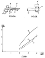
- FIG. 2 a diagrammatic representation of a leaf spring connected to the vehicle frame or chassis at its front ends at X, is shown in two operating conditions.
- the first under a light load represented by X', has the leaf spring in the configuration shown at 31, with a secondary suspension means in the form of a spring shown in an extended condition 36.
- the associated arm 34 is equivalent to the arm 14 of the first embodiment of Figures 1A and 1B and is secured between anti-roll means in the form of a transverse anti-roll bar or tube 33 and a bush 38 of a shackle indicated at 39.
- the other end of the shackle 39 is connected to the vehicle frame or chassis by a bush 38'' with the shackle acting as a resistance stop to constitute the counteracting means for the anti-roll bar or tube 33, whereby the resistance arm 34 and shackle 39 act directly between the anti-roll bar or tube 33 and vehicle frame or chassis.
- the primary suspension leaf spring Under a heavy load, as represented at Y', the primary suspension leaf spring is deflected upwardly into the condition shown at 31' and the anti-roll bar or tube rotates and moves into the position represented at 33'.
- the other end of the arm as shown at 34', is lowered relative to the spring 31', with the secondary suspension spring secured to the vehicle frame or chassis at 37 being deflected by compression under the increased load, as shown at 36', by a sufficient amount to bring the bush, as shown at 38' of the shackle, now shown at 39', back to where the shackle would have moved under extension of the primary suspension leaf spring end.
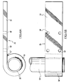
- FIG. 3A and 3B Such an arrangement could be applied in accordance with the present invention to create the second embodiment shown in Figures 3A and 3B, wherein primary suspension means, indicated generally at 40, is constituted by a pair of leaf springs 41 disposed on opposed sides of a vehicle chassis (also not shown) and connect thereto at their front ends at X. Opposed ends of an anti-roll bar or tube 43 are connected to respective arms 44 which, at one end, are connected to the vehicle chassis by shackles 49 and, at the other end, directly to the anti-roll bar or tube 43 at 46 at the adjacent end of the leaf springs 41.
- Secondary suspension means in the form of, say, a coil spring 47, is mounted upon the anti-roll bar or tube 43 to act in conjunction therewith.
- the secondary suspension means provided in this particular case by the coil spring 47, is equivalent to the secondary suspension spring 36, 36' of Figure 2.
- FIGS 4A and 4B there is shown a preformed unitary structure for use in a third embodiment of the present invention and comprising a pair (only one shown) of resistance arms 54 attached to an anti-roll bar tube 53.
- Each resistance arm 54 comprises a generally circular end portion 56 whose inner surface is welded to the outer surface of the anti-roll tube 53 at one end thereof.
- the resistance arm 54 also comprise a generally linear arm portion 55 which can be secured to an existing vehicle suspension by means of, for example, bolts passing through respective holes 58.
- Extra stiffness for each resistance arm 54 is provided by a weld 57 in the juncture between the end portion 56 and arm portion 55.
- This preformed unit comprising the pair of resistance arms 54 and associated anti-roll tube 53 can be readily secured, as described above, to the leaf springs of an existing vehicle suspension, to create the third embodiment of the present invention as shown in Figures 5A and 5B.
- the unit has the generally straight arm portion 55 of the resistance arm 54 secured by bolts 59 to a pair of leaf springs 61, 61' of an existing vehicle suspension.
- the resistance arm 54 acting directly between the anti-roll tube 53 and the existing vehicle suspension leaf springs 61, 61', and hence indirectly between the tube 53 and the frame or chassis (not shown) of the associated vehicle, the resistance to at least partially counteract rotational movement of the anti-roll tube 53 is transferred to the vehicle frame or chassis via the main leaf springs 61, 61'.
- These main vehicle suspension leaf spring resistance arms 54 can also increase the stiffness of and reduce stresses in the main springs locally, due to their contact therewith, in addition to any other counteracting means which may be provided.
- Such other counteracting means may be in the form of those discussed above in relation to the earlier embodiments of the inventive suspension.
- a further feature of this particular embodiment is that the resistance arms 54 can reduce the stresses in, and increase the spring rate locally of, the main leaf springs 61, 61' during rolling motions of the vehicle, by distributing the anti-roll effect from the anti-roll tube over a large section of the main leaf springs.
- Figure 6 is a graph of the results of those trials, representing angle of lean of the vehicle in degrees versus the speed of the vehicle in miles per hour.
- the vehicle fitted with the inventive suspension as represented by curve C, has a lower range of lean angles than the vehicle fitted with no anti-roll means or the vehicle fitted with conventional anti-roll means in the form of a torsion bar or tube.
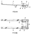
- the fourth embodiment of suspension in accordance with the present invention and as shown in Figure 7 comprises the anti-roll tube 53 and resistance arm 54 provided as the preformed unit, secured to a pair of main leaf springs 81, 81' connected in turn to one side of a vehicle frame or chassis (not shown). Such connection is effected by a clamping arrangement 82 which clamps the springs 81, 81' and arm portion 55 of the resistance arm 54 securely together.
- a similar arrangement is provided on the other side of the vehicle chassis or frame for the corresponding pair of main leaf springs (also not shown).
- a resilient spacer such as that shown at 83, may be provided between the two leaf springs 81 and 81'.
- Another resilient spacer 83' is provided between the clamping arrangement 82 and the upper main leaf spring 81'. Both resilient spacers 83, 83' assist in distributing the couple from the anti-roll tube 53 and arm 54 to the upper leaf spring 81'.
- the two leaf springs 81, 81' may be secured to the vehicle chassis or frame in any suitable manner, such as by means of the eye 84 i n respect of which associated shackles or bushes are not shown for reasons of clarity.
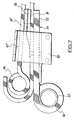
- a pair of leaf springs 91 arranged on opposed sides of the associated vehicle frame or chassis, are connected to the vehicle frame or chassis at X and Y and are each associated with two forms of resistance arm.
- the first resistance arm 94 is secured rigidly at one end to the corresponding end of anti-roll means in the form of an anti-roll bar 93.
- the other end of each resistance arm 94 is arranged to contact a rigid stop 95 which, in turn, is connected to the vehicle frame or chassis at 96, so that the resistance arm 94 and stop 95 act directly between the anti-roll bar 93 and the vehicle frame or chassis 96, when the bar 93 has rotated a sufficient amount for the arm 94 to contact the stop 95.
- Such rotation may be by a predetermined amount, depending upon operating requirements.
- the other resistance arm on each side of the vehicle frame or chassis 96 is shown at 97 and it too has one end connected to the anti-roll bar 93. Its other end is connected to the spring 91 by means of a clip and rubber bushes, as shown at 98.
- This arrangement represents a resilient connection between the forward end of the resistance arm 97 and the leaf spring 91, whereby there is some movement available between the arm 97, clip and rubber bushes 98 and leaf spring 91, whereby the resistance arms 97 and clip and bushes act indirectly, via the springs 91, between the anti-roll bar 93 and vehicle frame or chassis 96.
- this dual arrangement provides a combination of two forms of resistance arm in accordance with the invention.
- a purely rigid stop such as that represented by the stop 95, could be provided between the resistance arm and the vehicle frame or chassis, with the omission of the other resistance arm 97 and associated components 98.
- an existing anti-roll means such as an anti-roll tube or bar
- an existing anti-roll means can be adapted to provide suitable means, to act between the anti-roll means and the vehicle frame or chassis, for at least partially counteracting any rotation of the anti-roll means during straight axle static bounce motion of a vehicle suspension, in order to apply a restoring couple or moment to the suspension means, thereby stiffening the latter and effectively increasing the spring rate.
- inventive vehicle suspensions particularly the add-on anti-roll means/resistance arm unit of Figures 4A and 4B, include low manufacturing costs, low weight, no requirement for vehicle frame or chassis or suspension mounting bracket modifications, non-specialist manufacture and the removal of stress from the vehicle frame or chassis.
Landscapes
- Engineering & Computer Science (AREA)
- Mechanical Engineering (AREA)
- Vehicle Body Suspensions (AREA)
- Transition And Organic Metals Composition Catalysts For Addition Polymerization (AREA)
Claims (12)
- Suspension pour véhicule, comportant :des moyens de suspension comprenant deux ressorts à lames (11) qui s'étendent le long d'un véhicule associé, sur les côtés latéraux opposés respectifs de celui-ci, et qui présentent chacun des moyens de montage (X, Y) pour leur fixation au véhicule,un essieu (12) fixé au ressort à lame (11) entre les extrémités de celui-ci, etdes moyens antiroulis (13) qui s'étendent entre les ressorts à lames (11), qui sont fixés rigidement à ceux-ci en un point espacé de l'essieu (12) et qui sont aptes à décrire un mouvement rotatif à la suite d'un fléchissement des moyens de suspension pendant un mouvement de rebondissement rectiligne de l'essieu,
caractérisée par :des moyens de neutralisation comportant au moins un bras (14) dont une extrémité est fixée rigidement aux moyens antiroulis (13) tandis que l'autre extrémité est disposée de manière à agir sur le châssis (17) du véhicule, de sorte que lesdits moyens de neutralisation peuvent agir entre les moyens antiroulis (13) et le châssis (17) du véhicule,
moyennant quoi lorsque les moyens de suspension fléchissent pendant un mouvement de rebondissement rectiligne de l'essieu, les moyens de neutralisation agissent pour neutraliser au moins partiellement le mouvement rotatif des moyens antiroulis (13) qui en résulte, appliquant ainsi un couple ou un moment à chaque ressort à lame (11), modifiant par conséquent le fléchissement et la vitesse de rappel de chaque ressort à lame (11) et modifiant ainsi le fléchissement et la vitesse de rappel de la suspension. - Suspension pour véhicule selon la revendication 1, dans laquelle les moyens de neutralisation comportent une butée fixe.
- Suspension pour véhicule selon la revendication 1, dans laquelle les moyens de neutralisation sont progressifs afin de fournir une force de résistance progressivement croissante à l'encontre de la rotation des moyens antiroulis (13).
- Suspension pour véhicule selon la revendication 3, dans, laquelle les moyens de neutralisation progressifs aboutissent à une butée fixe.
- Suspension pour véhicule selon l'une quelconque des revendications précédentes, dans laquelle le bras (54) des moyens de neutralisation est disposé de manière à agir entre les moyens antiroulis (53) et le châssis (17) du véhicule par l'intermédiaire d'un autre élément de la suspension.
- Suspension pour véhicule selon la revendication 5, dans laquelle l'autre élément de suspension est un ressort à lame (61) relié au châssis (17) du véhicule.
- Suspension pour véhicule selon l'une quelconque des revendications 1 à 4 dans laquelle une extrémité (15) du bras (14) est disposée de manière à agir sur le châssis (17) du véhicule grâce à des moyens formant ressorts (16) disposés entre les deux, afin de fournir une force progressivement croissante à l'encontre de la rotation des moyens antiroulis (13).
- Suspension pour véhicule selon la revendication 7, dans laquelle les moyens formant ressorts (16) aboutissent à une butée fixe.
- Suspension pour véhicule selon l'une quelconque des revendications précédentes, dans laquelle le bras (14) est flexible comme un ressort.
- Suspension pour véhicule selon l'une quelconque des revendications précédentes, dans laquelle les moyens antiroulis (53) et le bras (54) forment une unité préformée apte à être associée à une suspension pour véhicule existante.
- Suspension pour véhicule selon l'une quelconque des revendications précédentes, dans laquelle les moyens antiroulis comprennent une barre ou un tube antiroulis (13) qui est disposé transversalement par rapport au châssis (17) du véhicule, les moyens de neutralisation étant disposés globalement au milieu de la barre ou du tube antiroulis (13).
- Suspension pour véhicules selon l'une quelconque des revendications précédentes, dans laquelle les moyens antiroulis comprennent une barre ou un tube antiroulis (13) qui est disposé transversalement par rapport au châssis (17) du véhicule, les moyens de neutralisation étant disposés à chaque extrémité de la barre ou du tube antiroulis (13), près du ressort à lame (11) correspondant.
Applications Claiming Priority (3)
| Application Number | Priority Date | Filing Date | Title |
|---|---|---|---|
| GB91124610 | 1991-06-10 | ||
| GB919112461A GB9112461D0 (en) | 1991-06-10 | 1991-06-10 | Vehicle suspension |
| PCT/GB1992/001039 WO1992022438A1 (fr) | 1991-06-10 | 1992-06-10 | Systeme de suspension pour vehicules |
Publications (2)
| Publication Number | Publication Date |
|---|---|
| EP0587663A1 EP0587663A1 (fr) | 1994-03-23 |
| EP0587663B1 true EP0587663B1 (fr) | 1998-04-22 |
Family
ID=10696402
Family Applications (1)
| Application Number | Title | Priority Date | Filing Date |
|---|---|---|---|
| EP92911436A Expired - Lifetime EP0587663B1 (fr) | 1991-06-10 | 1992-06-10 | Systeme de suspension pour vehicules |
Country Status (8)
| Country | Link |
|---|---|
| US (1) | US5507516A (fr) |
| EP (1) | EP0587663B1 (fr) |
| AT (1) | ATE165286T1 (fr) |
| AU (1) | AU1908792A (fr) |
| DE (1) | DE69225225T2 (fr) |
| ES (1) | ES2114939T3 (fr) |
| GB (1) | GB9112461D0 (fr) |
| WO (1) | WO1992022438A1 (fr) |
Families Citing this family (12)
| Publication number | Priority date | Publication date | Assignee | Title |
|---|---|---|---|---|
| SE503443C2 (sv) * | 1992-12-22 | 1996-06-17 | Volvo Ab | Bladfjäder för upphängning av en stel hjulaxel hos ett fordon |
| US6015158A (en) * | 1998-06-24 | 2000-01-18 | Timbren Industries Inc. | Heavy duty truck suspension |
| GB9913376D0 (en) * | 1999-06-10 | 1999-08-11 | Detroit Steel Products Co Inc | Air suspension anti-roll stabilisation system |
| US7048287B2 (en) * | 1999-06-10 | 2006-05-23 | Detroit Steel Products Co., Inc. | Air suspension anti-roll stabilization system |
| GB2363594B (en) * | 2000-04-07 | 2003-09-17 | Harvey Bailey Eng Ltd | Vehicle wheel suspension |
| EP1337408A1 (fr) * | 2000-11-28 | 2003-08-27 | Detroit Steel Products Co., Inc. | Suspension de vehicule a ressorts multilames avec barre antiroulis |
| US20060255556A1 (en) * | 2002-06-14 | 2006-11-16 | Reast John B | Leaf spring suspension systems and sub-assemblies therefor |
| GB0308572D0 (en) * | 2003-04-12 | 2003-05-21 | Detroit Steel Products Co Inc | Anti-roll leaf spring suspension |
| DE602004014871D1 (de) * | 2003-10-24 | 2008-08-21 | Nissan Motor | Einzelradaufhängung für ein Kraftfahrzeug |
| US8342487B2 (en) * | 2004-01-19 | 2013-01-01 | Standens Ltd. | Anti-roll leaf spring suspension |
| GB0420887D0 (en) | 2004-09-20 | 2004-10-20 | Detroit Steel Products Co Inc | Vehicle suspension handling stabilsation system |
| US10618364B2 (en) * | 2017-01-09 | 2020-04-14 | Rassini Suspensiones, S.A. De C.V. | Hybrid leaf spring arrangement for vehicle suspension system |
Family Cites Families (17)
| Publication number | Priority date | Publication date | Assignee | Title |
|---|---|---|---|---|
| FR332159A (fr) * | 1903-05-18 | 1903-10-17 | Thomas Georges Stevens | Mécanisme perfectionné pour produire une action simultanée et uniforme des ressorts de véhicules |
| DE266324C (fr) * | 1912-08-19 | |||
| US1378665A (en) * | 1919-05-20 | 1921-05-17 | Ford Peter Du | Shock-absorber |
| BE496699A (fr) * | 1947-08-04 | |||
| CH339508A (de) * | 1954-09-14 | 1959-06-30 | Leander Nilsson August | Federung an Fahrzeugen |
| DE1012533B (de) * | 1955-06-11 | 1957-07-18 | E H Carl F W Borgward Dr Ing | Abfederung fuer Kraftfahrzeuge |
| GB954123A (en) * | 1962-03-06 | 1964-04-02 | Vauxhall Motors Ltd | Motor vehicle suspensions |
| FR1362660A (fr) * | 1963-04-25 | 1964-06-05 | Citroen Sa Andre | Suspension à élasticité variable |
| US3491994A (en) * | 1967-09-08 | 1970-01-27 | Ford Motor Co | Leaf spring vehicle suspension |
| FR2154297B1 (fr) * | 1971-09-27 | 1975-02-21 | Citroen Sa | |
| US3860259A (en) * | 1973-12-03 | 1975-01-14 | Ford Motor Co | Rear suspension system for motor vehicle |
| US4094532A (en) * | 1977-05-16 | 1978-06-13 | Sway-A-Way Corporation | Torsion bar adjusting device |
| US4181324A (en) * | 1977-10-06 | 1980-01-01 | Hixon William K | Overload stabilizer unit for vehicle |
| FR2561997B1 (fr) * | 1984-04-03 | 1988-10-14 | Aerospatiale | Systeme de suspension pour un train de roues de vehicule a essieu rigide |
| US5007660A (en) * | 1989-01-17 | 1991-04-16 | The B. F. Goodrich Company | Suspension system |
| GB8906600D0 (en) * | 1989-03-22 | 1989-05-04 | Detroit Steel Products Co Inc | Vehicle suspension |
| SE464398B (sv) * | 1989-05-12 | 1991-04-22 | Zetterbergs Ind Ab | Anordning vid lastbilar |
-
1991
- 1991-06-10 GB GB919112461A patent/GB9112461D0/en active Pending
-
1992
- 1992-06-10 AU AU19087/92A patent/AU1908792A/en not_active Abandoned
- 1992-06-10 WO PCT/GB1992/001039 patent/WO1992022438A1/fr active IP Right Grant
- 1992-06-10 ES ES92911436T patent/ES2114939T3/es not_active Expired - Lifetime
- 1992-06-10 EP EP92911436A patent/EP0587663B1/fr not_active Expired - Lifetime
- 1992-06-10 US US08/162,204 patent/US5507516A/en not_active Expired - Lifetime
- 1992-06-10 AT AT92911436T patent/ATE165286T1/de not_active IP Right Cessation
- 1992-06-10 DE DE69225225T patent/DE69225225T2/de not_active Expired - Fee Related
Also Published As
| Publication number | Publication date |
|---|---|
| US5507516A (en) | 1996-04-16 |
| EP0587663A1 (fr) | 1994-03-23 |
| GB9112461D0 (en) | 1991-07-31 |
| WO1992022438A1 (fr) | 1992-12-23 |
| DE69225225D1 (de) | 1998-05-28 |
| AU1908792A (en) | 1993-01-12 |
| ES2114939T3 (es) | 1998-06-16 |
| DE69225225T2 (de) | 1999-01-07 |
| ATE165286T1 (de) | 1998-05-15 |
Similar Documents
| Publication | Publication Date | Title |
|---|---|---|
| JP3200435B2 (ja) | 車両の車輪組用懸架システム | |
| US5924712A (en) | Dual trailing arm vehicle suspension | |
| CA2030027C (fr) | Suspension a bras raidisseur | |
| US6672605B2 (en) | Vehicle suspension systems | |
| EP1789268B1 (fr) | Suspension de vehicule | |
| US6375203B1 (en) | Front air spring suspension with leading arm trailing and V-link | |
| US7798507B2 (en) | Vehicle suspension apparatus | |
| US4781364A (en) | Elastic beam-torsion rod connection | |
| US6390485B1 (en) | Vehicle suspension | |
| US20090085318A1 (en) | Vehicle leaf spring suspension with radius arms | |
| EP0587663B1 (fr) | Systeme de suspension pour vehicules | |
| KR100433326B1 (ko) | 제로 롤 현가 시스템 및 그 제공 방법 | |
| EP1185428B1 (fr) | Systeme de stabilisation anti-roulis a suspension pneumatique | |
| US4632423A (en) | Structure for mounting stabilizer in vehicle suspension | |
| WO2006121438A2 (fr) | Suspension de vehicule a ressorts a lames pourvus de bras longitudinaux | |
| EP1910108B1 (fr) | Suspension de roue individuelle | |
| US7048287B2 (en) | Air suspension anti-roll stabilization system | |
| AU724085C (en) | Dual trailing arm vehicle suspension | |
| AU703820B2 (en) | Vehicle suspension | |
| JPH0653454B2 (ja) | 車輛用サスペンシヨンのスタビライザ取付構造 | |
| MXPA96003498A (en) | Vehic suspension | |
| KR20010059110A (ko) | 자동차의 세미 트레일링 아암 타입 현가장치 |
Legal Events
| Date | Code | Title | Description |
|---|---|---|---|
| PUAI | Public reference made under article 153(3) epc to a published international application that has entered the european phase |
Free format text: ORIGINAL CODE: 0009012 |
|
| 17P | Request for examination filed |
Effective date: 19931112 |
|
| AK | Designated contracting states |
Kind code of ref document: A1 Designated state(s): AT BE CH DE DK ES FR GB GR IT LI LU MC NL SE |
|
| 17Q | First examination report despatched |
Effective date: 19950724 |
|
| APAB | Appeal dossier modified |
Free format text: ORIGINAL CODE: EPIDOS NOAPE |
|
| APBJ | Interlocutory revision of appeal recorded |
Free format text: ORIGINAL CODE: EPIDOS IRAPE |
|
| GRAG | Despatch of communication of intention to grant |
Free format text: ORIGINAL CODE: EPIDOS AGRA |
|
| GRAG | Despatch of communication of intention to grant |
Free format text: ORIGINAL CODE: EPIDOS AGRA |
|
| GRAH | Despatch of communication of intention to grant a patent |
Free format text: ORIGINAL CODE: EPIDOS IGRA |
|
| GRAH | Despatch of communication of intention to grant a patent |
Free format text: ORIGINAL CODE: EPIDOS IGRA |
|
| GRAA | (expected) grant |
Free format text: ORIGINAL CODE: 0009210 |
|
| ITF | It: translation for a ep patent filed | ||
| AK | Designated contracting states |
Kind code of ref document: B1 Designated state(s): AT BE CH DE DK ES FR GB GR IT LI LU MC NL SE |
|
| PG25 | Lapsed in a contracting state [announced via postgrant information from national office to epo] |
Ref country code: NL Free format text: LAPSE BECAUSE OF FAILURE TO SUBMIT A TRANSLATION OF THE DESCRIPTION OR TO PAY THE FEE WITHIN THE PRESCRIBED TIME-LIMIT Effective date: 19980422 Ref country code: LI Free format text: LAPSE BECAUSE OF FAILURE TO SUBMIT A TRANSLATION OF THE DESCRIPTION OR TO PAY THE FEE WITHIN THE PRESCRIBED TIME-LIMIT Effective date: 19980422 Ref country code: GR Free format text: LAPSE BECAUSE OF FAILURE TO SUBMIT A TRANSLATION OF THE DESCRIPTION OR TO PAY THE FEE WITHIN THE PRESCRIBED TIME-LIMIT Effective date: 19980422 Ref country code: CH Free format text: LAPSE BECAUSE OF FAILURE TO SUBMIT A TRANSLATION OF THE DESCRIPTION OR TO PAY THE FEE WITHIN THE PRESCRIBED TIME-LIMIT Effective date: 19980422 Ref country code: BE Free format text: LAPSE BECAUSE OF FAILURE TO SUBMIT A TRANSLATION OF THE DESCRIPTION OR TO PAY THE FEE WITHIN THE PRESCRIBED TIME-LIMIT Effective date: 19980422 Ref country code: AT Free format text: LAPSE BECAUSE OF FAILURE TO SUBMIT A TRANSLATION OF THE DESCRIPTION OR TO PAY THE FEE WITHIN THE PRESCRIBED TIME-LIMIT Effective date: 19980422 |
|
| REF | Corresponds to: |
Ref document number: 165286 Country of ref document: AT Date of ref document: 19980515 Kind code of ref document: T |
|
| REG | Reference to a national code |
Ref country code: CH Ref legal event code: EP |
|
| REF | Corresponds to: |
Ref document number: 69225225 Country of ref document: DE Date of ref document: 19980528 |
|
| PG25 | Lapsed in a contracting state [announced via postgrant information from national office to epo] |
Ref country code: LU Free format text: LAPSE BECAUSE OF NON-PAYMENT OF DUE FEES Effective date: 19980610 |
|
| REG | Reference to a national code |
Ref country code: ES Ref legal event code: FG2A Ref document number: 2114939 Country of ref document: ES Kind code of ref document: T3 |
|
| ET | Fr: translation filed | ||
| PG25 | Lapsed in a contracting state [announced via postgrant information from national office to epo] |
Ref country code: DK Free format text: LAPSE BECAUSE OF FAILURE TO SUBMIT A TRANSLATION OF THE DESCRIPTION OR TO PAY THE FEE WITHIN THE PRESCRIBED TIME-LIMIT Effective date: 19980722 |
|
| NLV1 | Nl: lapsed or annulled due to failure to fulfill the requirements of art. 29p and 29m of the patents act | ||
| REG | Reference to a national code |
Ref country code: CH Ref legal event code: PL |
|
| PG25 | Lapsed in a contracting state [announced via postgrant information from national office to epo] |
Ref country code: MC Free format text: LAPSE BECAUSE OF NON-PAYMENT OF DUE FEES Effective date: 19981231 |
|
| PLBE | No opposition filed within time limit |
Free format text: ORIGINAL CODE: 0009261 |
|
| STAA | Information on the status of an ep patent application or granted ep patent |
Free format text: STATUS: NO OPPOSITION FILED WITHIN TIME LIMIT |
|
| 26N | No opposition filed | ||
| EUG | Se: european patent has lapsed | ||
| REG | Reference to a national code |
Ref country code: GB Ref legal event code: IF02 |
|
| PGFP | Annual fee paid to national office [announced via postgrant information from national office to epo] |
Ref country code: ES Payment date: 20060530 Year of fee payment: 15 |
|
| PGFP | Annual fee paid to national office [announced via postgrant information from national office to epo] |
Ref country code: GB Payment date: 20060601 Year of fee payment: 15 |
|
| PGFP | Annual fee paid to national office [announced via postgrant information from national office to epo] |
Ref country code: SE Payment date: 20060607 Year of fee payment: 15 |
|
| PGFP | Annual fee paid to national office [announced via postgrant information from national office to epo] |
Ref country code: DE Payment date: 20060624 Year of fee payment: 15 |
|
| PGFP | Annual fee paid to national office [announced via postgrant information from national office to epo] |
Ref country code: FR Payment date: 20060627 Year of fee payment: 15 |
|
| PGFP | Annual fee paid to national office [announced via postgrant information from national office to epo] |
Ref country code: IT Payment date: 20060630 Year of fee payment: 15 |
|
| EUG | Se: european patent has lapsed | ||
| GBPC | Gb: european patent ceased through non-payment of renewal fee |
Effective date: 20070610 |
|
| REG | Reference to a national code |
Ref country code: FR Ref legal event code: ST Effective date: 20080229 |
|
| PG25 | Lapsed in a contracting state [announced via postgrant information from national office to epo] |
Ref country code: DE Free format text: LAPSE BECAUSE OF NON-PAYMENT OF DUE FEES Effective date: 20080101 |
|
| PG25 | Lapsed in a contracting state [announced via postgrant information from national office to epo] |
Ref country code: GB Free format text: LAPSE BECAUSE OF NON-PAYMENT OF DUE FEES Effective date: 20070610 |
|
| PG25 | Lapsed in a contracting state [announced via postgrant information from national office to epo] |
Ref country code: SE Free format text: LAPSE BECAUSE OF NON-PAYMENT OF DUE FEES Effective date: 20070611 |
|
| REG | Reference to a national code |
Ref country code: ES Ref legal event code: FD2A Effective date: 20070611 |
|
| PG25 | Lapsed in a contracting state [announced via postgrant information from national office to epo] |
Ref country code: FR Free format text: LAPSE BECAUSE OF NON-PAYMENT OF DUE FEES Effective date: 20070702 |
|
| PG25 | Lapsed in a contracting state [announced via postgrant information from national office to epo] |
Ref country code: ES Free format text: LAPSE BECAUSE OF NON-PAYMENT OF DUE FEES Effective date: 20070611 |
|
| PG25 | Lapsed in a contracting state [announced via postgrant information from national office to epo] |
Ref country code: IT Free format text: LAPSE BECAUSE OF NON-PAYMENT OF DUE FEES Effective date: 20070610 |