EP0587663B1 - Vehicle suspension - Google Patents
Vehicle suspension Download PDFInfo
- Publication number
- EP0587663B1 EP0587663B1 EP92911436A EP92911436A EP0587663B1 EP 0587663 B1 EP0587663 B1 EP 0587663B1 EP 92911436 A EP92911436 A EP 92911436A EP 92911436 A EP92911436 A EP 92911436A EP 0587663 B1 EP0587663 B1 EP 0587663B1
- Authority
- EP
- European Patent Office
- Prior art keywords
- vehicle
- roll
- suspension
- chassis
- counteracting
- Prior art date
- Legal status (The legal status is an assumption and is not a legal conclusion. Google has not performed a legal analysis and makes no representation as to the accuracy of the status listed.)
- Expired - Lifetime
Links
Images

Classifications
-
- B—PERFORMING OPERATIONS; TRANSPORTING
- B60—VEHICLES IN GENERAL
- B60G—VEHICLE SUSPENSION ARRANGEMENTS
- B60G21/00—Interconnection systems for two or more resiliently-suspended wheels, e.g. for stabilising a vehicle body with respect to acceleration, deceleration or centrifugal forces
- B60G21/02—Interconnection systems for two or more resiliently-suspended wheels, e.g. for stabilising a vehicle body with respect to acceleration, deceleration or centrifugal forces permanently interconnected
- B60G21/04—Interconnection systems for two or more resiliently-suspended wheels, e.g. for stabilising a vehicle body with respect to acceleration, deceleration or centrifugal forces permanently interconnected mechanically
- B60G21/05—Interconnection systems for two or more resiliently-suspended wheels, e.g. for stabilising a vehicle body with respect to acceleration, deceleration or centrifugal forces permanently interconnected mechanically between wheels on the same axle but on different sides of the vehicle, i.e. the left and right wheel suspensions being interconnected
- B60G21/055—Stabiliser bars
-
- B—PERFORMING OPERATIONS; TRANSPORTING
- B60—VEHICLES IN GENERAL
- B60G—VEHICLE SUSPENSION ARRANGEMENTS
- B60G11/00—Resilient suspensions characterised by arrangement, location or kind of springs
- B60G11/02—Resilient suspensions characterised by arrangement, location or kind of springs having leaf springs only
- B60G11/10—Resilient suspensions characterised by arrangement, location or kind of springs having leaf springs only characterised by means specially adapted for attaching the spring to axle or sprung part of the vehicle
- B60G11/12—Links, pins, or bushes
- B60G11/125—Multiple-eye arrangements
-
- B—PERFORMING OPERATIONS; TRANSPORTING
- B60—VEHICLES IN GENERAL
- B60G—VEHICLE SUSPENSION ARRANGEMENTS
- B60G11/00—Resilient suspensions characterised by arrangement, location or kind of springs
- B60G11/32—Resilient suspensions characterised by arrangement, location or kind of springs having springs of different kinds
- B60G11/34—Resilient suspensions characterised by arrangement, location or kind of springs having springs of different kinds including leaf springs
-
- B—PERFORMING OPERATIONS; TRANSPORTING
- B60—VEHICLES IN GENERAL
- B60G—VEHICLE SUSPENSION ARRANGEMENTS
- B60G17/00—Resilient suspensions having means for adjusting the spring or vibration-damper characteristics, for regulating the distance between a supporting surface and a sprung part of vehicle or for locking suspension during use to meet varying vehicular or surface conditions, e.g. due to speed or load
- B60G17/02—Spring characteristics, e.g. mechanical springs and mechanical adjusting means
Abstract
Description
whereby, when the suspension means deflects during straight axle bounce motion, the counteracting means acts to at least partially counteract the consequential rotational movement of the anti-roll means, thus applying a couple or moment to each leaf spring and, as a result, altering the deflection and rate of each leaf spring and, thus, altering the deflection and rate of the suspension.
Claims (12)
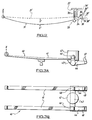
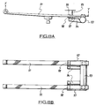
- A vehicle suspension comprising:suspension means including a pair of leaf springs (11) which extend longitudinally of an associated vehicle on respective opposed lateral sides thereof and each of which includes mounting means (X,Y) for attachment of the leaf spring (11) to the vehicle;an axle (12) attached to the leaf spring (11) intermediate the ends thereof; andanti-roll means (13) extending between and attached rigidly to each leaf spring (11) at a point spaced from the axle (12) and capable of rotational movement as a consequence of deflection of said suspension means during straight axle bounce motion,
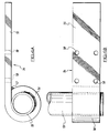
characterised by:counteracting means including at least one arm (14) which has one end attached rigidly to said anti-roll means (13) and its other end arranged to act upon the frame or chassis (17) of the vehicle, so that said counteracting means can act between said anti-roll means (13) and the vehicle frame or chassis (17),
whereby, when said suspension means deflects during straight axle bounce motion, said counteracting means acts to at least partially counteract the consequential rotational movement of said anti-roll means (13), thus applying a couple or moment to each leaf spring (11) and, as a result, altering the deflection and rate of each leaf spring (11) and, thus, altering the deflection and rate of the suspension. - A vehicle suspension according to claim 1, wherein said counteracting means includes a positive stop.
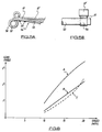
- A vehicle suspension according to claim 1, wherein said counteracting means is graduated to provide a gradually increasing resistance force against rotation of said anti-roll means (13).
- A vehicle suspension according to claim 3, wherein said graduated counteracting means terminates in a positive stop.
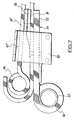
- A vehicle suspension according to any preceding claim, wherein said arm (54) of said counteracting means is arranged to act between said anti-roll means (53) and the vehicle frame or chassis (17) via another component of the suspension.
- A vehicle suspension according to claim 5, wherein the other suspension component is a leaf spring (61) connected to the vehicle frame or chassis (17).
- A vehicle suspension according to any of claims 1 to 4, wherein an end (15) of the arm (14) is arranged to act upon the vehicle frame or chassis (17) by means of spring means (16) arranged therebetween, to provide a gradually increasing force against rotation of said anti-roll means (13).
- A vehicle suspension according to claim 7, wherein said spring means (16) terminates in a positive stop.
- A vehicle suspension according to any preceding claim, wherein the arm (14) is resiliently flexible.
- A vehicle suspension according to any preceding claim, wherein said anti-roll means (53) and the arm (54) constitute a preformed unit associable with an existing vehicle suspension.
- A vehicle suspension according to any preceding claim, wherein said anti-roll means comprises an anti-roll bar or tube (13) arranged transversely of the vehicle frame or chassis (17) and having said counteracting means arranged generally centrally thereof.
- A vehicle suspension according to any preceding claim, wherein said anti-roll means comprises an anti-roll bar or tube (13) arranged transversely of the vehicle frame or chassis (17) and having said counteracting means arranged at each end thereof adjacent the respective leaf spring (11).
Applications Claiming Priority (3)
| Application Number | Priority Date | Filing Date | Title |
|---|---|---|---|
| GB91124610 | 1991-06-10 | ||
| GB919112461A GB9112461D0 (en) | 1991-06-10 | 1991-06-10 | Vehicle suspension |
| PCT/GB1992/001039 WO1992022438A1 (en) | 1991-06-10 | 1992-06-10 | Vehicle suspension |
Publications (2)
| Publication Number | Publication Date |
|---|---|
| EP0587663A1 EP0587663A1 (en) | 1994-03-23 |
| EP0587663B1 true EP0587663B1 (en) | 1998-04-22 |
Family
ID=10696402
Family Applications (1)
| Application Number | Title | Priority Date | Filing Date |
|---|---|---|---|
| EP92911436A Expired - Lifetime EP0587663B1 (en) | 1991-06-10 | 1992-06-10 | Vehicle suspension |
Country Status (8)
| Country | Link |
|---|---|
| US (1) | US5507516A (en) |
| EP (1) | EP0587663B1 (en) |
| AT (1) | ATE165286T1 (en) |
| AU (1) | AU1908792A (en) |
| DE (1) | DE69225225T2 (en) |
| ES (1) | ES2114939T3 (en) |
| GB (1) | GB9112461D0 (en) |
| WO (1) | WO1992022438A1 (en) |
Families Citing this family (12)
| Publication number | Priority date | Publication date | Assignee | Title |
|---|---|---|---|---|
| SE503443C2 (en) * | 1992-12-22 | 1996-06-17 | Volvo Ab | Leaf spring for suspension of a rigid wheel axle of a vehicle |
| US6015158A (en) * | 1998-06-24 | 2000-01-18 | Timbren Industries Inc. | Heavy duty truck suspension |
| US7048287B2 (en) * | 1999-06-10 | 2006-05-23 | Detroit Steel Products Co., Inc. | Air suspension anti-roll stabilization system |
| GB9913376D0 (en) * | 1999-06-10 | 1999-08-11 | Detroit Steel Products Co Inc | Air suspension anti-roll stabilisation system |
| GB2363594B (en) * | 2000-04-07 | 2003-09-17 | Harvey Bailey Eng Ltd | Vehicle wheel suspension |
| WO2002043976A1 (en) * | 2000-11-28 | 2002-06-06 | Detroit Steel Products Co., Inc. | Multi-leaf spring vehicle suspension with an anti-roll bar |
| US20060255556A1 (en) * | 2002-06-14 | 2006-11-16 | Reast John B | Leaf spring suspension systems and sub-assemblies therefor |
| GB0308572D0 (en) * | 2003-04-12 | 2003-05-21 | Detroit Steel Products Co Inc | Anti-roll leaf spring suspension |
| EP1526011B1 (en) * | 2003-10-24 | 2008-07-09 | Nissan Motor Company, Limited | Independent suspension system for a wheeled vehicle |
| US8342487B2 (en) * | 2004-01-19 | 2013-01-01 | Standens Ltd. | Anti-roll leaf spring suspension |
| GB0420887D0 (en) | 2004-09-20 | 2004-10-20 | Detroit Steel Products Co Inc | Vehicle suspension handling stabilsation system |
| US10618364B2 (en) * | 2017-01-09 | 2020-04-14 | Rassini Suspensiones, S.A. De C.V. | Hybrid leaf spring arrangement for vehicle suspension system |
Family Cites Families (17)
| Publication number | Priority date | Publication date | Assignee | Title |
|---|---|---|---|---|
| FR332159A (en) * | 1903-05-18 | 1903-10-17 | Thomas Georges Stevens | Mechanism advanced to produce simultaneous and uniform action of vehicle springs |
| DE266324C (en) * | 1912-08-19 | |||
| US1378665A (en) * | 1919-05-20 | 1921-05-17 | Ford Peter Du | Shock-absorber |
| BE496699A (en) * | 1947-08-04 | |||
| CH339508A (en) * | 1954-09-14 | 1959-06-30 | Leander Nilsson August | Suspension on vehicles |
| DE1012533B (en) * | 1955-06-11 | 1957-07-18 | E H Carl F W Borgward Dr Ing | Suspension for motor vehicles |
| GB954123A (en) * | 1962-03-06 | 1964-04-02 | Vauxhall Motors Ltd | Motor vehicle suspensions |
| FR1362660A (en) * | 1963-04-25 | 1964-06-05 | Citroen Sa Andre | Variable elasticity suspension |
| US3491994A (en) * | 1967-09-08 | 1970-01-27 | Ford Motor Co | Leaf spring vehicle suspension |
| FR2154297B1 (en) * | 1971-09-27 | 1975-02-21 | Citroen Sa | |
| US3860259A (en) * | 1973-12-03 | 1975-01-14 | Ford Motor Co | Rear suspension system for motor vehicle |
| US4094532A (en) * | 1977-05-16 | 1978-06-13 | Sway-A-Way Corporation | Torsion bar adjusting device |
| US4181324A (en) * | 1977-10-06 | 1980-01-01 | Hixon William K | Overload stabilizer unit for vehicle |
| FR2561997B1 (en) * | 1984-04-03 | 1988-10-14 | Aerospatiale | SUSPENSION SYSTEM FOR A RIGID AXLE VEHICLE WHEEL TRAIN |
| US5007660A (en) * | 1989-01-17 | 1991-04-16 | The B. F. Goodrich Company | Suspension system |
| GB8906600D0 (en) * | 1989-03-22 | 1989-05-04 | Detroit Steel Products Co Inc | Vehicle suspension |
| SE464398B (en) * | 1989-05-12 | 1991-04-22 | Zetterbergs Ind Ab | DEVICE ON TRUCKS |
-
1991
- 1991-06-10 GB GB919112461A patent/GB9112461D0/en active Pending
-
1992
- 1992-06-10 AT AT92911436T patent/ATE165286T1/en not_active IP Right Cessation
- 1992-06-10 DE DE69225225T patent/DE69225225T2/en not_active Expired - Fee Related
- 1992-06-10 WO PCT/GB1992/001039 patent/WO1992022438A1/en active IP Right Grant
- 1992-06-10 AU AU19087/92A patent/AU1908792A/en not_active Abandoned
- 1992-06-10 EP EP92911436A patent/EP0587663B1/en not_active Expired - Lifetime
- 1992-06-10 US US08/162,204 patent/US5507516A/en not_active Expired - Lifetime
- 1992-06-10 ES ES92911436T patent/ES2114939T3/en not_active Expired - Lifetime
Also Published As
| Publication number | Publication date |
|---|---|
| WO1992022438A1 (en) | 1992-12-23 |
| AU1908792A (en) | 1993-01-12 |
| GB9112461D0 (en) | 1991-07-31 |
| EP0587663A1 (en) | 1994-03-23 |
| ATE165286T1 (en) | 1998-05-15 |
| DE69225225T2 (en) | 1999-01-07 |
| DE69225225D1 (en) | 1998-05-28 |
| US5507516A (en) | 1996-04-16 |
| ES2114939T3 (en) | 1998-06-16 |
Similar Documents
| Publication | Publication Date | Title |
|---|---|---|
| JP3200435B2 (en) | Suspension system for vehicle wheel set | |
| US5924712A (en) | Dual trailing arm vehicle suspension | |
| CA2030027C (en) | Suspension with stiffener arm | |
| US6672605B2 (en) | Vehicle suspension systems | |
| EP1789268B1 (en) | Wheel suspension | |
| US6375203B1 (en) | Front air spring suspension with leading arm trailing and V-link | |
| US4781364A (en) | Elastic beam-torsion rod connection | |
| US6390485B1 (en) | Vehicle suspension | |
| US20090085318A1 (en) | Vehicle leaf spring suspension with radius arms | |
| EP0587663B1 (en) | Vehicle suspension | |
| US7798507B2 (en) | Vehicle suspension apparatus | |
| KR100433326B1 (en) | A zero roll suspension system | |
| US4632423A (en) | Structure for mounting stabilizer in vehicle suspension | |
| EP1185428B1 (en) | Air suspension anti-roll stabilisation system | |
| WO2006121438A2 (en) | Vehicle leaf spring suspension with radius arms | |
| EP1910108B1 (en) | Individual wheel suspension | |
| US7048287B2 (en) | Air suspension anti-roll stabilization system | |
| AU724085C (en) | Dual trailing arm vehicle suspension | |
| AU703820B2 (en) | Vehicle suspension | |
| JPH0653454B2 (en) | Suspension suspension stabilizer mounting structure for vehicles | |
| MXPA96003498A (en) | Vehic suspension | |
| KR20010059110A (en) | Semi-trailing arm type suspension system of vehicle |
Legal Events
| Date | Code | Title | Description |
|---|---|---|---|
| PUAI | Public reference made under article 153(3) epc to a published international application that has entered the european phase |
Free format text: ORIGINAL CODE: 0009012 |
|
| 17P | Request for examination filed |
Effective date: 19931112 |
|
| AK | Designated contracting states |
Kind code of ref document: A1 Designated state(s): AT BE CH DE DK ES FR GB GR IT LI LU MC NL SE |
|
| 17Q | First examination report despatched |
Effective date: 19950724 |
|
| APAB | Appeal dossier modified |
Free format text: ORIGINAL CODE: EPIDOS NOAPE |
|
| APBJ | Interlocutory revision of appeal recorded |
Free format text: ORIGINAL CODE: EPIDOS IRAPE |
|
| GRAG | Despatch of communication of intention to grant |
Free format text: ORIGINAL CODE: EPIDOS AGRA |
|
| GRAG | Despatch of communication of intention to grant |
Free format text: ORIGINAL CODE: EPIDOS AGRA |
|
| GRAH | Despatch of communication of intention to grant a patent |
Free format text: ORIGINAL CODE: EPIDOS IGRA |
|
| GRAH | Despatch of communication of intention to grant a patent |
Free format text: ORIGINAL CODE: EPIDOS IGRA |
|
| GRAA | (expected) grant |
Free format text: ORIGINAL CODE: 0009210 |
|
| ITF | It: translation for a ep patent filed |
Owner name: BARZANO' E ZANARDO ROMA S.P.A. |
|
| AK | Designated contracting states |
Kind code of ref document: B1 Designated state(s): AT BE CH DE DK ES FR GB GR IT LI LU MC NL SE |
|
| PG25 | Lapsed in a contracting state [announced via postgrant information from national office to epo] |
Ref country code: NL Free format text: LAPSE BECAUSE OF FAILURE TO SUBMIT A TRANSLATION OF THE DESCRIPTION OR TO PAY THE FEE WITHIN THE PRESCRIBED TIME-LIMIT Effective date: 19980422 Ref country code: LI Free format text: LAPSE BECAUSE OF FAILURE TO SUBMIT A TRANSLATION OF THE DESCRIPTION OR TO PAY THE FEE WITHIN THE PRESCRIBED TIME-LIMIT Effective date: 19980422 Ref country code: GR Free format text: LAPSE BECAUSE OF FAILURE TO SUBMIT A TRANSLATION OF THE DESCRIPTION OR TO PAY THE FEE WITHIN THE PRESCRIBED TIME-LIMIT Effective date: 19980422 Ref country code: CH Free format text: LAPSE BECAUSE OF FAILURE TO SUBMIT A TRANSLATION OF THE DESCRIPTION OR TO PAY THE FEE WITHIN THE PRESCRIBED TIME-LIMIT Effective date: 19980422 Ref country code: BE Free format text: LAPSE BECAUSE OF FAILURE TO SUBMIT A TRANSLATION OF THE DESCRIPTION OR TO PAY THE FEE WITHIN THE PRESCRIBED TIME-LIMIT Effective date: 19980422 Ref country code: AT Free format text: LAPSE BECAUSE OF FAILURE TO SUBMIT A TRANSLATION OF THE DESCRIPTION OR TO PAY THE FEE WITHIN THE PRESCRIBED TIME-LIMIT Effective date: 19980422 |
|
| REF | Corresponds to: |
Ref document number: 165286 Country of ref document: AT Date of ref document: 19980515 Kind code of ref document: T |
|
| REG | Reference to a national code |
Ref country code: CH Ref legal event code: EP |
|
| REF | Corresponds to: |
Ref document number: 69225225 Country of ref document: DE Date of ref document: 19980528 |
|
| PG25 | Lapsed in a contracting state [announced via postgrant information from national office to epo] |
Ref country code: LU Free format text: LAPSE BECAUSE OF NON-PAYMENT OF DUE FEES Effective date: 19980610 |
|
| REG | Reference to a national code |
Ref country code: ES Ref legal event code: FG2A Ref document number: 2114939 Country of ref document: ES Kind code of ref document: T3 |
|
| ET | Fr: translation filed | ||
| PG25 | Lapsed in a contracting state [announced via postgrant information from national office to epo] |
Ref country code: DK Free format text: LAPSE BECAUSE OF FAILURE TO SUBMIT A TRANSLATION OF THE DESCRIPTION OR TO PAY THE FEE WITHIN THE PRESCRIBED TIME-LIMIT Effective date: 19980722 |
|
| NLV1 | Nl: lapsed or annulled due to failure to fulfill the requirements of art. 29p and 29m of the patents act | ||
| REG | Reference to a national code |
Ref country code: CH Ref legal event code: PL |
|
| PG25 | Lapsed in a contracting state [announced via postgrant information from national office to epo] |
Ref country code: MC Free format text: LAPSE BECAUSE OF NON-PAYMENT OF DUE FEES Effective date: 19981231 |
|
| PLBE | No opposition filed within time limit |
Free format text: ORIGINAL CODE: 0009261 |
|
| STAA | Information on the status of an ep patent application or granted ep patent |
Free format text: STATUS: NO OPPOSITION FILED WITHIN TIME LIMIT |
|
| 26N | No opposition filed | ||
| EUG | Se: european patent has lapsed | ||
| REG | Reference to a national code |
Ref country code: GB Ref legal event code: IF02 |
|
| PGFP | Annual fee paid to national office [announced via postgrant information from national office to epo] |
Ref country code: ES Payment date: 20060530 Year of fee payment: 15 |
|
| PGFP | Annual fee paid to national office [announced via postgrant information from national office to epo] |
Ref country code: GB Payment date: 20060601 Year of fee payment: 15 |
|
| PGFP | Annual fee paid to national office [announced via postgrant information from national office to epo] |
Ref country code: SE Payment date: 20060607 Year of fee payment: 15 |
|
| PGFP | Annual fee paid to national office [announced via postgrant information from national office to epo] |
Ref country code: DE Payment date: 20060624 Year of fee payment: 15 |
|
| PGFP | Annual fee paid to national office [announced via postgrant information from national office to epo] |
Ref country code: FR Payment date: 20060627 Year of fee payment: 15 |
|
| PGFP | Annual fee paid to national office [announced via postgrant information from national office to epo] |
Ref country code: IT Payment date: 20060630 Year of fee payment: 15 |
|
| EUG | Se: european patent has lapsed | ||
| GBPC | Gb: european patent ceased through non-payment of renewal fee |
Effective date: 20070610 |
|
| REG | Reference to a national code |
Ref country code: FR Ref legal event code: ST Effective date: 20080229 |
|
| PG25 | Lapsed in a contracting state [announced via postgrant information from national office to epo] |
Ref country code: DE Free format text: LAPSE BECAUSE OF NON-PAYMENT OF DUE FEES Effective date: 20080101 |
|
| PG25 | Lapsed in a contracting state [announced via postgrant information from national office to epo] |
Ref country code: GB Free format text: LAPSE BECAUSE OF NON-PAYMENT OF DUE FEES Effective date: 20070610 |
|
| PG25 | Lapsed in a contracting state [announced via postgrant information from national office to epo] |
Ref country code: SE Free format text: LAPSE BECAUSE OF NON-PAYMENT OF DUE FEES Effective date: 20070611 |
|
| REG | Reference to a national code |
Ref country code: ES Ref legal event code: FD2A Effective date: 20070611 |
|
| PG25 | Lapsed in a contracting state [announced via postgrant information from national office to epo] |
Ref country code: FR Free format text: LAPSE BECAUSE OF NON-PAYMENT OF DUE FEES Effective date: 20070702 |
|
| PG25 | Lapsed in a contracting state [announced via postgrant information from national office to epo] |
Ref country code: ES Free format text: LAPSE BECAUSE OF NON-PAYMENT OF DUE FEES Effective date: 20070611 |
|
| PG25 | Lapsed in a contracting state [announced via postgrant information from national office to epo] |
Ref country code: IT Free format text: LAPSE BECAUSE OF NON-PAYMENT OF DUE FEES Effective date: 20070610 |