EP0586840A1 - Fastening device for adjustably fastening a panel to a frame member and a resulting wall element - Google Patents
Fastening device for adjustably fastening a panel to a frame member and a resulting wall element Download PDFInfo
- Publication number
- EP0586840A1 EP0586840A1 EP93111504A EP93111504A EP0586840A1 EP 0586840 A1 EP0586840 A1 EP 0586840A1 EP 93111504 A EP93111504 A EP 93111504A EP 93111504 A EP93111504 A EP 93111504A EP 0586840 A1 EP0586840 A1 EP 0586840A1
- Authority
- EP
- European Patent Office
- Prior art keywords
- fastening
- holding part
- fastening element
- contact surface
- anchor
- Prior art date
- Legal status (The legal status is an assumption and is not a legal conclusion. Google has not performed a legal analysis and makes no representation as to the accuracy of the status listed.)
- Granted
Links
Images
Classifications
-
- E—FIXED CONSTRUCTIONS
- E06—DOORS, WINDOWS, SHUTTERS, OR ROLLER BLINDS IN GENERAL; LADDERS
- E06B—FIXED OR MOVABLE CLOSURES FOR OPENINGS IN BUILDINGS, VEHICLES, FENCES OR LIKE ENCLOSURES IN GENERAL, e.g. DOORS, WINDOWS, BLINDS, GATES
- E06B3/00—Window sashes, door leaves, or like elements for closing wall or like openings; Layout of fixed or moving closures, e.g. windows in wall or like openings; Features of rigidly-mounted outer frames relating to the mounting of wing frames
- E06B3/02—Wings made completely of glass
-
- A—HUMAN NECESSITIES
- A47—FURNITURE; DOMESTIC ARTICLES OR APPLIANCES; COFFEE MILLS; SPICE MILLS; SUCTION CLEANERS IN GENERAL
- A47K—SANITARY EQUIPMENT NOT OTHERWISE PROVIDED FOR; TOILET ACCESSORIES
- A47K3/00—Baths; Douches; Appurtenances therefor
- A47K3/28—Showers or bathing douches
- A47K3/30—Screens or collapsible cabinets for showers or baths
-
- E—FIXED CONSTRUCTIONS
- E05—LOCKS; KEYS; WINDOW OR DOOR FITTINGS; SAFES
- E05D—HINGES OR SUSPENSION DEVICES FOR DOORS, WINDOWS OR WINGS
- E05D15/00—Suspension arrangements for wings
- E05D15/06—Suspension arrangements for wings for wings sliding horizontally more or less in their own plane
- E05D15/0621—Details, e.g. suspension or supporting guides
- E05D15/0626—Details, e.g. suspension or supporting guides for wings suspended at the top
- E05D15/0647—Details, e.g. suspension or supporting guides for wings suspended at the top on sliding blocks
-
- A—HUMAN NECESSITIES
- A47—FURNITURE; DOMESTIC ARTICLES OR APPLIANCES; COFFEE MILLS; SPICE MILLS; SUCTION CLEANERS IN GENERAL
- A47K—SANITARY EQUIPMENT NOT OTHERWISE PROVIDED FOR; TOILET ACCESSORIES
- A47K3/00—Baths; Douches; Appurtenances therefor
- A47K3/28—Showers or bathing douches
- A47K3/30—Screens or collapsible cabinets for showers or baths
- A47K2003/307—Adjustable connections to the wall
-
- E—FIXED CONSTRUCTIONS
- E05—LOCKS; KEYS; WINDOW OR DOOR FITTINGS; SAFES
- E05Y—INDEXING SCHEME RELATING TO HINGES OR OTHER SUSPENSION DEVICES FOR DOORS, WINDOWS OR WINGS AND DEVICES FOR MOVING WINGS INTO OPEN OR CLOSED POSITION, CHECKS FOR WINGS AND WING FITTINGS NOT OTHERWISE PROVIDED FOR, CONCERNED WITH THE FUNCTIONING OF THE WING
- E05Y2201/00—Constructional elements; Accessories therefore
- E05Y2201/60—Suspension or transmission members; Accessories therefore
- E05Y2201/622—Suspension or transmission members elements
- E05Y2201/706—Shafts
-
- E—FIXED CONSTRUCTIONS
- E05—LOCKS; KEYS; WINDOW OR DOOR FITTINGS; SAFES
- E05Y—INDEXING SCHEME RELATING TO HINGES OR OTHER SUSPENSION DEVICES FOR DOORS, WINDOWS OR WINGS AND DEVICES FOR MOVING WINGS INTO OPEN OR CLOSED POSITION, CHECKS FOR WINGS AND WING FITTINGS NOT OTHERWISE PROVIDED FOR, CONCERNED WITH THE FUNCTIONING OF THE WING
- E05Y2600/00—Mounting or coupling arrangements for elements provided for in this subclass
- E05Y2600/10—Adjustable or movable
- E05Y2600/30—Adjustable or movable characterised by the type of motion
- E05Y2600/33—Stepwise motion
-
- E—FIXED CONSTRUCTIONS
- E05—LOCKS; KEYS; WINDOW OR DOOR FITTINGS; SAFES
- E05Y—INDEXING SCHEME RELATING TO HINGES OR OTHER SUSPENSION DEVICES FOR DOORS, WINDOWS OR WINGS AND DEVICES FOR MOVING WINGS INTO OPEN OR CLOSED POSITION, CHECKS FOR WINGS AND WING FITTINGS NOT OTHERWISE PROVIDED FOR, CONCERNED WITH THE FUNCTIONING OF THE WING
- E05Y2600/00—Mounting or coupling arrangements for elements provided for in this subclass
- E05Y2600/60—Mounting or coupling members; Accessories therefore
- E05Y2600/622—Dowels; Pins
-
- E—FIXED CONSTRUCTIONS
- E05—LOCKS; KEYS; WINDOW OR DOOR FITTINGS; SAFES
- E05Y—INDEXING SCHEME RELATING TO HINGES OR OTHER SUSPENSION DEVICES FOR DOORS, WINDOWS OR WINGS AND DEVICES FOR MOVING WINGS INTO OPEN OR CLOSED POSITION, CHECKS FOR WINGS AND WING FITTINGS NOT OTHERWISE PROVIDED FOR, CONCERNED WITH THE FUNCTIONING OF THE WING
- E05Y2800/00—Details, accessories and auxiliary operations not otherwise provided for
- E05Y2800/67—Materials; Strength alteration thereof
- E05Y2800/672—Glass
-
- E—FIXED CONSTRUCTIONS
- E05—LOCKS; KEYS; WINDOW OR DOOR FITTINGS; SAFES
- E05Y—INDEXING SCHEME RELATING TO HINGES OR OTHER SUSPENSION DEVICES FOR DOORS, WINDOWS OR WINGS AND DEVICES FOR MOVING WINGS INTO OPEN OR CLOSED POSITION, CHECKS FOR WINGS AND WING FITTINGS NOT OTHERWISE PROVIDED FOR, CONCERNED WITH THE FUNCTIONING OF THE WING
- E05Y2900/00—Application of doors, windows, wings or fittings thereof
- E05Y2900/10—Application of doors, windows, wings or fittings thereof for buildings or parts thereof
- E05Y2900/114—Application of doors, windows, wings or fittings thereof for buildings or parts thereof for showers
-
- Y—GENERAL TAGGING OF NEW TECHNOLOGICAL DEVELOPMENTS; GENERAL TAGGING OF CROSS-SECTIONAL TECHNOLOGIES SPANNING OVER SEVERAL SECTIONS OF THE IPC; TECHNICAL SUBJECTS COVERED BY FORMER USPC CROSS-REFERENCE ART COLLECTIONS [XRACs] AND DIGESTS
- Y10—TECHNICAL SUBJECTS COVERED BY FORMER USPC
- Y10T—TECHNICAL SUBJECTS COVERED BY FORMER US CLASSIFICATION
- Y10T403/00—Joints and connections
- Y10T403/71—Rod side to plate or side
- Y10T403/7117—Flanged or grooved rod
-
- Y—GENERAL TAGGING OF NEW TECHNOLOGICAL DEVELOPMENTS; GENERAL TAGGING OF CROSS-SECTIONAL TECHNOLOGIES SPANNING OVER SEVERAL SECTIONS OF THE IPC; TECHNICAL SUBJECTS COVERED BY FORMER USPC CROSS-REFERENCE ART COLLECTIONS [XRACs] AND DIGESTS
- Y10—TECHNICAL SUBJECTS COVERED BY FORMER USPC
- Y10T—TECHNICAL SUBJECTS COVERED BY FORMER US CLASSIFICATION
- Y10T403/00—Joints and connections
- Y10T403/76—Joints and connections having a cam, wedge, or tapered portion
Definitions
- the invention relates to a fastening element according to the preamble of claim 1 and a wall element according to the preamble of claim 10 and claim 12.
- Such fastening and wall elements are used, for example, in shop fronts and in furniture construction.
- the object of the invention is to provide a possibility for fastening the plates to a frame element, which allows the position of the plate to be adjusted relative to the frame element.
- the invention allows plates to be fastened to the frame element and, if the position of the plate does not meet the requirements, to loosen the connection again, to adjust the fastening element and to close the plate again fasten.
- the position of the plate can be corrected both with regard to the distance of the opposite edge from the frame element and with respect to the angular position of the plate to the frame element.
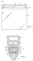
- a wall element is shown - it can be a fixed element, but also a sliding element or a door - with an upper frame 1, an aluminum profile to which a glass plate 2 is attached.
- the connection between the frame bar 1 and the glass plate 2 is anchored to the same by two near the ends of the frame bar 1
- Fastening elements 3 made of plastic, which protrude through circular holes 4 in the glass plate 2.
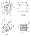
- Each fastening element 3 consists (FIGS. 2, 3a, b, 4) of an anchor part 5 and a holding part 6 which is plugged onto it and which surrounds the anchor part 5 like a ring and has a contact surface 7 on the outside. It fits exactly into the hole 4 so that its edge is continuously touched by the contact surface 7.
- the anchor part 5 engages with anchor pins 8 in anchor grooves 10 arranged laterally in a receiving groove 9 of the frame strip 1.
- the anchor pins 8 are delimited on the top and bottom by two parallel sliding surfaces 11a, b which are in contact with the side surfaces of the anchor grooves 10.
- the anchor part 5 has essentially the shape of a cylinder, the axis of which forms an adjusting axis 12, as explained in more detail below. However, it has teeth with axially extending teeth on its outer surface 13. Adjacent teeth are offset by an increment ⁇ of 10 °.
- the holding part 6 has an inner surface 14 with complementary teeth. Its outer surface, the contact surface 7, is an eccentric cylinder jacket surface to the inner surface 14 of the holding part 6, the axis of which is an eccentric axis 15 parallel to the adjustment axis 12 and spaced from it by an eccentricity ⁇ .
- the holding part 6 can be pulled off the anchor part 5, rotated to the right by any multiple of the increment ⁇ , in the extreme case, which is shown below, for example, by 90 ° and plugged back onto the anchor part 5.
- the holding part 6 is then rotated 90 ° to the right with respect to the adjustment axis 12 (see FIG. 5) and the contact surface 7 is, based on the armature part 5, by the eccentricity ⁇ , the distance between the adjustment axis 12 and the eccentric axis 15 , higher than before. If turned to the left, it would be correspondingly lower.
- the holding part 6 can take 36 different angular positions with respect to the adjustment axis 12, which are as many different, i.e. H.
- the fastening part 3 can now be inserted again into the hole 4 in the glass plate 2 and the same can be pushed to the left again, the anchor pins 8 in turn engaging in the anchor grooves 10, so that the vertical position of the anchor part 5 with respect to the frame strip 1 is unchanged while the same is horizontally shifted to the left by the eccentricity ⁇ , but this has no effect on the position of the glass plate 2.
- the contact surface 7 of the holding part 6 is raised relative to the frame bar 1 by the eccentricity ⁇ and thus also the hole 4 in the glass plate 2 and thus the right side thereof, so that the falling off of the lower edge is corrected.
- the glass plate 2 can now be definitely fixed in the frame by wedging and cementing.
Abstract
Description
Die Erfindung betrifft ein Befestigungselement gemäss dem Oberbegriff des Anspruchs 1 sowie ein Wandelement gemäss dem Oberbegriff des Anspruchs 10 und des Anspruchs 12. Derartige Befestigungs- und Wandelemente kommen etwa bei Geschäftsfronten und im Möbelbau zum Einsatz.The invention relates to a fastening element according to the preamble of
Bei der Befestigung von Platten, insbesondere Glasplatten an Rahmenleisten, welche z. B. als Metallprofile ausgebildet sein können, treten immer wieder Schwierigkeiten auf, weil die Platten ungenau geschnitten sind. Werden sie einfach in eine Aufnahmenut etwa einer oberen Rahmenleiste bis zum Anschlag eingeführt und dann verkittet, so passen oft die Seitenränder benachbarter Platten nicht aneinander oder es ergeben sich Schwierigkeiten mit der Einpassung in eine untere Rahmenleiste.When attaching plates, especially glass plates on frame strips, which, for. B. can be designed as metal profiles, difficulties arise again and again because the plates are cut imprecisely. If they are simply inserted as far as possible into a receiving groove in an upper frame ledge and then cemented, the side edges of adjacent panels often do not match or there are difficulties with fitting into a lower frame ledge.
Aufgabe der Erfindung ist es, eine Möglichkeit zur Befestigung der Platten an einem Rahmenelement zu schaffen, welche es erlaubt, die Lage der Platte relativ zum Rahmenelement zu justieren.The object of the invention is to provide a possibility for fastening the plates to a frame element, which allows the position of the plate to be adjusted relative to the frame element.
Diese Aufgabe wird durch die Erfindung, wie sie in den Ansprüchen gekennzeichnet ist, gelöst. Die Erfindung erlaubt es, Platten am Rahmenelement zu befestigen und, falls die Lage der Platte nicht den Erfordernissen entspricht, die Verbindung wieder zu lösen, das Befestigungselement zu justieren und die Platte wieder zu befestigen. Die Lage der Platte kann dabei sowohl bezüglich des Abstands des gegenüberliegenden Randes vom Rahmenelement als auch bezüglich der Winkellage der Platte zum Rahmenelement korrigiert werden.This object is achieved by the invention as characterized in the claims. The invention allows plates to be fastened to the frame element and, if the position of the plate does not meet the requirements, to loosen the connection again, to adjust the fastening element and to close the plate again fasten. The position of the plate can be corrected both with regard to the distance of the opposite edge from the frame element and with respect to the angular position of the plate to the frame element.
In folgenden wird die Erfindung anhand von Zeichnungen, welche nur ein Ausführungsbeispiel darstellen, näher erläutert. Es zeigen
- Fig. 1
- eine Frontansicht eines erfindungsgemässen Wandelements mit zwei erfindungsgemässen Befestigungselementen,
- Fig. 2
- vergrössert einen Schnitt längs II-II in Fig. 1,
- Fig. 3a
- eine Seitenansicht eines erfindungsgemässen Befestigungselements,
- Fig. 3b
- eine weitere Seitenansicht des Befestigungselements aus der Richtung des Pfeils B in Fig. 3a,
- Fig. 4
- eine Draufsicht auf einen Teil des Befestigungselements nach den Fig. 3a,b und
- Fig. 5
- eine Seitenansicht des Befestigungselements entsprechend Fig. 3a bei anderer Justierung desselben.
- Fig. 1
- 2 shows a front view of a wall element according to the invention with two fastening elements according to the invention,
- Fig. 2
- enlarges a section along II-II in Fig. 1,
- Fig. 3a
- a side view of a fastening element according to the invention,
- Fig. 3b
- 3 shows a further side view of the fastening element from the direction of arrow B in FIG. 3a,
- Fig. 4
- a plan view of a part of the fastener according to FIGS. 3a, b and
- Fig. 5
- a side view of the fastener corresponding to Fig. 3a with the same adjustment.
In Fig. 1 ist ein Wandelement dargestellt - es kann sich dabei um ein festmontiertes Element, aber auch um ein Schiebeelement oder eine Türe handeln - mit einer oberen Rahmenleiste 1, einem Aluminiumprofil, an welcher eine Glasplatte 2 befestigt ist. Die Verbindung zwischen der Rahmenleiste 1 und der Glasplatte 2 ist durch zwei in der Nähe der Enden der Rahmenleiste 1 an derselben verankerte Befestigungselemente 3 aus Kunststoff hergestellt, welche durch kreisrunde Löcher 4 in der Glasplatte 2 ragen.In Fig. 1, a wall element is shown - it can be a fixed element, but also a sliding element or a door - with an
Jedes Befestigungselement 3 besteht (Fig. 2, 3a,b, 4) aus einem Ankerteil 5 und einem auf dasselbe aufgesteckten Halteteil 6, welches das Ankerteil 5 ringartig umgibt und aussen eine Kontaktfläche 7 aufweist. Es passt genau in das Loch 4, sodass dessen Rand durchgehend von der Kontaktfläche 7 berührt wird. Das Ankerteil 5 greift mit Ankerzapfen 8 in seitlich in einer Aufnahmenut 9 der Rahmenleiste 1 angebrachte Ankernuten 10. Die Ankerzapfen 8 sind an der Ober- und Unterseite von zwei parallelen Gleitflächen 11a,b begrenzt, welche mit den Seitenflächen der Ankernuten 10 in Kontakt stehen.Each
Das Ankerteil 5 hat, von den axial abstehenden Ankerzapfen 8 abgesehen, im wesentlichen die Form eines Zylinders, dessen Achse eine Justierachse 12 bildet, wie unten näher ausgeführt. Es weist allerdings an seiner Mantelfläche 13 eine Verzahnung mit axial verlaufenden Zähnen auf. Benachbarte Zähne sind um ein Inkrement α von 10° versetzt. Das Halteteil 6 weist eine Innenfläche 14 mit komplementärer Verzahnung auf. Seine Aussenfläche, die Kontaktfläche 7, ist eine zur Innenfläche 14 des Halteteils 6 exzentrische Zylindermantelfläche, deren Achse eine zur Justierachse 12 parallele, von ihr um eine Exzentrizität Δ beabstandete Exzenterachse 15 ist.Apart from the axially projecting
Falls nun die Glasplatte 2 nicht genau geschnitten ist und z. B. nach rechts (Fig. 1) hin breiter wird, so verläuft, wenn beide Befestigungselemente 3 wie in Fig. 3a,b dargestellt eingestellt sind, ihre Unterkante nicht parallel zur Rahmenleiste 1, sondern fällt nach rechts ab. Zur Korrektur kann nun die Glasplatte 2 nach rechts verschoben werden, bis das rechte der Befestigungselemente 3 zugänglich ist und aus dem Loch 4 herausgenommen werden kann.If the
Anschliessend kann das Halteteil 6 vom Ankerteil 5 abgezogen, um ein beliebiges Vielfaches des Inkrements α nach rechts gedreht werden, im Extremfall, der im folgenden beispielsweise dargestellt wird, um 90°, und wieder auf das Ankerteil 5 aufgesteckt werden. Das Halteteil 6 ist dann also bezüglich der Justierachse 12 um 90° nach rechts verdreht (s. Fig. 5) und die Kontaktfläche 7 liegt, bezogen auf das Ankerteil 5, um die Exzentrizität Δ, die Distanz zwischen der Justierachse 12 und der Exzenterachse 15, höher als zuvor. Bei Linksdrehung läge sie entsprechend tiefer. Insgesamt kann das Halteteil 6 36 verschiedene Winkelpositionen bezüglich der Justierachse 12 einnehmen, denen ebensoviele verschiedene, d. h. gegeneinander verschobene Lagen der Kontaktfläche 7 bezüglich der Justierachse 12 entsprechen, die zu 19 verschiedenen vertikalen Positionen der Kontaktfläche 7 führen. Da dieselbe um die zur Justierachse 12 parallele Exzenterachse 15 rotationssymmetrisch ist, wird durch die Drehung des Halteteils 6 nur ihre Lage, aber nicht ihre Form verändert.Subsequently, the
Das Befestigungsteil 3 kann nun wieder in das Loch 4 in der Glasplatte 2 eingesteckt und dieselbe wieder nach links geschoben werden, wobei die Ankerzapfen 8 wiederum in die Ankernuten 10 eingreifen, sodass die vertikale Position des Ankerteils 5 bezüglich der Rahmenleiste 1 unverändert ist, während dasselbe horizontal um die Exzentrizität Δ nach links verschoben ist, was sich jedoch auf die Position der Glasplatte 2 nicht auswirkt. Dagegen ist die Kontaktfläche 7 des Halteteils 6 gegenüber der Rahmenleiste 1 um die Exzentrizität Δ angehoben und damit auch das Loch 4 in der Glasplatte 2 und damit die rechte Seite derselben, sodass das Abfallen der Unterkante korrigiert ist. Die Glasplatte 2 kann nun durch Verkeilen und Verkitten definitiv in der Rahmenleiste fixiert werden.The
Claims (13)
Applications Claiming Priority (2)
| Application Number | Priority Date | Filing Date | Title |
|---|---|---|---|
| CH2850/92 | 1992-09-09 | ||
| CH285092 | 1992-09-09 |
Publications (2)
| Publication Number | Publication Date |
|---|---|
| EP0586840A1 true EP0586840A1 (en) | 1994-03-16 |
| EP0586840B1 EP0586840B1 (en) | 1996-10-09 |
Family
ID=4242986
Family Applications (1)
| Application Number | Title | Priority Date | Filing Date |
|---|---|---|---|
| EP93111504A Expired - Lifetime EP0586840B1 (en) | 1992-09-09 | 1993-07-17 | Fastening device for adjustably fastening a panel to a frame member and a resulting wall element |
Country Status (8)
| Country | Link |
|---|---|
| US (1) | US5449243A (en) |
| EP (1) | EP0586840B1 (en) |
| AT (1) | ATE144022T1 (en) |
| AU (1) | AU664300B2 (en) |
| CA (1) | CA2103535C (en) |
| DE (1) | DE59304108D1 (en) |
| ES (1) | ES2092732T3 (en) |
| MX (1) | MX9305332A (en) |
Cited By (3)
| Publication number | Priority date | Publication date | Assignee | Title |
|---|---|---|---|---|
| EP1359279A1 (en) | 2002-04-23 | 2003-11-05 | Hawa Ag | Device for supporting plates and partition element |
| US7748178B2 (en) | 2006-10-23 | 2010-07-06 | Hawa Ag | Device for holding panels and separation element |
| US7891052B2 (en) | 2006-10-19 | 2011-02-22 | Hawa Ag | Device with a carriage for holding panels and a separation element |
Families Citing this family (5)
| Publication number | Priority date | Publication date | Assignee | Title |
|---|---|---|---|---|
| US5927665A (en) * | 1998-07-02 | 1999-07-27 | Allied Construction Products, Inc. | Implement mounting system |
| DE10360589A1 (en) | 2003-12-19 | 2005-07-14 | Geze Gmbh | One-piece support clamping profile without glass bore for MSW |
| DE102007021731A1 (en) * | 2007-05-09 | 2008-11-13 | BSH Bosch und Siemens Hausgeräte GmbH | Fastening device for fastening objects to a base |
| US11834878B2 (en) * | 2018-03-09 | 2023-12-05 | Austin Hardware & Supply, Inc. | Sliding closure for cabinets |
| CN113007500B (en) * | 2021-02-10 | 2022-04-05 | 中国商用飞机有限责任公司 | Foot margin fixing device |
Citations (6)
| Publication number | Priority date | Publication date | Assignee | Title |
|---|---|---|---|---|
| US4106876A (en) * | 1975-12-20 | 1978-08-15 | Westinghouse Brake And Signal Company Limited | Door mountings |
| GB2045847A (en) * | 1979-02-26 | 1980-11-05 | Guenter & Co Oni Metall | Adjustable roller carriers for a sliding door |
| GB2098853A (en) * | 1981-05-21 | 1982-12-01 | Ford Motor Co | Motor vehicle with vertically adjustable safety-belt guide fitting |
| DE3308812A1 (en) * | 1983-03-12 | 1984-09-13 | Hüppe GmbH, 2900 Oldenburg | Supporting and running roller device for sliding doors |
| EP0171695A1 (en) * | 1984-08-07 | 1986-02-19 | Heinz Georg Baus | Shower screen |
| GB2182085A (en) * | 1985-10-26 | 1987-05-07 | Foldor Limited | Sliding door |
Family Cites Families (6)
| Publication number | Priority date | Publication date | Assignee | Title |
|---|---|---|---|---|
| FR837315A (en) * | 1937-10-22 | 1939-02-08 | Coindet Ets | New way of assembling panels for doors, partitions, etc., made of double-walled metal |
| US3703053A (en) * | 1971-09-17 | 1972-11-21 | Gen Motors Corp | Vehicle window installation |
| US4050200A (en) * | 1976-12-27 | 1977-09-27 | The Stolle Corporation | Removable hatch structure for automobiles |
| DE3727153A1 (en) * | 1987-08-14 | 1989-02-23 | Kuester & Co Gmbh | BOWDENSE WINDOW REGULATOR |
| DE3801909A1 (en) * | 1988-01-23 | 1989-08-03 | Netter Gmbh | MACHINE ELEMENT FASTENING |
| US5141357A (en) * | 1991-01-09 | 1992-08-25 | Sundstrand Corp. | Misalignment compensating fastener insert |
-
1993
- 1993-07-17 ES ES93111504T patent/ES2092732T3/en not_active Expired - Lifetime
- 1993-07-17 EP EP93111504A patent/EP0586840B1/en not_active Expired - Lifetime
- 1993-07-17 DE DE59304108T patent/DE59304108D1/en not_active Expired - Lifetime
- 1993-07-17 AT AT93111504T patent/ATE144022T1/en active
- 1993-08-04 AU AU44423/93A patent/AU664300B2/en not_active Ceased
- 1993-08-06 CA CA002103535A patent/CA2103535C/en not_active Expired - Lifetime
- 1993-09-01 US US08/115,385 patent/US5449243A/en not_active Expired - Lifetime
- 1993-09-01 MX MX9305332A patent/MX9305332A/en unknown
Patent Citations (6)
| Publication number | Priority date | Publication date | Assignee | Title |
|---|---|---|---|---|
| US4106876A (en) * | 1975-12-20 | 1978-08-15 | Westinghouse Brake And Signal Company Limited | Door mountings |
| GB2045847A (en) * | 1979-02-26 | 1980-11-05 | Guenter & Co Oni Metall | Adjustable roller carriers for a sliding door |
| GB2098853A (en) * | 1981-05-21 | 1982-12-01 | Ford Motor Co | Motor vehicle with vertically adjustable safety-belt guide fitting |
| DE3308812A1 (en) * | 1983-03-12 | 1984-09-13 | Hüppe GmbH, 2900 Oldenburg | Supporting and running roller device for sliding doors |
| EP0171695A1 (en) * | 1984-08-07 | 1986-02-19 | Heinz Georg Baus | Shower screen |
| GB2182085A (en) * | 1985-10-26 | 1987-05-07 | Foldor Limited | Sliding door |
Cited By (4)
| Publication number | Priority date | Publication date | Assignee | Title |
|---|---|---|---|---|
| EP1359279A1 (en) | 2002-04-23 | 2003-11-05 | Hawa Ag | Device for supporting plates and partition element |
| US7891052B2 (en) | 2006-10-19 | 2011-02-22 | Hawa Ag | Device with a carriage for holding panels and a separation element |
| US7748178B2 (en) | 2006-10-23 | 2010-07-06 | Hawa Ag | Device for holding panels and separation element |
| EP1916372A3 (en) * | 2006-10-23 | 2013-05-15 | Hawa Ag | Holding device for panels and separating element |
Also Published As
| Publication number | Publication date |
|---|---|
| DE59304108D1 (en) | 1996-11-14 |
| AU664300B2 (en) | 1995-11-09 |
| AU4442393A (en) | 1994-03-17 |
| CA2103535C (en) | 2003-10-07 |
| US5449243A (en) | 1995-09-12 |
| ES2092732T3 (en) | 1996-12-01 |
| CA2103535A1 (en) | 1994-03-10 |
| ATE144022T1 (en) | 1996-10-15 |
| MX9305332A (en) | 1994-06-30 |
| EP0586840B1 (en) | 1996-10-09 |
Similar Documents
| Publication | Publication Date | Title |
|---|---|---|
| DE60033343T2 (en) | Mounting frame for liquid crystal display modules | |
| EP2531065B1 (en) | Drawer structure | |
| DE2911094A1 (en) | PANEL CONNECTION SYSTEM | |
| EP0645957B1 (en) | Cabinet frame | |
| EP0296459A1 (en) | Frame for a textile machine, particularly for a spinning or twisting machine | |
| EP0586840B1 (en) | Fastening device for adjustably fastening a panel to a frame member and a resulting wall element | |
| DE3708574A1 (en) | FITTING SYSTEM FOR FASTENING OR STORAGE OF FRAMELESS GLASS PANELS | |
| DE2611323A1 (en) | ADJUSTMENT DEVICE | |
| DE602004005534T2 (en) | Elastic fastening element with an anti-twist device | |
| DE10230181A1 (en) | Modular lighting elements and lighting strips composed of them | |
| DE1934581A1 (en) | Furniture hinge | |
| DE4233402C2 (en) | Fastening device for rails with rows of openings and holes | |
| EP0455973A1 (en) | Guide rail for elevator door | |
| EP3973818A1 (en) | Drawer side wall | |
| DE2638585C2 (en) | Rectangular base or adjustment plate | |
| DE102014101284B3 (en) | Frame arrangement and mounting plate | |
| EP1582802A1 (en) | Fixture for a flat screen | |
| DE202023101806U1 (en) | panel mount | |
| DE102012109589B4 (en) | furniture | |
| AT404960B (en) | DISTANCE ELEMENT FOR FASTENING A HINGE | |
| EP0602378A1 (en) | Device for fitting fume-extraction hoods into or between hanging cabinet elements | |
| DE60021648T2 (en) | Carrier for curtain rail | |
| DE2232728A1 (en) | HINGE FOR FURNITURE DOORS | |
| DE3150630A1 (en) | Supporting bracket | |
| DE60112587T2 (en) | Fastening device for panels in a partition wall system |
Legal Events
| Date | Code | Title | Description |
|---|---|---|---|
| PUAI | Public reference made under article 153(3) epc to a published international application that has entered the european phase |
Free format text: ORIGINAL CODE: 0009012 |
|
| AK | Designated contracting states |
Kind code of ref document: A1 Designated state(s): AT CH DE ES FR IT LI NL |
|
| 17P | Request for examination filed |
Effective date: 19940402 |
|
| 17Q | First examination report despatched |
Effective date: 19950403 |
|
| GRAH | Despatch of communication of intention to grant a patent |
Free format text: ORIGINAL CODE: EPIDOS IGRA |
|
| GRAH | Despatch of communication of intention to grant a patent |
Free format text: ORIGINAL CODE: EPIDOS IGRA |
|
| RAP1 | Party data changed (applicant data changed or rights of an application transferred) |
Owner name: HAAB, OTTO Owner name: HAAB, KARL |
|
| GRAA | (expected) grant |
Free format text: ORIGINAL CODE: 0009210 |
|
| AK | Designated contracting states |
Kind code of ref document: B1 Designated state(s): AT CH DE ES FR IT LI NL |
|
| REF | Corresponds to: |
Ref document number: 144022 Country of ref document: AT Date of ref document: 19961015 Kind code of ref document: T |
|
| REG | Reference to a national code |
Ref country code: CH Ref legal event code: NV Representative=s name: ZIMMERLI, WAGNER & PARTNER AG |
|
| REF | Corresponds to: |
Ref document number: 59304108 Country of ref document: DE Date of ref document: 19961114 |
|
| ET | Fr: translation filed | ||
| ITF | It: translation for a ep patent filed |
Owner name: SAIC BREVETTI S.R.L. |
|
| REG | Reference to a national code |
Ref country code: ES Ref legal event code: FG2A Ref document number: 2092732 Country of ref document: ES Kind code of ref document: T3 |
|
| PLBE | No opposition filed within time limit |
Free format text: ORIGINAL CODE: 0009261 |
|
| STAA | Information on the status of an ep patent application or granted ep patent |
Free format text: STATUS: NO OPPOSITION FILED WITHIN TIME LIMIT |
|
| 26N | No opposition filed | ||
| REG | Reference to a national code |
Ref country code: CH Ref legal event code: PFA Owner name: HAAB, KARL Free format text: HAAB, KARL#OBERE WEIDSTRASSE 7#CH-6343 ROTKREUZ (CH) $ HAAB, OTTO#ZUERICHSTRASSE 25#CH-8932 METTMENSTETTEN (CH) -TRANSFER TO- HAAB, KARL#OBERE WEIDSTRASSE 7#CH-6343 ROTKREUZ (CH) $ HAAB, OTTO#ZUERICHSTRASSE 25#CH-8932 METTMENSTETTEN (CH) |
|
| PGFP | Annual fee paid to national office [announced via postgrant information from national office to epo] |
Ref country code: FR Payment date: 20110727 Year of fee payment: 19 Ref country code: CH Payment date: 20110718 Year of fee payment: 19 |
|
| PGFP | Annual fee paid to national office [announced via postgrant information from national office to epo] |
Ref country code: ES Payment date: 20110817 Year of fee payment: 19 Ref country code: DE Payment date: 20110713 Year of fee payment: 19 Ref country code: AT Payment date: 20110628 Year of fee payment: 19 |
|
| PGFP | Annual fee paid to national office [announced via postgrant information from national office to epo] |
Ref country code: IT Payment date: 20110714 Year of fee payment: 19 Ref country code: NL Payment date: 20110715 Year of fee payment: 19 |
|
| REG | Reference to a national code |
Ref country code: NL Ref legal event code: V1 Effective date: 20130201 |
|
| REG | Reference to a national code |
Ref country code: CH Ref legal event code: PL |
|
| REG | Reference to a national code |
Ref country code: AT Ref legal event code: MM01 Ref document number: 144022 Country of ref document: AT Kind code of ref document: T Effective date: 20120717 |
|
| REG | Reference to a national code |
Ref country code: FR Ref legal event code: ST Effective date: 20130329 |
|
| PG25 | Lapsed in a contracting state [announced via postgrant information from national office to epo] |
Ref country code: CH Free format text: LAPSE BECAUSE OF NON-PAYMENT OF DUE FEES Effective date: 20120731 Ref country code: DE Free format text: LAPSE BECAUSE OF NON-PAYMENT OF DUE FEES Effective date: 20130201 Ref country code: FR Free format text: LAPSE BECAUSE OF NON-PAYMENT OF DUE FEES Effective date: 20120731 Ref country code: NL Free format text: LAPSE BECAUSE OF NON-PAYMENT OF DUE FEES Effective date: 20130201 Ref country code: LI Free format text: LAPSE BECAUSE OF NON-PAYMENT OF DUE FEES Effective date: 20120731 |
|
| PG25 | Lapsed in a contracting state [announced via postgrant information from national office to epo] |
Ref country code: IT Free format text: LAPSE BECAUSE OF NON-PAYMENT OF DUE FEES Effective date: 20120717 |
|
| PG25 | Lapsed in a contracting state [announced via postgrant information from national office to epo] |
Ref country code: AT Free format text: LAPSE BECAUSE OF NON-PAYMENT OF DUE FEES Effective date: 20120717 |
|
| REG | Reference to a national code |
Ref country code: DE Ref legal event code: R119 Ref document number: 59304108 Country of ref document: DE Effective date: 20130201 |
|
| REG | Reference to a national code |
Ref country code: ES Ref legal event code: FD2A Effective date: 20131021 |
|
| PG25 | Lapsed in a contracting state [announced via postgrant information from national office to epo] |
Ref country code: ES Free format text: LAPSE BECAUSE OF NON-PAYMENT OF DUE FEES Effective date: 20120718 |