EP0585613A1 - Sheet rolling machine - Google Patents
Sheet rolling machine Download PDFInfo
- Publication number
- EP0585613A1 EP0585613A1 EP93112222A EP93112222A EP0585613A1 EP 0585613 A1 EP0585613 A1 EP 0585613A1 EP 93112222 A EP93112222 A EP 93112222A EP 93112222 A EP93112222 A EP 93112222A EP 0585613 A1 EP0585613 A1 EP 0585613A1
- Authority
- EP
- European Patent Office
- Prior art keywords
- rolling machine
- machine according
- sheet rolling
- sheet
- work rolls
- Prior art date
- Legal status (The legal status is an assumption and is not a legal conclusion. Google has not performed a legal analysis and makes no representation as to the accuracy of the status listed.)
- Granted
Links
Images


Classifications
-
- B—PERFORMING OPERATIONS; TRANSPORTING
- B21—MECHANICAL METAL-WORKING WITHOUT ESSENTIALLY REMOVING MATERIAL; PUNCHING METAL
- B21D—WORKING OR PROCESSING OF SHEET METAL OR METAL TUBES, RODS OR PROFILES WITHOUT ESSENTIALLY REMOVING MATERIAL; PUNCHING METAL
- B21D39/00—Application of procedures in order to connect objects or parts, e.g. coating with sheet metal otherwise than by plating; Tube expanders
- B21D39/02—Application of procedures in order to connect objects or parts, e.g. coating with sheet metal otherwise than by plating; Tube expanders of sheet metal by folding, e.g. connecting edges of a sheet to form a cylinder
-
- B—PERFORMING OPERATIONS; TRANSPORTING
- B21—MECHANICAL METAL-WORKING WITHOUT ESSENTIALLY REMOVING MATERIAL; PUNCHING METAL
- B21D—WORKING OR PROCESSING OF SHEET METAL OR METAL TUBES, RODS OR PROFILES WITHOUT ESSENTIALLY REMOVING MATERIAL; PUNCHING METAL
- B21D19/00—Flanging or other edge treatment, e.g. of tubes
- B21D19/02—Flanging or other edge treatment, e.g. of tubes by continuously-acting tools moving along the edge
- B21D19/04—Flanging or other edge treatment, e.g. of tubes by continuously-acting tools moving along the edge shaped as rollers
- B21D19/043—Flanging or other edge treatment, e.g. of tubes by continuously-acting tools moving along the edge shaped as rollers for flanging edges of plates
Definitions
- the invention relates to a sheet metal rolling machine according to the preamble of claim 1.
- Beading and flanging are well-known processes on thin sheets. In both cases, machines with an identical basic structure are used. Two cooperating and driven rollers, which depending on their shape and their mutual alignment, in one case the edge of a sheet metal strip, give either a bead shape or in the other case a flanged shape, whereby a single sheet metal part usually only has one or the other shape. In many cases, beading rollers and / or flanging rollers can be removed and installed as quick-change kits on corresponding sheet metal rolling machines. In the case of round machines, beads can be attached to both sides of a corresponding tube shape at the same time as the rolling process.
- the object of the invention was now to improve sheet metal rolling machines so that adjustments can be made quickly and easily with the greatest possible stability of the machine and the flanging and beading work can be carried out economically for a majority of the cases.
- a work roll is mounted on a yoke, which preferably has the shape of a torsion-resistant, rigid, U-shaped body, enables the roll stand to be designed with comparatively small dimensions and great stability; the precision of the work result and the rapid adjustability of the machine are correspondingly high.
- the invention allows a number of particularly advantageous configurations, for example a pair of work rolls projecting on both sides of the yoke is preferably arranged, the yoke bearings can be arranged parallel to the work roll bearing on one side of the work rolls and the adjusting means on the opposite side of the work rolls.
- the invention further relates to a sheet metal rolling machine with two motor-driven pairs of working rollers mounted on one side, to which adjusting means are assigned, and is characterized in that the roller stand with the working rollers is designed to be rotatable about an axis. This allows various work processes to be carried out efficiently on the same machine with only a minimal changeover time, especially if it has two units with the same axis of rotation, each with a set of flanging rollers or beading rollers, which can be set against each other.
- the bead rolls or flanging rolls can be switched from a horizontal to a vertical working axis and, in one case, for example, an opposite bead on both sides, and in the other case the sheet edges accordingly.
- At least one unit can preferably be displaced on a longitudinal rail in order to adjust the working distance of the beading rolls or flanging rolls.
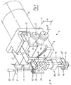
- FIG. 1 represents an entire roller stand 1 with attached drive motor 2 and adjusting means 3 in perspective.
- the roller stand 1 has a fixed bearing block 4 and a U-shaped yoke 5, in each of which the working rollers of two pairs of working rollers 6, 6 'and 7, 7' are mounted.
- the two pairs of work rolls are a pair of beads 7, 7 'and a pair of flanges 6, 6' and have a movable axis 9 in the crosspiece of the yoke 5 and a fixed axis 8 in common.
- the beading roller 7 and the flanging roller 6 are mounted on the same shaft 10 which is coaxial with the axis 8 and which is rotatably mounted in the fixed bearing block 4.
- the bead roller 7 'and the flanging roller 6' are mounted on a shaft 11 which is coaxial with the axis 9 and which is rotatably mounted in the yoke 5.
- the yoke 5 is pivotally mounted on the fixed bearing block 4 with its legs on a pivot pin 12 parallel to the axes 8 and 9.
- a tension rod 13 is connected to the yoke 5 with a bent leg 13 ′, which is approximately parallel to a plane, formed by the axes 8 and 9, in front of the roller stand 1.
- a pressure piston cylinder 14 is articulated on a cantilever part 13 ′′ firmly connected to the pull rod 13, via its piston rod 15 and a tab 16 on a pivot pin 17 arranged on the cantilever part 13 ′′. Furthermore, the pressure piston cylinder 14 is firmly supported by means of a retaining bolt 19 in a side plate 20 fastened to the fixed bearing block 4. In the side plate 20, a shaft 21 is also rotatably mounted, on which an eccentric 22 and an adjusting lever 23 is attached. With the structure shown, there are now two opposing forces. The pressure in the pressure piston cylinder 14, via the piston rod 15, causes a downward pressure force in the position shown, according to arrow 24, which causes the distance X between the axes 8 and 9 to be reduced.
- the adjusting lever 23 is preferably provided with a setting scale (not shown) so that an earlier value can be reset at any time.
- a remotely controllable adjustment drive for example an electric eccentric adjustment, can also be used instead of the manually operated adjustment lever 23.
- Both roller stands 1, 1 'each have opposite pairs of beading rollers 7, 7' or flanging rollers 6, 6 ', in Figure 2 the two beading roller pairs 7, 7' are in use for the simultaneous beading of a sheet 29, for which the Roller stands 1, 1 'are set to a working distance L.
- a bead 30 formed in the process is shown enlarged in FIG. 6B.
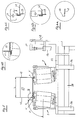
- FIGS. 3 and 4 show how the roller stand 1 is connected to the drive motor 2 via a turntable 31, the turntable 31 being held in a plurality of guide rollers 32 which are arranged on an upright cheek 33 of a sliding table 34.
- the sliding table 34 has a slide 35 which can be moved horizontally together with the roller stand 1.
- a reversing drive 36 which is designed, for example, as a simple pneumatic or hydraulic cylinder and is articulated on the displacement table 34, can now turn the entire roller stand 1 together with the drive motor 2 through an angle of approximately 90 ° (FIG. 5) without the motor Drive interrupted or the distance between the work rolls is changed.
- the drive motor is via a flange 37 2 rigidly connected to the fixed bearing block 4 by screws 38.
- a drive bevel gear 40 Arranged on a drive shaft 39 is a drive bevel gear 40 which, via an overdrive bevel gear 41, drives a shaft 42 arranged at right angles to the drive shaft 39 and a gear 43 rigidly wedged thereon.
- An overdrive spur gear 44 and a gear 45 mesh with the gear 43.
- a gear 46 also meshes with the overdrive gear 44.
- the gear wheels 45 and 46 are each connected in a rotationally fixed manner to one of the shafts 10, 11 and drive the pairs of work rollers 6, 6 'and 7, 7'.
- the whole gear set has a double reduction.
- the two roller stands 1, 1 ' are turned by the turning drive 36 by about 90 ° or by an angle ⁇ , so that the flanging rollers 6, 6' are in use in this position.
- the two roller stands 1, 1' are also set at the desired distance L in FIG. 5 for the flanging operation, so that the sheet 29 is in turn machined on both sides simultaneously can.
- the fold is closed with the flanging rollers 6, 6 'on the sheet metal sides facing away from one another.
- Two sheet metal parts, namely the sheet 29 and a side sheet 47 are closed to form an essentially tight connection. Before the sheet metal parts are closed, several operations are required.
- the side part 47 must first be provided with a side fold 48 according to FIG. 6A. Thereafter, the beads 30 are pressed in on the sheet 29 on both sides, possibly via two to three depth settings, as shown in FIG. 6B.
- FIG. 5 shows a further combination with a stapling device 49, which is actuated by a pressure cylinder 50, a stapling pliers 51.
- the stapling device 49 is attached directly to the machine stand 28, so that the work sequence is possible with the shortest possible travel distance.
- the attachment of the stitching points is shown on a larger scale in FIGS. 6C and 6D.
- the subsequent closing of the fold is shown in FIG. 6E.
- both pairs of work rolls can each be mounted in a pivotable yoke 5 via pivot pins 12 with a correspondingly designed fixed bearing block 4, the setting means 3 being able to be designed essentially in accordance with FIG.
Abstract
Description
Die Erfindung betrifft eine Blechwalzmaschine gemäss dem Oberbegriff des Anspruches 1.The invention relates to a sheet metal rolling machine according to the preamble of
Sicken und Bördeln sind bekannte Bearbeitungsvorgänge an dünnen Blechen. In beiden Fällen werden Maschinen von identischem Grundaufbau verwendet. Zwei zusammenarbeitende und angetriebene Rollen, die je nach ihrer Form und ihrer gegenseitigen Ausrichtung, im einen Fall den Rand eines Blechstreifens, entweder eine Sickenform oder im anderen Fall eine Bördelform geben, wobei ein einzelnes Blechteil meistens nur die eine oder die andere Form aufweist. Vielfach können an entsprechenden Blechwalzmaschinen Sickenrollen und/oder Bördelrollen als Schnellwechselsätze aus- und eingebaut werden. Im Falle von Rundmaschinen können Sicken gleichzeitig mit dem Rollvorgang gegebenenfalls auf beiden Seiten einer entsprechenden Rohrform angebracht werden. Bei den meisten Spezialformen dagegen führt man die Blechteile zwei oder mehrmals durch ein entsprechendes Rollenpaar. Das Sicken und Bördeln ist bis heute ein Arbeitsvorgang geblieben, der nur bei Standartformaten ökonomisch durchführbar ist, für eine grosse Anzahl von Spezialformaten aber sehr viel Umstellzeit erfordert.Beading and flanging are well-known processes on thin sheets. In both cases, machines with an identical basic structure are used. Two cooperating and driven rollers, which depending on their shape and their mutual alignment, in one case the edge of a sheet metal strip, give either a bead shape or in the other case a flanged shape, whereby a single sheet metal part usually only has one or the other shape. In many cases, beading rollers and / or flanging rollers can be removed and installed as quick-change kits on corresponding sheet metal rolling machines. In the case of round machines, beads can be attached to both sides of a corresponding tube shape at the same time as the rolling process. With most special shapes, however, the sheet metal parts are passed two or more times through a corresponding pair of rollers. The beading and flanging has remained a work process that can only be carried out economically with standard formats, but requires a lot of changeover time for a large number of special formats.
Der Erfindung wurde nun die Aufgabe gestellt, Blechwalzmaschinen zu verbessern, so dass bei grösstmöglicher Stabilität der Maschine Verstellungen rasch und leicht durchführbar und für eine Mehrzahl der Fälle die Bördel- und Sickarbeit ökonomisch durchführbar ist.The object of the invention was now to improve sheet metal rolling machines so that adjustments can be made quickly and easily with the greatest possible stability of the machine and the flanging and beading work can be carried out economically for a majority of the cases.
Diese Aufgabe wird gelöst durch die kennzeichnenden Merkmale des Anspruches 1.This object is achieved by the characterizing features of
Dadurch, dass eine Arbeitsrolle an einem Joch gelagert ist, welches vorzugsweise die Form eines verwindungssteifen, starren, U-förmigen Körpers aufweist, kann das Rollengerüst mit vergleichsweise kleinen Abmessungen und grosser Stabilität ausgeführt werden; entsprechend hoch ist die Präzision des Arbeitsergebnisses nebst einer raschen Verstellbarkeit der Maschine. Die Erfindung erlaubt eine ganze Anzahl besonders vorteilhafter Ausgestaltungen, so wird bevorzugt beidseits vom Joch überstehend je ein Arbeitsrollenpaar angeordnet, dabei können die Jochlager parallel zu dem Arbeitsrollenlager auf der einen Seite der Arbeitsrollen und die Verstellmittel auf der gegenüberliegenden Seite der Arbeitsrollen angeordnet werden.The fact that a work roll is mounted on a yoke, which preferably has the shape of a torsion-resistant, rigid, U-shaped body, enables the roll stand to be designed with comparatively small dimensions and great stability; the precision of the work result and the rapid adjustability of the machine are correspondingly high. The invention allows a number of particularly advantageous configurations, for example a pair of work rolls projecting on both sides of the yoke is preferably arranged, the yoke bearings can be arranged parallel to the work roll bearing on one side of the work rolls and the adjusting means on the opposite side of the work rolls.
Die Erfindung betrifft ferner eine Blechwalzmaschine mit zwei einseitig gelagerten und motorisch angetriebenen Arbeitsrollenpaaren, welchen Einstellmittel zugordnet sind, und ist dadurch gekennzeichnet, dass das Rollengerüst mit den Arbeitsrollen um eine Achse drehbar ausgebildet ist. Dies erlaubt verschiedene Arbeitsvorgänge mit nur minimalster Umstellzeit rationell an der selben Maschine durchzuführen, vor allem, wenn sie zwei mit einer Drehachse gegengleiche Einheiten aufweist mit je einem Satz Bördelrollen beziehungsweise Sickenrollen, welche wahlweise gegengleich zueinander einstellbar sind.The invention further relates to a sheet metal rolling machine with two motor-driven pairs of working rollers mounted on one side, to which adjusting means are assigned, and is characterized in that the roller stand with the working rollers is designed to be rotatable about an axis. This allows various work processes to be carried out efficiently on the same machine with only a minimal changeover time, especially if it has two units with the same axis of rotation, each with a set of flanging rollers or beading rollers, which can be set against each other.
Über einen einfachen Drehmechanismus können die Sickenrollen beziehungsweise Bördelrollen von einer horizontalen zu einer vertikalen Arbeitsachse umgestellt und so in einem Fall zum Beispiel beidseits eine gegengleiche Sicke, und im anderen Fall entsprechend die Blechränder, gebördelt werden. Bevorzugt ist wenigstens eine Einheit auf einer Längsschiene verschiebbar, zur Einstellung des Arbeitsabstandes der Sickenrollen beziehungsweise Bördelrollen.Using a simple rotating mechanism, the bead rolls or flanging rolls can be switched from a horizontal to a vertical working axis and, in one case, for example, an opposite bead on both sides, and in the other case the sheet edges accordingly. At least one unit can preferably be displaced on a longitudinal rail in order to adjust the working distance of the beading rolls or flanging rolls.
Die Erfindung wird nachfolgend an Hand einiger Ausführungsbeispiele mit weiteren Einzelheiten erläutert. Es zeigen:
Figur 1- ein Rollengerüst mit Antriebsmotor;
Figur 2- zwei Rollengerüste, längsverschiebbar auf einem Maschinenständer;
Figur 3- eine Seitenansicht gemäss Pfeil III der
Figur 2; - Figur 4
- einen Schnitt IV - IV der
Figur 3; Figur 5- die Einrichtung gemäss
Figur 2 jedoch mit um 90° verschwenkten Rollengerüsten und - Figur 6 A - E
- Detail VI us
Figur 2 und 5 zur Darstellung der verschiedenen Arbeitseingriffe für eine Blechverbindung in vergrössertem Massstab.
- Figure 1
- a roller stand with drive motor;
- Figure 2
- two roller stands, longitudinally displaceable on a machine stand;
- Figure 3
- a side view according to arrow III of Figure 2;
- Figure 4
- a section IV - IV of Figure 3;
- Figure 5
- the device according to FIG. 2, however, with roller stands pivoted through 90 ° and
- Figure 6 A - E
- Detail VI us Figures 2 and 5 to illustrate the various work interventions for a sheet metal connection on an enlarged scale.
In der Folge wird nun auf die Figur 1 Bezug genommen, die in Perspektive ein ganzes Rollengerüst 1 mit angebautem Antriebsmotor 2 sowie Einstellmittel 3 darstellt. Das Rollengerüst 1 weist einen Festlagerblock 4 sowie ein U-förmiges Joch 5 auf, in welchen je die Arbeitsrollen von zwei Arbeitsrollenpaaren 6, 6' beziehungsweise 7, 7' gelagert ist. Die zwei Arbeitsrollenpaare sind ein Sickenrollenpaar 7, 7' sowie ein Bördelrollenpaar 6, 6' und haben eine bewegliche Achse 9 im Quersteg des Joches 5 und eine feste Achse 8 gemeinsam.In the following, reference is now made to FIG. 1, which represents an
Die Sickenrolle 7 sowie die Bördelrolle 6 sind an der gleichen zur Achse 8 koaxialen Welle 10 montiert, welche drehbar im Festlagerblock 4 gelagert ist. Entsprechend sind die Sickenrolle 7' sowie die Bördelrolle 6' an einer zur Achse 9 koaxialen Welle 11 montiert, welche drehbar im Joch 5 gelagert ist. Das Joch 5 ist mit seinen Schenkeln an einem zu den Achsen 8 und 9 parallelen Schwenkzapfen 12 schwenkbar am Festlagerblock 4 gelagert. Mit dem Joch 5 ist ein Zugstab 13 mit einem abgekröpften Schenkel 13' verbunden, der sich etwa parallel zu einer Ebene, gebildet durch die Achsen 8 und 9, vor dem Rollengerüst 1 befindet. An einem mit dem Zugstab 13 fest verbundenen Kragteil 13'' ist ein Druckkolbenzylinder 14, über dessen Kolbenstange 15 sowie eine Lasche 16 an einem am Kragteil 13'' angeordneten Drehzapfen 17 angelenkt. Ferner ist der Druckkolbenzylinder 14 mittels eines Haltebolzens 19 in einer am Festlagerblock 4 befestigten Seitenplatte 20 fest abgestützt. In der Seitenplatte 20 ist ferner eine Welle 21 drehbar gelagert, an welcher ein Exzenter 22 sowie ein Verstellhebel 23 befestigt ist. Mit dem dargestellten Aufbau ergeben sich nun zwei entgegengesetzte Krafteinwirkungen. Der Druck im Druckkolbenzylinder 14 bewirkt über die Kolbenstange 15 in der dargestellten Lage eine Druckkraft, gemäss Pfeil 24, nach unten, was bewirkt, dass der Abstand X zwischen den Achsen 8 und 9 verkleinert wird. Die freie Bewegung des Zugstabes 13 respektiv des Joches 5 wird jedoch durch einen mit dem Zugstab 13 fest verbundenen Anschlag 25 gehindert, welcher unmittelbar am Exzenter 22 anliegt. Die bei den Arbeitsrollen 6,6' ,7,7' auftretenden Walzkräfte, welche entgegengesetzt zu Pfeil 24 wirken, werden durch den Zugstab 13 vom Druckkolbenzylinder 14 abgefangen, so dass unabhängig von der Grösse der Walzkräfte der Abstand X konstant bleibt. Muss jedoch der Abstand X verändert werden, kann durch ein Verschwenken des Verstellhebels 23, (Pfeil 26) mit einem entsprechenden Verdrehen des Exzenters 22 der je gewünschte, neue Abstand X eingestellt werden.The beading
Bevorzugt ist der Verstellhebel 23 mit einer nicht dargestellten Einstellskala versehen, so dass jederzeit ein früherer Wert wiedereingestellt werden kann. Selbstverständlich kann anstelle des handbetätigten Verstellhebels 23 auch ein fernsteuerbarer Verstellantrieb, zum Beispiel eine elektrische Exzenterverstellung, eingesetzt werden.The adjusting
In der Figur 2 sind zwei Rollengerüste 1, 1' an einer Längsschiene 27 eines Maschinenständers 28 horizontal verschiebbar angeordnet. Beide Rollengerüste 1, 1' weisen je gegengleiche Paare von Sickenrollen 7, 7' respektiv Bördelrollen 6, 6' auf, wobei in der Figur 2 die beiden Sickenrollenpaare 7, 7' im Arbeitseinsatz sind für das gleichzeitige Sicken eines Bleches 29, für welches die Rollengerüste 1, 1' auf einen Arbeitsabstand L eingestellt sind. Eine dabei gebildete Sicke 30 ist vergrössert in Figur 6B dargestellt.In FIG. 2, two roller stands 1, 1 'are arranged horizontally displaceably on a
Die Figur 3 und 4 zeigen wie das Rollengerüst 1 über einen Drehkranz 31 mit dem Antriebsmotor 2 verbunden ist, wobei der Drehkranz 31 in mehreren Führungsrollen 32 gehalten ist, welche an einer aufrechten Wange 33 eines Verschiebetisches 34 angeordnet sind. Der Verschiebetisch 34 weist einen Schlitten 35 auf, welcher zusammen mit dem Rollengerüst 1 horizontal verfahrbar ist. Ein Wendeantrieb 36, welcher zum Beispiel als einfacher Pneumatik- oder Hydraulikzylinder ausgebildet und an dem Verschiebetisch 34 angelenkt ist, kann nun das ganze Rollengerüst 1 zusammen mit dem Antriebsmotor 2 um einen Winkel von etwa 90° wenden (Figur 5), ohne dass der motorische Antrieb unterbrochen oder der Abstand der Arbeitsrollen dadurch geändert wird. Über einen Flansch 37 ist der Antriebsmotor 2 durch Schrauben 38 starr mit dem Festlagerblock 4 verbunden. An einer Antriebswelle 39 ist ein Antriebskegelrad 40 angeordnet, welches über ein Übertriebskegelrad 41 eine im rechten Winkel zu der Antriebswelle 39 angeordnete Welle 42 sowie ein darauf starr aufgekeiltes Zahnrad 43 antreibt. Mit dem Zahnrad 43 ist ein Übertriebsstirnrad 44 und ein Zahnrad 45 in Eingriff. Mit dem Übertriebszahnrad 44 kämmt weiter ein Zahnrad 46. Die Zahnräder 45 beziehungsweise 46 sind je drehfest mit einer der Wellen 10, 11 verbunden und treiben die Arbeitsrollenpaare 6,6' beziehungsweise 7,7' an. Der ganze Getriebesatz weist eine zweifache Untersetzung auf.FIGS. 3 and 4 show how the
In der Figur 5 sind die beiden Rollengerüste 1, 1' durch den Wendeantrieb 36 um etwa 90° respektiv um einen Winkel α gewendet, so dass in dieser Stellung die Bördelrollen 6, 6' im Arbeitseinsatz sind. Entsprechend der Lage der beiden Rollengerüste 1, 1' in der Figur 2 werden auch in der Figur 5 für den Bördeleinsatz die beiden Rollengerüste 1, 1' in dem hier gewünschten Abstand L eingestellt, so dass das Blech 29 wiederum auf beiden Seiten gleichzeitig bearbeitet werden kann. Bei dem in der Figur 5 dargestellten Arbeitsvorgang wird mit den Bördelrollen 6,6' der Falz auf den einander abgewandten Blechseiten geschlossen. Dabei werden zwei Blechteile, nämlich das Blech 29 sowie ein Seitenblech 47, zu einer im wesentlichen dichten Verbindung geschlossen. Vorgängig dem Schliessen der Blechteile sind mehrere Arbeitsvorgänge erforderlich. Das Seitenteil 47 muss zuerst entsprechend Figur 6A mit einem seitlichen Falz 48 versehen werden. Danach werden an dem Blech 29 beidseits über gegebenenfalls zwei bis drei Tiefeneinstellungen die Sicken 30 gemäss Figur 6B eingedrückt.In Figure 5, the two roller stands 1, 1 'are turned by the turning
Die Seitenteile 47 können nun gemäss Figur 6C in die vorbereitete Sicke 30 eingelegt werden. Vor dem Schliessen des Falzes müssen die beiden Teile durch drei bis vier Heftstellen verbunden werden, damit bei dem Schliessen die genaue, gewünschte Lage erhalten bleibt. In der Figur 5 ist hierzu eine weitere Kombination mit einer Hefteinrichtung 49, welche durch einen Druckzylinder 50, eine Heftzange 51 betätigt wird, dargestellt. Die Hefteinrichtung 49 ist direkt an dem Maschinenständer 28 befestigt, so dass die Arbeitsfolge mit kürzestmöglichem Arbeitsweg möglich ist. Das Anbringen der Heftstellen ist in den Figuren 6C und 6D in grösserem Massstab dargestellt. Das nachfolgende Schliessen des Falzes zeigt Figur 6E. Versuche haben bestätigt, dass die erfindungsgemässe Lösung für die entsprechende Verformung von dünnen Isolierschutzblechen in Zusammenarbeit mit der Herstellung von Isolierrohren ganz besonders vorteilhaft ist. Es kann mit der grösst möglichen Flexibilität und der geringst möglichen Umstellzeit eine sehr grosse Vielfalt an "massgeschneiderten" Formteilen präzise und schnell hergestellt werden.The
Gemäss einem weiteren nicht dargestellten Ausführungsgedanken können beide Arbeitsrollenpaare in je einem verschwenkbaren Joch 5 über Schwenkzapfen 12 mit einem entsprechend ausgebildeten Festlagerblock 4 angebracht werden, wobei die Einstellmittel 3 im wesentlichen entsprechend der Figur 1 konzipiert sein können.According to a further embodiment, not shown, both pairs of work rolls can each be mounted in a
Claims (14)
dadurch gekennzeichnet,
dass wenigstens eine der Arbeitsrollen (6, 6', 7, 7') eines Arbeitsrollenpaares an einem um einen Festlagerblock (4) des Rollengerüstes (1) verschwenkbaren, vorzugsweise U-förmigen Joch (5) relativ zur anderen beweglich gelagert ist, wobei die Einstellmittel (3) am Joch (5) und am Festlagerblock (4) abgestützt sind.Sheet metal rolling machine for beading, flanging and the like of thin sheets with motor-driven work rolls (6, 6 ', 7, 7') mounted in a roller stand (1), which can be adjusted relative to one another via adjustment means (3) for the bead depth,
characterized,
that at least one of the work rolls (6, 6 ', 7, 7') of a pair of work rolls is movably mounted relative to the other on a preferably U-shaped yoke (5) which can be pivoted about a fixed bearing block (4) of the roll stand (1), the Adjustment means (3) on the yoke (5) and on the fixed bearing block (4) are supported.
dadurch gekennzeichnet,
dass beidseits vom Joch (5) überstehend je eine Arbeitsrolle (6', 7') eines Arbeitsrollenpaares (6, 6', 7, 7') angeordnet ist.Sheet rolling machine according to claim 1,
characterized,
that a working roll (6 ', 7') of a pair of working rolls (6, 6 ', 7, 7') is arranged projecting on both sides of the yoke (5).
dadurch gekennzeichnet,
dass ein im Festlagerblock (5) angeordneter, die Schenkel des U-förmigen Joches (5) durchsetzender Schwenkzapfen (12) parallel zu den Achsen (8, 9) der Arbeitsrollen (6, 6', 7, 7') auf der einen Seite der Arbeitsrollen und die Einstellmittel (3) vorzugsweise auf der gegenüberliegenden Seite angeordnet sind.Sheet rolling machine according to claim 1 or 2,
characterized,
that a pivot pin (12) arranged in the fixed bearing block (5) and passing through the legs of the U-shaped yoke (5) parallel to the axes (8, 9) of the work rolls (6, 6 ', 7, 7') on one side the work rolls and the setting means (3) are preferably arranged on the opposite side.
dadurch gekennzeichnet,
dass die Einstellmittel (3), einen über vorzugsweise einen verstellbaren Exzenter (22) am Festlagerblock (4) einerseits und am Joch (5) anderseits abgestützten Zugstab (13), mit einem Druckkolbenzylinder (14) aufweisen.Sheet rolling machine according to claim 3,
characterized,
that the adjusting means (3) have a tension rod (13), preferably supported by an adjustable eccentric (22) on the fixed bearing block (4) on the one hand and on the yoke (5) on the other hand, with a pressure piston cylinder (14).
dadurch gekennzeichnet,
dass die Arbeitsrollen (6,6' ,7,7') einen gemeinsamen Antriebsmotor (2) aufweisen.Sheet rolling machine according to one of claims 1 to 4,
characterized,
that the work rolls (6,6 ', 7,7') have a common drive motor (2).
dadurch gekennzeichnet,
dass das Rollengerüst(1,1') um die Motorwelle schwenkbar ausgebildet ist.Sheet metal rolling machine with a roller stand, which has at least one pair of working rollers and a motor (2) oriented transversely to the drive roller axes (8, 9) with its shaft, preferably according to one of claims 1 to 5,
characterized,
that the roller stand (1, 1 ') is designed to be pivotable about the motor shaft.
dadurch gekennzeichnet,
dass das Rollengerüst (1,1') durch einen Wendeantrieb (36) um die Motorwelle in verschiedene Arbeitslagen schwenkbar ist, wobei der Verstellwinkel vorzugsweise 0 - 90° beträgt.Sheet rolling machine according to claim 6,
characterized,
that the roller stand (1, 1 ') can be pivoted around the motor shaft in various working positions by means of a reversing drive (36), the adjustment angle preferably being 0 to 90 °.
dadurch gekennzeichnet,
dass sie zwei gegengleiche Rollengerüste (1,1') mit je einem Satz Bördelrollen (6,6') beziehungsweise Sickenrollen (7,7') aufweist, welche wahlweise gegengleich zueinander einstellbar sind.Sheet rolling machine according to one of claims 6 or 7,
characterized,
that it has two opposing roller stands (1,1 '), each with a set of flanging rollers (6,6') or beading rollers (7,7 '), which can optionally be set opposite each other.
dadurch gekennzeichnet,
dass wenigstens ein Rollengerüst (1, 1') auf einer Längsschiene (27) verschiebbar ist, zur Einstellung des Arbeitsabstandes (L) der Sickenrollen (7,7') beziehungsweise Bördelrollen (6,6').Sheet rolling machine according to claim 8,
characterized,
that at least one roller stand (1, 1 ') is displaceable on a longitudinal rail (27) for setting the working distance (L) of the beading rollers (7,7') or flanging rollers (6,6 ').
dadurch gekennzeichnet,
dass sie eine, über Druckzylinder (50) betätigbare Heftvorrichtung (49) aufweist, welche an einem gemeinsamen Maschinenständer (28) abgestützt ist.Sheet rolling machine according to one of claims 6 to 9,
characterized,
that it has a stapling device (49) which can be actuated via pressure cylinder (50) and which is supported on a common machine stand (28).
dadurch gekennzeichnet,
dass der Festlagerblock (4) und der Antriebsmotor (2) durch einen Drehkranz (31) miteinander verbunden sind.Sheet rolling machine according to one of claims 6 or 7,
characterized,
that the fixed bearing block (4) and the drive motor (2) are connected to one another by a rotating ring (31).
dadurch gekennzeichnet,
dass der Drehkranz (31) über Führungsrollen (32) an einem Gleittisch (34) gelagert und an Längsschienen (27) verfahrbar ist.Sheet rolling machine according to claim 11,
characterized,
that the slewing ring (31) is mounted on a sliding table (34) via guide rollers (32) and can be moved on longitudinal rails (27).
dadurch gekennzeichnet,
dass der Antrieb der Arbeitsrollen (6,6' ,7,7') über ein Kegelzahnradpaar auf eine zu den Achsen (8,9) quer orientierten Welle (42) erfolgt, wobei die Arbeitsrollen (6,6',7,7') über einen Stirnrädersatz (43,44,45,46) antreibbar sind.Sheet metal rolling machine according to one of claims 11 or 12,
characterized,
that the work rolls (6,6 ', 7,7') are driven via a bevel gear pair on a shaft (42) oriented transversely to the axes (8,9), the work rolls (6,6 ', 7,7') ) can be driven using a spur gear set (43, 44, 45, 46).
dadurch gekennzeichnet,
dass ein Stirnradpaar des Stirnrädersatzes auf dem Schwenkzapfen (12) des Joches (5) respektiv der Achse (9) gelagert ist.Sheet rolling machine according to claim 13,
characterized,
that a spur gear pair of the spur gear set is mounted on the pivot pin (12) of the yoke (5) or the axis (9).
Applications Claiming Priority (2)
| Application Number | Priority Date | Filing Date | Title |
|---|---|---|---|
| CH2751/92 | 1992-09-02 | ||
| CH02751/92A CH686662A5 (en) | 1992-09-02 | 1992-09-02 | Sheet metal working machine. |
Publications (2)
| Publication Number | Publication Date |
|---|---|
| EP0585613A1 true EP0585613A1 (en) | 1994-03-09 |
| EP0585613B1 EP0585613B1 (en) | 1996-10-02 |
Family
ID=4240790
Family Applications (1)
| Application Number | Title | Priority Date | Filing Date |
|---|---|---|---|
| EP93112222A Expired - Lifetime EP0585613B1 (en) | 1992-09-02 | 1993-07-30 | Sheet rolling machine |
Country Status (4)
| Country | Link |
|---|---|
| EP (1) | EP0585613B1 (en) |
| AT (1) | ATE143619T1 (en) |
| CH (1) | CH686662A5 (en) |
| DE (1) | DE59304036D1 (en) |
Cited By (8)
| Publication number | Priority date | Publication date | Assignee | Title |
|---|---|---|---|---|
| EP1518616A3 (en) * | 2003-09-25 | 2005-04-20 | Mabi Ag | Sheet rolling machine for forming beads, edges and the like on metal sheets |
| CN104907380A (en) * | 2015-06-12 | 2015-09-16 | 江阴职业技术学院 | Drive mechanism of arc-plate flanging machine |
| CN104959484A (en) * | 2015-06-16 | 2015-10-07 | 上海君屹工业自动化股份有限公司 | Automobile wheel cover edge rolling device |
| CN106238538A (en) * | 2016-10-10 | 2016-12-21 | 济南纽兰数控机械有限公司 | Arc plate flanger |
| CN108043929A (en) * | 2017-12-13 | 2018-05-18 | 潍坊江钢机械有限公司 | Foot control channelling machine |
| CN109731960A (en) * | 2019-01-10 | 2019-05-10 | 凌云工业股份有限公司上海凌云汽车研发分公司 | The roller arc device of automobile opening bumper |
| CN112845753A (en) * | 2020-12-22 | 2021-05-28 | 吴宗禹 | Automatic change aluminum plate shaping blank holder machine |
| CN114378535A (en) * | 2022-01-13 | 2022-04-22 | 北京城建集团有限责任公司 | Construction method for pipeline groove connection |
Families Citing this family (1)
| Publication number | Priority date | Publication date | Assignee | Title |
|---|---|---|---|---|
| DE102019129790A1 (en) | 2019-11-05 | 2021-05-06 | Opitz Packaging Systems Gmbh | Creasing station and method for the automatic creasing of a folding box with inserted packaged goods |
Citations (5)
| Publication number | Priority date | Publication date | Assignee | Title |
|---|---|---|---|---|
| DE2549516A1 (en) * | 1975-11-05 | 1977-05-12 | Leifeld & Co | Multiple seam pressing machine for barrels - has columns on machine bed for adjustably ribbed rotary seam press drum tool |
| DE2704633A1 (en) * | 1977-02-04 | 1978-08-10 | Blomberg Werke Kg | Tool system for folding sheet metal containers - has holder for shell and rollers joining ends with rounded corners |
| US4279211A (en) * | 1979-07-23 | 1981-07-21 | Roll Former Corporation | Controllably driven seamer |
| DE8708142U1 (en) * | 1987-06-09 | 1987-07-30 | Siegwart, Emil, 6605 Friedrichsthal, De | |
| US4726107A (en) * | 1987-07-06 | 1988-02-23 | Knudson Gary Art | Seaming apparatus |
-
1992
- 1992-09-02 CH CH02751/92A patent/CH686662A5/en not_active IP Right Cessation
-
1993
- 1993-07-30 AT AT93112222T patent/ATE143619T1/en not_active IP Right Cessation
- 1993-07-30 DE DE59304036T patent/DE59304036D1/en not_active Expired - Lifetime
- 1993-07-30 EP EP93112222A patent/EP0585613B1/en not_active Expired - Lifetime
Patent Citations (5)
| Publication number | Priority date | Publication date | Assignee | Title |
|---|---|---|---|---|
| DE2549516A1 (en) * | 1975-11-05 | 1977-05-12 | Leifeld & Co | Multiple seam pressing machine for barrels - has columns on machine bed for adjustably ribbed rotary seam press drum tool |
| DE2704633A1 (en) * | 1977-02-04 | 1978-08-10 | Blomberg Werke Kg | Tool system for folding sheet metal containers - has holder for shell and rollers joining ends with rounded corners |
| US4279211A (en) * | 1979-07-23 | 1981-07-21 | Roll Former Corporation | Controllably driven seamer |
| DE8708142U1 (en) * | 1987-06-09 | 1987-07-30 | Siegwart, Emil, 6605 Friedrichsthal, De | |
| US4726107A (en) * | 1987-07-06 | 1988-02-23 | Knudson Gary Art | Seaming apparatus |
Cited By (10)
| Publication number | Priority date | Publication date | Assignee | Title |
|---|---|---|---|---|
| EP1518616A3 (en) * | 2003-09-25 | 2005-04-20 | Mabi Ag | Sheet rolling machine for forming beads, edges and the like on metal sheets |
| EP1724033A2 (en) * | 2003-09-25 | 2006-11-22 | Mabi Ag | Machine for forming beads, edges and the like on metal sheets |
| EP1724033A3 (en) * | 2003-09-25 | 2006-11-29 | Mabi Ag | Machine for forming beads, edges and the like on metal sheets |
| CN104907380A (en) * | 2015-06-12 | 2015-09-16 | 江阴职业技术学院 | Drive mechanism of arc-plate flanging machine |
| CN104959484A (en) * | 2015-06-16 | 2015-10-07 | 上海君屹工业自动化股份有限公司 | Automobile wheel cover edge rolling device |
| CN106238538A (en) * | 2016-10-10 | 2016-12-21 | 济南纽兰数控机械有限公司 | Arc plate flanger |
| CN108043929A (en) * | 2017-12-13 | 2018-05-18 | 潍坊江钢机械有限公司 | Foot control channelling machine |
| CN109731960A (en) * | 2019-01-10 | 2019-05-10 | 凌云工业股份有限公司上海凌云汽车研发分公司 | The roller arc device of automobile opening bumper |
| CN112845753A (en) * | 2020-12-22 | 2021-05-28 | 吴宗禹 | Automatic change aluminum plate shaping blank holder machine |
| CN114378535A (en) * | 2022-01-13 | 2022-04-22 | 北京城建集团有限责任公司 | Construction method for pipeline groove connection |
Also Published As
| Publication number | Publication date |
|---|---|
| DE59304036D1 (en) | 1996-11-07 |
| EP0585613B1 (en) | 1996-10-02 |
| ATE143619T1 (en) | 1996-10-15 |
| CH686662A5 (en) | 1996-05-31 |
Similar Documents
| Publication | Publication Date | Title |
|---|---|---|
| DE3544056A1 (en) | BENDING MACHINE | |
| DE3042383C2 (en) | ||
| EP0585613B1 (en) | Sheet rolling machine | |
| DE1452946A1 (en) | Glaet rolling device | |
| DE1948806A1 (en) | Gear rolling device | |
| DE2537382A1 (en) | DEVICE FOR BENDING PIPES | |
| WO1992000154A1 (en) | Folding press for bending and shaping sheet metal | |
| EP0497780B1 (en) | Process for the two-directional bending of sheet metal | |
| EP2145706B1 (en) | Apparatus for straightening metallic articles | |
| EP1490186A1 (en) | Bending machine for profiles and circular pipes | |
| DE2017557A1 (en) | Stretching machine for stretch drawing and straightening metal sheets and plates | |
| EP0986440B1 (en) | Folding machine | |
| DE2409833C3 (en) | Chain welding machine | |
| DE3342189C2 (en) | ||
| DE19853294A1 (en) | Device for the stretch bending of metal bars or profiles | |
| DE1627586A1 (en) | Roll bending machine | |
| DE2419231B2 (en) | Device for incremental grid transport by different amounts in a grid welding machine | |
| DE909564C (en) | Machine for bending thin-walled open metal profiles | |
| DE2714652A1 (en) | SCREEN PRINTING DEVICE | |
| DE2252467C3 (en) | ||
| DE170210C (en) | ||
| DE511941C (en) | Dough strand rolling machine | |
| EP1393831B1 (en) | Apparatus for bending hollow profiles | |
| DE1452867C (en) | Adjustment device on plate leveling machines for the leveling roll planes in three degrees of freedom | |
| DE40828C (en) | Machine for cutting boards from round wood |
Legal Events
| Date | Code | Title | Description |
|---|---|---|---|
| PUAI | Public reference made under article 153(3) epc to a published international application that has entered the european phase |
Free format text: ORIGINAL CODE: 0009012 |
|
| AK | Designated contracting states |
Kind code of ref document: A1 Designated state(s): AT BE DE DK FR IT NL |
|
| 17P | Request for examination filed |
Effective date: 19940825 |
|
| 17Q | First examination report despatched |
Effective date: 19950327 |
|
| GRAH | Despatch of communication of intention to grant a patent |
Free format text: ORIGINAL CODE: EPIDOS IGRA |
|
| GRAH | Despatch of communication of intention to grant a patent |
Free format text: ORIGINAL CODE: EPIDOS IGRA |
|
| GRAA | (expected) grant |
Free format text: ORIGINAL CODE: 0009210 |
|
| AK | Designated contracting states |
Kind code of ref document: B1 Designated state(s): AT BE DE DK FR IT NL |
|
| PG25 | Lapsed in a contracting state [announced via postgrant information from national office to epo] |
Ref country code: NL Free format text: LAPSE BECAUSE OF FAILURE TO SUBMIT A TRANSLATION OF THE DESCRIPTION OR TO PAY THE FEE WITHIN THE PRESCRIBED TIME-LIMIT Effective date: 19961002 Ref country code: DK Effective date: 19961002 |
|
| REF | Corresponds to: |
Ref document number: 143619 Country of ref document: AT Date of ref document: 19961015 Kind code of ref document: T |
|
| REF | Corresponds to: |
Ref document number: 59304036 Country of ref document: DE Date of ref document: 19961107 |
|
| ITF | It: translation for a ep patent filed |
Owner name: STUDIO INGG. FISCHETTI & WEBER |
|
| ET | Fr: translation filed | ||
| NLV1 | Nl: lapsed or annulled due to failure to fulfill the requirements of art. 29p and 29m of the patents act | ||
| PG25 | Lapsed in a contracting state [announced via postgrant information from national office to epo] |
Ref country code: AT Free format text: LAPSE BECAUSE OF NON-PAYMENT OF DUE FEES Effective date: 19970730 |
|
| PG25 | Lapsed in a contracting state [announced via postgrant information from national office to epo] |
Ref country code: BE Effective date: 19970731 |
|
| PLBE | No opposition filed within time limit |
Free format text: ORIGINAL CODE: 0009261 |
|
| STAA | Information on the status of an ep patent application or granted ep patent |
Free format text: STATUS: NO OPPOSITION FILED WITHIN TIME LIMIT |
|
| 26N | No opposition filed | ||
| BERE | Be: lapsed |
Owner name: MABI A.G. ISOLIERMASCHINEN Effective date: 19970731 |
|
| PGFP | Annual fee paid to national office [announced via postgrant information from national office to epo] |
Ref country code: IT Payment date: 20120727 Year of fee payment: 20 Ref country code: FR Payment date: 20120806 Year of fee payment: 20 Ref country code: DE Payment date: 20120720 Year of fee payment: 20 |
|
| REG | Reference to a national code |
Ref country code: DE Ref legal event code: R071 Ref document number: 59304036 Country of ref document: DE |
|
| PG25 | Lapsed in a contracting state [announced via postgrant information from national office to epo] |
Ref country code: DE Free format text: LAPSE BECAUSE OF EXPIRATION OF PROTECTION Effective date: 20130731 |