EP0585276B1 - Device for cleaning synthetic grass playing surfaces - Google Patents
Device for cleaning synthetic grass playing surfaces Download PDFInfo
- Publication number
- EP0585276B1 EP0585276B1 EP92909724A EP92909724A EP0585276B1 EP 0585276 B1 EP0585276 B1 EP 0585276B1 EP 92909724 A EP92909724 A EP 92909724A EP 92909724 A EP92909724 A EP 92909724A EP 0585276 B1 EP0585276 B1 EP 0585276B1
- Authority
- EP
- European Patent Office
- Prior art keywords
- particulate matter
- manifold
- air
- coarse
- playing surface
- Prior art date
- Legal status (The legal status is an assumption and is not a legal conclusion. Google has not performed a legal analysis and makes no representation as to the accuracy of the status listed.)
- Expired - Lifetime
Links
Images


Classifications
-
- A—HUMAN NECESSITIES
- A47—FURNITURE; DOMESTIC ARTICLES OR APPLIANCES; COFFEE MILLS; SPICE MILLS; SUCTION CLEANERS IN GENERAL
- A47L—DOMESTIC WASHING OR CLEANING; SUCTION CLEANERS IN GENERAL
- A47L9/00—Details or accessories of suction cleaners, e.g. mechanical means for controlling the suction or for effecting pulsating action; Storing devices specially adapted to suction cleaners or parts thereof; Carrying-vehicles specially adapted for suction cleaners
- A47L9/02—Nozzles
- A47L9/08—Nozzles with means adapted for blowing
-
- A—HUMAN NECESSITIES
- A47—FURNITURE; DOMESTIC ARTICLES OR APPLIANCES; COFFEE MILLS; SPICE MILLS; SUCTION CLEANERS IN GENERAL
- A47L—DOMESTIC WASHING OR CLEANING; SUCTION CLEANERS IN GENERAL
- A47L5/00—Structural features of suction cleaners
- A47L5/12—Structural features of suction cleaners with power-driven air-pumps or air-compressors, e.g. driven by motor vehicle engine vacuum
- A47L5/14—Structural features of suction cleaners with power-driven air-pumps or air-compressors, e.g. driven by motor vehicle engine vacuum cleaning by blowing-off, also combined with suction cleaning
-
- E—FIXED CONSTRUCTIONS
- E01—CONSTRUCTION OF ROADS, RAILWAYS, OR BRIDGES
- E01H—STREET CLEANING; CLEANING OF PERMANENT WAYS; CLEANING BEACHES; DISPERSING OR PREVENTING FOG IN GENERAL CLEANING STREET OR RAILWAY FURNITURE OR TUNNEL WALLS
- E01H1/00—Removing undesirable matter from roads or like surfaces, with or without moistening of the surface
- E01H1/08—Pneumatically dislodging or taking-up undesirable matter or small objects; Drying by heat only or by streams of gas; Cleaning by projecting abrasive particles
- E01H1/0863—Apparatus loosening or removing the dirt by blowing and subsequently dislodging it at least partially by suction ; Combined suction and blowing nozzles
Definitions
- This invention relates to the renovation of synthetic playing surfaces particulary, but not exclusively, sporting surfaces such as synthetic grass tennis courts, synthetic bowling greens and synthetic football and like playing fields, which generally include a layer of sand or other coarse particulate matter as part of their structural make up.
- the invention is primarily concerned with equipment for removing the coarse particulate matter, together with any entrained dirt, from the synthetic grass surface, separating the dirt from the sand, and returning the clean particulate matter to the synthetic grass surface.
- Another aspect of the invention concerns equipment for softening the layer of sand and/or other particulate matter in synthetic playing surfaces, and this aspect has particular applicability to sporting surfaces which are wet.
- Synthetic grass tennis courts typically comprise a synthetic mat surface from which extend tufts of simulated grass fibres of plastics material. Sand is layered over the mat surface filling the spaces between the tufts so that the tufts remain substantially erect and produce a flat surface which provides a ball rebound similar to a natural grass court surface.
- DE-G-8804130 describes a machine for cleaning artificial grass surfaces which includes a rotating brush to dislodge particulates from the surface and "sweep" them into a collecting box where fine particulates are filtered out, and coarse particulates are redeposited onto the surface, by the action of a blower coupled to the collection box.
- a device and method for dislodging, entraining and separating coarse and fine particulate matter layered on a synthetic playing surface as recited in claims 1 and 14 respectively.
- the device preferably comprises a plenum chamber having a compressed air inlet and at least one air outlet through which air can be expelled at an inclined angle against a playing surface so as to dislodge coarse and fine particulate matter layered thereon and to direct it into an adjacent manifold which extends above said plenum chamber, said manifold including a port located in its upper region through which the fine lightweight particulate matter is exhausted, and an outlet in a lower region by way of which the coarse heavyweight particulate matter is passed back to the playing surface.
- the particulate dislodgment, entrainment and separating device is suitably arranged on a framework which permits easy manipulation over the surface to be treated.
- An arrangement for removing the separated lightweight matter and collecting it may also be included on such a framework.
- the framework is wheeled so that the device may be pushed or driven over the surface to be treated.
- the plenum chamber is preferably an elongate chamber, most suitably of substantially tubular configuration which traverses the device from side to the other, that is, it is arranged such that it extends at approximately right angles to the direction in which the device is adapted to move or be propelled over the ground surface.
- the plenum chamber has at least one compressed air inlet, most preferably two - on opposing end walls thereof, and at least one outlet of relatively reduced size which effects an increase in the velocity of the air passing therethrough and which directs the air at an angle downwardly beneath the device against the particulate matter to be dislodged and entrained.
- the outlet may be one or more narrow slits, preferably extending in a straight line transversely of the device or, most preferably, a multiplicity of aligned pin holes.
- the internal bore of each pin hole outlet is countersunk so that a venturi effect is produced by the air passing therethrough.
- the angle at which the outlet(s) is arranged is such as to provide maximum leverage on the particulate matter to be dislodged, whilst simultaneously directing the dislodged matter towards the inlet of the adjacent manifold.
- a suitable angle is between 30° and 75°, most preferably about 60° with respect to the synthetic surface.
- the number of outlets in the plenum chamber will ideally be maximized so that a large number of individual jets of fast moving air can be directed against the particulate surface, thereby optimising the dislodgment forces thereon. This is particularly important when the particulate matter has formed a hard crusty surface as is quite common in tennis court surfaces.
- the manifold is suitably a hollow curvilinear duct of semi-cylindrical configuration with a longitudinal particulate inlet located adjacent the outlet(s) of the plenum chamber.
- the plenum chamber is suitably arranged coaxially with the duct so as to be closely spaced from the playing surface.
- baffle plates are arranged to partially enshroud the plenum chamber to prevent the coarse particulate matter from being carried into the manifold port and to direct the coarse particulate matter back onto the playing surface from which it has previously been uplifted.
- the baffle plates may take the form of curved plates arranged at spaced intervals above the plenum chamber.
- a deflector can suitably be located in the region of the particulate inlet.
- the deflector may be a planar plate which is angled with respect to the adjacent playing surface so that particulate matter striking its surface is reflected upwardly into the manifold.
- the longitudinal inlet of the manifold is suitably located in the front half or foremost section of the device and can, if need be, be covered with a grill or mesh of sufficient aperture to prevent entrainment of large pieces of debris which could conceivably block the manifold or at least impede the operation thereof. This, however, is not usually necessary.
- the manifold may include a section adjacent the longitudinal inlet which extends upwardly in a substantially vertical direction and then curves in a constant radius of curvature through a horizontal section to a downwardly directed section which defines a coarse particulate matter outlet.
- the manifold is ideally designed so that the wall adjacent the longitudinal inlet extends upwardly therefrom at a constant radius of curvature through a less curved region to a downwardly curved section which defines the outer wall at a coarse particulate outlet.
- the coarse particulate matter outlet may be sufficiently larger than the manifold inlet to enable a drop in the velocity of the air as it passes from the manifold inlet to the outlet, thereby to spread the coarse particulate matter on the playing surface in a uniform layer.
- the upper region of the manifold incorporates the port through which all lightweight matter is exhausted.
- the port is simply an opening about which a deflector or similar means can be arranged if necessary to prevent the coarse, particulate matter being sucked therethrough.
- the coarse particulate matter is directed towards the outlet in the rear section of the manifold due to its heavier and bulkier nature.
- a skirt may be provided between the bottom edge of the manifold and the ground surface. This may take the form of a flat metal plate which extends outwardly from the manifold about its entire perimeter.
- the particle dislodgment, separation and entrainment device is preferably supported on a wheeled framework.
- a wheeled framework is preferably of tubular construction with thin gauge sheet metal walls for minimising the weight of the entire apparatus.
- a push/pull handle bar is suitably provided at waist-height for easy manipulation, and means enabling the manifold to be lowered close to the ground surface or for raising it when not in use are also included.
- Such means can comprise a set of pivotal linkages operated by a lever adjacent the push/pull handle.
- a cyclone and chamber in combination with a filtering system.
- the cyclone is conveniently connected directly by way of a flexible duct to the port of the manifold.
- One form of cyclone comprises a cylinder with a conical head piece which is oriented in a vertical location on the wheeled framework between the manifold and the push/pull handle.
- An inlet is provided in the sidewall of the cyclone at an intermediate position, and internal plates direct the entrained fine particulate matter around the inner wall towards the bottom of the cyclone to a collection chamber directly beneath it.
- a filtering system is provided about an exhaust air outlet, or outlets, which is preferably located in the top of the cyclone.
- the filtering system may comprise one or more bags of filtering material supported from a framework which extends above the outlet(s).
- the filtering arrangement is designed to prevent any fine particulate matter blowing into the atmosphere while permitting the exhaust air to be expelled therethrough.
- Compressed air used to charge the plenum chamber can be supplied from a portable compressor which is either carried by the support framework for the device or is supplied by a separate remote compressor.
- a single compressed air line preferably supplies air to two separate lines connected to opposite ends of the plenum chamber, and a take-off line for driving the equipment.
- the device comprises a plenum chamber having a compressed air inlet and at least one air outlet through which air can be expelled at high velocity at an inclined angle against a playing surface so as to dislodge the particulate matter layered thereon, uplifting the particulate matter into an adjacent manifold which extends above said plenum chamber, and drop said uplifted particulate matter back onto the playing surface in a non-compacted layer.
- This device has been adapted particularly for synthetic surfaces which are wet and is therefore primarily used on winter sporting fields or those surfaces which are subjected to a lot of rain.
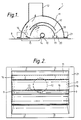
- the device indicated generally at 1, comprises a plenum chamber 10, a manifold 11 and a port 12.
- the plenum chamber 10 is a cylindrical tube which extends from one side of the device to the other in a transverse direction and has a compressed air inlet 9 at each end. It includes a multiplicity of pin hole outlets 13 through which compressed air can be directed at an inclined angle against the particulate ground surface 8, in the direction of arrow 14. This action loosens the particulate matter so that it can be uplifted at the manifold inlet 15 and be entrained in a stream of air which lifts it through the manifold as shown by the arrows. Deflector plate 16 assists in directing the particulate matter in an upward direction.
- the fine matter tends to be blown forwardly and upwardly for exhaustion through port 12, while the heavier coarser matter tends to lag behind to a certain extent and be deflected by baffles 17, 18 back on to the ground as shown by arrows 19, 20.
- the coarse particulate matter is, in fact laid back down in a similar array to that from which it was uplifted.
- a lip 21 is provided at the perimeter of the manifold to prevent any particulate matter from being blown from the side of the manifold.
- the device 1 is supported at the front end of a wheeled structure which includes means for collecting and storing the fine particulate matter as well as an air filtering arrangement and operation controls.
- the wheeled structure comprises a panelled framework 30 having a jockey wheel 31 to enable steering with handle 33, and driven wheels 32. Wheels 32 propel the structure forward when compressed air motor 34 engages the wheels through the action of belt pulley 35 which is actuated by lever 36 through a system of levers culminating in linkage arm 37.
- the interior of the wheeled structure holds the particulate collecting and storage equipment (see Figure 4 also) and is accessed through door 38.
- This equipment comprises a cyclone 40 into which is connected a flexible tube 41 extending from port 12 in the manifold of the device 1.
- the cyclone includes a number of baffles so that particulate matter in the air is separated and falls into bin 43.
- Filter socks 44 are supported from a disc 45 and encompass outlets 46 in the top of the cyclone. The filter socks remove all residual fine particulate matter from the air before it is exhausted to the atmosphere.
- the plenum chamber is supplied with compressed air by way of high pressure lines 50, 51 which extend through the interior of the wheeled structure to the rear thereof. These lines are joined at a T-piece 52 to which air is admitted by way of control valve 53 and inlet 54. Inlet 54 joins to a separate mobile compressor (not illustrated).
- a compressed air take-off compartment 55 is provided to supply air to the air motor 34.
- Lever 56 functions to raise and lower the device 1 relative to the ground surface, through a series of linkages.
- the device 40 described is particularly suitable for cleaning the sand of synthetic grass playing surfaces such as tennis courts and for cleaning the particulates from sand-free playing surfaces such as hockey fields.
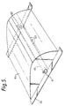
- the device depicted in Figure 5 is for softening up wet particulate material. It comprises a plenum chamber 60 having compressed air inlet 61, 62 and a plurality of pin hole outlets 63 arranged in a similar manner to those in the device depicted in Figure 1.
- the plenum chamber is located within a manifold 64 having a skirt 65. This device may be incorporated into the mobile arrangement of Figure 3 in place of the Figure 1 embodiment however since there is no outlet port the collection equipment is not utilized.
- compressed air is directed at high velocity against a wet compacted surface containing particulate matter.
- the particulate matter is uplifted and then dumped back onto the surface as the device is moved along, thereby producing a soft playing surface.
- This device is particularly suited to synthetic football and hock fields which have a sand filling.
- a typical air pressure employed with both aspects of the invention is 375 cfm at 110 psi, and the diameter of the pin holes is 1.5 mm.
Landscapes
- Engineering & Computer Science (AREA)
- Mechanical Engineering (AREA)
- Architecture (AREA)
- Civil Engineering (AREA)
- Structural Engineering (AREA)
- Cleaning In General (AREA)
- Combined Means For Separation Of Solids (AREA)
- Nozzles For Electric Vacuum Cleaners (AREA)
- Detergent Compositions (AREA)
- Cleaning By Liquid Or Steam (AREA)
- Golf Clubs (AREA)
- Road Paving Structures (AREA)
- Steering Devices For Bicycles And Motorcycles (AREA)
- Filtering Of Dispersed Particles In Gases (AREA)
- Processes For Solid Components From Exhaust (AREA)
- Electrophonic Musical Instruments (AREA)
- Motorcycle And Bicycle Frame (AREA)
- Road Repair (AREA)
- Catching Or Destruction (AREA)
Applications Claiming Priority (5)
| Application Number | Priority Date | Filing Date | Title |
|---|---|---|---|
| AUPK6212/91 | 1991-05-20 | ||
| AUPK621291 | 1991-05-20 | ||
| AU14714/92 | 1992-04-08 | ||
| AU14714/92A AU647607B2 (en) | 1991-05-20 | 1992-04-08 | Device for cleaning particulate material |
| PCT/GB1992/000890 WO1992020272A1 (en) | 1991-05-20 | 1992-05-18 | Device for cleaning synthetic grass playing surfaces |
Publications (2)
| Publication Number | Publication Date |
|---|---|
| EP0585276A1 EP0585276A1 (en) | 1994-03-09 |
| EP0585276B1 true EP0585276B1 (en) | 1996-07-10 |
Family
ID=25615509
Family Applications (1)
| Application Number | Title | Priority Date | Filing Date |
|---|---|---|---|
| EP92909724A Expired - Lifetime EP0585276B1 (en) | 1991-05-20 | 1992-05-18 | Device for cleaning synthetic grass playing surfaces |
Country Status (18)
| Country | Link |
|---|---|
| US (1) | US5562779A (enExample) |
| EP (1) | EP0585276B1 (enExample) |
| JP (1) | JP2691798B2 (enExample) |
| CN (1) | CN1067082A (enExample) |
| AT (1) | ATE140142T1 (enExample) |
| AU (1) | AU647607B2 (enExample) |
| CA (1) | CA2102111C (enExample) |
| DE (1) | DE69212153T2 (enExample) |
| DK (1) | DK0585276T3 (enExample) |
| ES (1) | ES2092683T3 (enExample) |
| FI (1) | FI97412C (enExample) |
| GR (1) | GR3021093T3 (enExample) |
| HK (1) | HK156796A (enExample) |
| IN (1) | IN185187B (enExample) |
| NO (1) | NO300301B1 (enExample) |
| NZ (1) | NZ242716A (enExample) |
| SG (1) | SG47702A1 (enExample) |
| WO (1) | WO1992020272A1 (enExample) |
Families Citing this family (23)
| Publication number | Priority date | Publication date | Assignee | Title |
|---|---|---|---|---|
| GB9021630D0 (en) * | 1990-10-04 | 1990-11-21 | Selectokil Limited | Improvements in or related to cleaning aggregates materials |
| GB9318087D0 (en) * | 1993-09-01 | 1993-10-20 | Air Force Ltd | Apparatus and method for removating playing area |
| FR2743827B1 (fr) * | 1996-01-18 | 1998-04-17 | Payen Ets | Coffret d'aspiration de sable et de feuilles, adaptable sous le chassis de tous types de microtracteurs pour l'entretien des terrains de sports synthetiques |
| DE69703010T2 (de) * | 1996-06-24 | 2001-05-10 | Smillie Beheer B.V., Bussum | Verfahren und Vorrichtung zur Behandlung von mit teilchenförmigem Material bestreuten, synthetischen Spielflächen |
| AUPO681197A0 (en) * | 1997-05-16 | 1997-06-05 | Syn-Grass Resources Pty Ltd | An apparatus for cleaning synthetic grass |
| TW475894B (en) * | 1997-12-26 | 2002-02-11 | Tec Corp | Suction port body for vacuum-cleaner and vacuum-cleaner having the same |
| US20030037388A1 (en) * | 2001-08-27 | 2003-02-27 | Feyma Daniel John | Turf equipment and method of selective debris removal from turf |
| GB0212560D0 (en) | 2002-05-31 | 2002-07-10 | Jayes Harold | Fluid pressure jetting |
| WO2004063468A1 (en) | 2003-01-09 | 2004-07-29 | Julien Jomphe | Sports surface reconditioner |
| US20050044656A1 (en) * | 2003-08-27 | 2005-03-03 | Fieldturf, Inc. | Apparatus and method for treating synthetic grass turf |
| AU2004202438B2 (en) * | 2004-06-03 | 2009-06-18 | Synthetica Holdings Pty Ltd | Apparatus for Cleaning Synthetic Grass |
| US7555812B1 (en) | 2005-02-04 | 2009-07-07 | Pinney Craig A | Brushless vacuum cleaner |
| DE202007015032U1 (de) * | 2007-10-26 | 2009-03-12 | Smg Sportplatzmaschinenbau Gmbh | Fahrbare Vorrichtung für das Ausbringen von Füllgut auf einem Kunstrasenplatz |
| WO2010060156A1 (en) * | 2008-11-28 | 2010-06-03 | Allan Allaway | A cleaning apparatus |
| US8464801B2 (en) * | 2009-06-20 | 2013-06-18 | John H. Bearden | Apparatus for collecting artificial turf for recycling |
| JP5712826B2 (ja) * | 2010-11-17 | 2015-05-07 | 株式会社リコー | 乾式クリーニング筐体及び乾式クリーニング装置 |
| DE102011082311A1 (de) * | 2011-09-07 | 2013-03-07 | Wiedenmann Gmbh | Reinigungsvorrichtung zum Reinigen von künstlichen mit Bodenbelagspartikeln versehenen Bodenflächen, insbesondere von Kunstrasen |
| PT2862688T (pt) | 2013-10-21 | 2016-10-06 | Re-Match (Uk) Ltd | Processo para a separação de um produto de relva sintética |
| US20170009414A1 (en) * | 2014-01-24 | 2017-01-12 | Synthetica Holdings Pty Ltd | Improved Apparatus for Cleaning Synthetic Grass |
| US10130089B2 (en) | 2014-07-24 | 2018-11-20 | Live Holdings LLC | Fishing caddy system and method |
| ITUB20159485A1 (it) * | 2015-12-24 | 2016-03-24 | Deco Sport S N C | Metodo e dispositivo per la rigenerazione, la sanificazione e la pulizia dei campi da gioco in erba sintetica |
| CN112411328B (zh) * | 2020-11-19 | 2022-05-17 | 广东木黄文旅体育运营管理有限公司 | 一种可均分橡胶颗粒的人造草坪养护装置 |
| CN119041337B (zh) * | 2024-10-30 | 2025-01-28 | 徐州中高环卫装备制造有限公司 | 一种用于环卫车的吸嘴组件 |
Family Cites Families (11)
| Publication number | Priority date | Publication date | Assignee | Title |
|---|---|---|---|---|
| AU4986972A (en) * | 1971-12-08 | 1974-06-13 | Michael Paul Kudinoff | Vacuum type street sweeper |
| US3902219A (en) * | 1972-05-08 | 1975-09-02 | Judson O Jones | Artificial turf cleaner |
| AU5186273A (en) * | 1973-02-06 | 1974-08-08 | Rex Grenfell Lionel | Improvements in or relating to road cleaning apparatus |
| ZA774037B (en) * | 1976-07-08 | 1978-05-30 | J Nunes | Turf grooming vehicle with dischargable receiver |
| JPS5628245U (enExample) * | 1979-08-13 | 1981-03-17 | ||
| BE890518A (fr) * | 1981-09-28 | 1982-01-18 | Staar Sa | Procede pour augmenter l'efficacite d'appareils de nettoyage par aspiration de poussieres et aspirateurs pour la mise en pratique du procede |
| DE8804130U1 (de) * | 1988-03-26 | 1988-07-14 | Riegel, Norbert, 4242 Rees | Maschine zur Reinigung von besandeten, unbesandeten Kunstrasen und lose verfüllten Belägen |
| DE3824710A1 (de) * | 1988-07-20 | 1990-01-25 | Edelhoff Polytechnik | Verfahren und vorrichtung zum reinigen von mit koernigem material bestreuten boeden von staub und schmutz |
| NZ235392A (en) * | 1989-09-20 | 1993-02-25 | Xavier John Antonio | Artificial surface treatment apparatus: scarifier and brush on same rotary shaft |
| DE9100929U1 (de) * | 1991-01-28 | 1991-04-18 | Faun Umwelttechnik GmbH, 8500 Nürnberg | Vorrichtung zum Aufsaugen von Gegenständen |
| US5302210A (en) * | 1992-04-07 | 1994-04-12 | Fraser Environmental Systems, Inc. | Rapid deployment method for recovering oil from beaches |
-
1992
- 1992-04-08 AU AU14714/92A patent/AU647607B2/en not_active Expired
- 1992-05-11 IN IN408DE1992 patent/IN185187B/en unknown
- 1992-05-12 NZ NZ242716A patent/NZ242716A/en not_active IP Right Cessation
- 1992-05-18 CA CA002102111A patent/CA2102111C/en not_active Expired - Lifetime
- 1992-05-18 AT AT92909724T patent/ATE140142T1/de not_active IP Right Cessation
- 1992-05-18 JP JP4509263A patent/JP2691798B2/ja not_active Expired - Lifetime
- 1992-05-18 ES ES92909724T patent/ES2092683T3/es not_active Expired - Lifetime
- 1992-05-18 WO PCT/GB1992/000890 patent/WO1992020272A1/en not_active Ceased
- 1992-05-18 DK DK92909724.4T patent/DK0585276T3/da active
- 1992-05-18 SG SG1996003868A patent/SG47702A1/en unknown
- 1992-05-18 EP EP92909724A patent/EP0585276B1/en not_active Expired - Lifetime
- 1992-05-18 US US08/150,080 patent/US5562779A/en not_active Expired - Lifetime
- 1992-05-18 DE DE69212153T patent/DE69212153T2/de not_active Expired - Fee Related
- 1992-05-19 CN CN92104032.6A patent/CN1067082A/zh active Pending
-
1993
- 1993-11-16 NO NO934134A patent/NO300301B1/no not_active IP Right Cessation
- 1993-11-19 FI FI935148A patent/FI97412C/fi not_active IP Right Cessation
-
1996
- 1996-08-15 HK HK156796A patent/HK156796A/en not_active IP Right Cessation
- 1996-09-19 GR GR960402453T patent/GR3021093T3/el unknown
Also Published As
| Publication number | Publication date |
|---|---|
| DE69212153D1 (de) | 1996-08-14 |
| NO300301B1 (no) | 1997-05-12 |
| FI97412C (fi) | 1996-12-10 |
| JP2691798B2 (ja) | 1997-12-17 |
| JPH06511295A (ja) | 1994-12-15 |
| DE69212153T2 (de) | 1996-11-21 |
| CN1067082A (zh) | 1992-12-16 |
| HK156796A (en) | 1996-08-23 |
| ES2092683T3 (es) | 1996-12-01 |
| GR3021093T3 (en) | 1996-12-31 |
| DK0585276T3 (da) | 1996-10-14 |
| NO934134D0 (no) | 1993-11-16 |
| IN185187B (enExample) | 2000-12-02 |
| CA2102111A1 (en) | 1992-11-21 |
| AU1471492A (en) | 1993-02-04 |
| ATE140142T1 (de) | 1996-07-15 |
| NO934134L (no) | 1993-11-16 |
| FI935148A0 (fi) | 1993-11-19 |
| WO1992020272A1 (en) | 1992-11-26 |
| SG47702A1 (en) | 1998-04-17 |
| EP0585276A1 (en) | 1994-03-09 |
| FI935148L (fi) | 1993-11-19 |
| AU647607B2 (en) | 1994-03-24 |
| FI97412B (fi) | 1996-08-30 |
| US5562779A (en) | 1996-10-08 |
| CA2102111C (en) | 2000-12-12 |
| NZ242716A (en) | 1993-07-27 |
Similar Documents
| Publication | Publication Date | Title |
|---|---|---|
| EP0585276B1 (en) | Device for cleaning synthetic grass playing surfaces | |
| US7962995B2 (en) | Apparatus for cleaning synthetic grass | |
| CA2170164C (en) | Apparatus and method for renovating playing surfaces | |
| EP0288436B1 (de) | Reinigungsfahrzeug zum Säubern von mit einem Hartbelag versehenen Bodenflächen | |
| EP2121205A1 (en) | Apparatus for on-site cleaning of landscape rock | |
| US4359801A (en) | Pick-up head for surface cleaning apparatus | |
| US20030037388A1 (en) | Turf equipment and method of selective debris removal from turf | |
| US3395467A (en) | Method and apparatus for harvesting peat moss | |
| US20170009414A1 (en) | Improved Apparatus for Cleaning Synthetic Grass | |
| US5951780A (en) | Surface treatment method and apparatus including brush means and impact means mounted on a single shaft | |
| WO2010060156A1 (en) | A cleaning apparatus | |
| CN1084417C (zh) | 吹吸式高速射流扫路机 | |
| CA1127398A (en) | olive picker | |
| HK1008752B (en) | Apparatus and method for renovating playing surfaces | |
| AU682883B2 (en) | Surface treatment apparatus including brush means and impact means mounted on a single shaft |
Legal Events
| Date | Code | Title | Description |
|---|---|---|---|
| PUAI | Public reference made under article 153(3) epc to a published international application that has entered the european phase |
Free format text: ORIGINAL CODE: 0009012 |
|
| 17P | Request for examination filed |
Effective date: 19931029 |
|
| AK | Designated contracting states |
Kind code of ref document: A1 Designated state(s): AT BE CH DE DK ES FR GB GR IT LI LU MC NL SE |
|
| 17Q | First examination report despatched |
Effective date: 19950405 |
|
| GRAH | Despatch of communication of intention to grant a patent |
Free format text: ORIGINAL CODE: EPIDOS IGRA |
|
| GRAH | Despatch of communication of intention to grant a patent |
Free format text: ORIGINAL CODE: EPIDOS IGRA |
|
| GRAA | (expected) grant |
Free format text: ORIGINAL CODE: 0009210 |
|
| ITF | It: translation for a ep patent filed | ||
| AK | Designated contracting states |
Kind code of ref document: B1 Designated state(s): AT BE CH DE DK ES FR GB GR IT LI LU MC NL SE |
|
| REF | Corresponds to: |
Ref document number: 140142 Country of ref document: AT Date of ref document: 19960715 Kind code of ref document: T |
|
| REG | Reference to a national code |
Ref country code: CH Ref legal event code: NV Representative=s name: KIRKER & CIE SA |
|
| REF | Corresponds to: |
Ref document number: 69212153 Country of ref document: DE Date of ref document: 19960814 |
|
| ET | Fr: translation filed | ||
| REG | Reference to a national code |
Ref country code: DK Ref legal event code: T3 |
|
| REG | Reference to a national code |
Ref country code: GR Ref legal event code: FG4A Free format text: 3021093 |
|
| REG | Reference to a national code |
Ref country code: ES Ref legal event code: FG2A Ref document number: 2092683 Country of ref document: ES Kind code of ref document: T3 |
|
| PLBE | No opposition filed within time limit |
Free format text: ORIGINAL CODE: 0009261 |
|
| 26N | No opposition filed | ||
| REG | Reference to a national code |
Ref country code: GB Ref legal event code: 732E |
|
| REG | Reference to a national code |
Ref country code: GB Ref legal event code: IF02 |
|
| PGFP | Annual fee paid to national office [announced via postgrant information from national office to epo] |
Ref country code: MC Payment date: 20030602 Year of fee payment: 12 |
|
| PG25 | Lapsed in a contracting state [announced via postgrant information from national office to epo] |
Ref country code: MC Free format text: LAPSE BECAUSE OF NON-PAYMENT OF DUE FEES Effective date: 20040531 |
|
| REG | Reference to a national code |
Ref country code: GB Ref legal event code: 732E |
|
| REG | Reference to a national code |
Ref country code: GB Ref legal event code: 732E |
|
| PGFP | Annual fee paid to national office [announced via postgrant information from national office to epo] |
Ref country code: DE Payment date: 20070510 Year of fee payment: 16 |
|
| PGFP | Annual fee paid to national office [announced via postgrant information from national office to epo] |
Ref country code: AT Payment date: 20070511 Year of fee payment: 16 |
|
| PGFP | Annual fee paid to national office [announced via postgrant information from national office to epo] |
Ref country code: CH Payment date: 20070516 Year of fee payment: 16 |
|
| PGFP | Annual fee paid to national office [announced via postgrant information from national office to epo] |
Ref country code: LU Payment date: 20070524 Year of fee payment: 16 |
|
| PGFP | Annual fee paid to national office [announced via postgrant information from national office to epo] |
Ref country code: ES Payment date: 20070621 Year of fee payment: 16 |
|
| REG | Reference to a national code |
Ref country code: GB Ref legal event code: 732E |
|
| PGFP | Annual fee paid to national office [announced via postgrant information from national office to epo] |
Ref country code: BE Payment date: 20070709 Year of fee payment: 16 |
|
| PGFP | Annual fee paid to national office [announced via postgrant information from national office to epo] |
Ref country code: FR Payment date: 20070510 Year of fee payment: 16 |
|
| PGFP | Annual fee paid to national office [announced via postgrant information from national office to epo] |
Ref country code: GR Payment date: 20070412 Year of fee payment: 16 |
|
| REG | Reference to a national code |
Ref country code: GB Ref legal event code: 732E |
|
| BERE | Be: lapsed |
Owner name: *AIR FORCE LTD Effective date: 20080531 |
|
| REG | Reference to a national code |
Ref country code: CH Ref legal event code: PL |
|
| PG25 | Lapsed in a contracting state [announced via postgrant information from national office to epo] |
Ref country code: LI Free format text: LAPSE BECAUSE OF NON-PAYMENT OF DUE FEES Effective date: 20080531 Ref country code: CH Free format text: LAPSE BECAUSE OF NON-PAYMENT OF DUE FEES Effective date: 20080531 |
|
| PG25 | Lapsed in a contracting state [announced via postgrant information from national office to epo] |
Ref country code: AT Free format text: LAPSE BECAUSE OF NON-PAYMENT OF DUE FEES Effective date: 20080518 |
|
| REG | Reference to a national code |
Ref country code: FR Ref legal event code: ST Effective date: 20090119 |
|
| PG25 | Lapsed in a contracting state [announced via postgrant information from national office to epo] |
Ref country code: BE Free format text: LAPSE BECAUSE OF NON-PAYMENT OF DUE FEES Effective date: 20080531 |
|
| PG25 | Lapsed in a contracting state [announced via postgrant information from national office to epo] |
Ref country code: FR Free format text: LAPSE BECAUSE OF NON-PAYMENT OF DUE FEES Effective date: 20080602 Ref country code: DE Free format text: LAPSE BECAUSE OF NON-PAYMENT OF DUE FEES Effective date: 20081202 |
|
| PG25 | Lapsed in a contracting state [announced via postgrant information from national office to epo] |
Ref country code: GR Free format text: LAPSE BECAUSE OF NON-PAYMENT OF DUE FEES Effective date: 20081204 |
|
| REG | Reference to a national code |
Ref country code: ES Ref legal event code: FD2A Effective date: 20080519 |
|
| PG25 | Lapsed in a contracting state [announced via postgrant information from national office to epo] |
Ref country code: ES Free format text: LAPSE BECAUSE OF NON-PAYMENT OF DUE FEES Effective date: 20080519 |
|
| PG25 | Lapsed in a contracting state [announced via postgrant information from national office to epo] |
Ref country code: LU Free format text: LAPSE BECAUSE OF NON-PAYMENT OF DUE FEES Effective date: 20080518 |
|
| REG | Reference to a national code |
Ref country code: NL Ref legal event code: SD Effective date: 20101013 |
|
| PGFP | Annual fee paid to national office [announced via postgrant information from national office to epo] |
Ref country code: SE Payment date: 20110512 Year of fee payment: 20 |
|
| PGFP | Annual fee paid to national office [announced via postgrant information from national office to epo] |
Ref country code: DK Payment date: 20110512 Year of fee payment: 20 Ref country code: GB Payment date: 20110518 Year of fee payment: 20 Ref country code: NL Payment date: 20110526 Year of fee payment: 20 |
|
| PGFP | Annual fee paid to national office [announced via postgrant information from national office to epo] |
Ref country code: IT Payment date: 20110516 Year of fee payment: 20 |
|
| REG | Reference to a national code |
Ref country code: NL Ref legal event code: V4 Effective date: 20120518 |
|
| REG | Reference to a national code |
Ref country code: DK Ref legal event code: EUP |
|
| REG | Reference to a national code |
Ref country code: GB Ref legal event code: PE20 Expiry date: 20120517 |
|
| REG | Reference to a national code |
Ref country code: SE Ref legal event code: EUG |
|
| PG25 | Lapsed in a contracting state [announced via postgrant information from national office to epo] |
Ref country code: GB Free format text: LAPSE BECAUSE OF EXPIRATION OF PROTECTION Effective date: 20120517 |