EP0584881B1 - Electrostatic precipitator - Google Patents
Electrostatic precipitator Download PDFInfo
- Publication number
- EP0584881B1 EP0584881B1 EP93202477A EP93202477A EP0584881B1 EP 0584881 B1 EP0584881 B1 EP 0584881B1 EP 93202477 A EP93202477 A EP 93202477A EP 93202477 A EP93202477 A EP 93202477A EP 0584881 B1 EP0584881 B1 EP 0584881B1
- Authority
- EP
- European Patent Office
- Prior art keywords
- electrodes
- precipitator
- shaped
- rod
- support
- Prior art date
- Legal status (The legal status is an assumption and is not a legal conclusion. Google has not performed a legal analysis and makes no representation as to the accuracy of the status listed.)
- Expired - Lifetime
Links
Images


Classifications
-
- B—PERFORMING OPERATIONS; TRANSPORTING
- B03—SEPARATION OF SOLID MATERIALS USING LIQUIDS OR USING PNEUMATIC TABLES OR JIGS; MAGNETIC OR ELECTROSTATIC SEPARATION OF SOLID MATERIALS FROM SOLID MATERIALS OR FLUIDS; SEPARATION BY HIGH-VOLTAGE ELECTRIC FIELDS
- B03C—MAGNETIC OR ELECTROSTATIC SEPARATION OF SOLID MATERIALS FROM SOLID MATERIALS OR FLUIDS; SEPARATION BY HIGH-VOLTAGE ELECTRIC FIELDS
- B03C3/00—Separating dispersed particles from gases or vapour, e.g. air, by electrostatic effect
- B03C3/34—Constructional details or accessories or operation thereof
- B03C3/74—Cleaning the electrodes
- B03C3/76—Cleaning the electrodes by using a mechanical vibrator, e.g. rapping gear ; by using impact
-
- B—PERFORMING OPERATIONS; TRANSPORTING
- B03—SEPARATION OF SOLID MATERIALS USING LIQUIDS OR USING PNEUMATIC TABLES OR JIGS; MAGNETIC OR ELECTROSTATIC SEPARATION OF SOLID MATERIALS FROM SOLID MATERIALS OR FLUIDS; SEPARATION BY HIGH-VOLTAGE ELECTRIC FIELDS
- B03C—MAGNETIC OR ELECTROSTATIC SEPARATION OF SOLID MATERIALS FROM SOLID MATERIALS OR FLUIDS; SEPARATION BY HIGH-VOLTAGE ELECTRIC FIELDS
- B03C3/00—Separating dispersed particles from gases or vapour, e.g. air, by electrostatic effect
- B03C3/34—Constructional details or accessories or operation thereof
- B03C3/86—Electrode-carrying means
-
- B—PERFORMING OPERATIONS; TRANSPORTING
- B03—SEPARATION OF SOLID MATERIALS USING LIQUIDS OR USING PNEUMATIC TABLES OR JIGS; MAGNETIC OR ELECTROSTATIC SEPARATION OF SOLID MATERIALS FROM SOLID MATERIALS OR FLUIDS; SEPARATION BY HIGH-VOLTAGE ELECTRIC FIELDS
- B03C—MAGNETIC OR ELECTROSTATIC SEPARATION OF SOLID MATERIALS FROM SOLID MATERIALS OR FLUIDS; SEPARATION BY HIGH-VOLTAGE ELECTRIC FIELDS
- B03C2201/00—Details of magnetic or electrostatic separation
- B03C2201/10—Ionising electrode with two or more serrated ends or sides
Definitions
- the invention relates to an electrostatic precipitator comprising a suspension device and a rapping mechanism for vertically mounted electrodes, preferably rod-shaped, tubular, helical or plate electrodes in a high-voltage supplied electrostatic precipitator for the cleaning of smoke gases from the combustion of fossil fuels, waste material and the like in industrial plants, such as for instance power supply plants, combustion plants, cement plants and the like.
- the discharge electrodes are metal electrodes and generally rod-shaped, tubular or plate electrodes or consist of wire helices and are suspended between a conductive top and a conductive bottom frame which may be connected by means of a vertical frame construction which is also conductive, said aggregate frame construction together with a corresponding frame construction for the collecting electrodes, generally plate electrodes, in the precipitator being surrounded by a precipitator housing wherein the frame constructions are secured.
- the rod-shaped, tubular or plate discharge electrodes may be provided with a number of rod- or bow-shaped protrusions over their entire length to increase the corona discharges and thus to increase the precipitator effect when the precipitator is in use.
- the frame is constituted by a comparatively heavy construction in order to support the suspended electrodes.
- the frame is suspended by means of vertical rods in insulators which are mounted in or on the precipitator housing roof, and may furthermore be connected to the supporting construction of the housing by means of inserted insulators and helical, plate or leaf spring mechanisms in order to limit the transfer of rapping or vibration energy from the electrodes to the housing and the insulators.
- a bottom frame may, in addition to securing the electrodes at their lower ends, serve to maintain a convenient spacing between the discharge electrodes and the collecting electrodes to prevent the discharge electrodes from oscillating towards the collecting electrodes thereby releasing a spark discharge, such spark discharge temporarily reducing the electrical energy in the electode spacings and impairing the precipitator efficiency.
- the known precipitator constructions have the disadvantage that due to the comparatively excessive length of the electrodes the bottom frame oscillates back and forth relative to a top frame thereby increasing the risk of sparkover between the electrodes.
- the rapping mechanism for discharge electrodes in the known precipitators usually comprises electrically or pneumatically operated impact means, e.g. drop hammers, which are caused to rotate about a horizontal axis mounted above the precipitator housing, or weights on a crankshaft mounted horizontally in the same place, said impact means being brought by their rotation to abut anvils which are, in a number corresponding to the number of hammers or weights, secured to the top frame.
- impact means e.g. drop hammers
- FR 1431579 which discloses the preamble of claim 1, describes a precipitator system where emission electrodes are suspended on a central frame which via insulators is connected to the filter housing.
- the electrodes hammer means are provided for administering a rapping impact onto anvil means on the central frame. This construction shows the same disadvantages as mentioned above.
- FIG. 1 denotes a U-shaped or angular support or carrier beam mounted horizontally at the top of the precipitator housing.
- the beam is suspended in insulators 3 by vertical rods 2, said insulators being secured in or on the precipitator housing roof (not shown).
- On the beam surface facing the housing interior a number of U-shaped support irons 4 are secured which in each leg have mutually axially located holes 14 wherein vertical metal frame tubes 5 are suspended by means of a locking pin 6.
- the vertical frame tubes 5 formed as electrodes with corona discharge bows or protrusions 10 are at their uppermost ends constituted by massive rods 12, the upwardly facing end surfaces of which act as anvils for an impact means 13, in the figures in the form of a drop hammer which rotates about a not shown horizontal axis.
- the vertical frame tubes 5 for each precipitator section are mutually connected at their upper and lower ends by horizontal frame tubes 8' and 8'', respectively, and additionally optionally by at least one transversal frame tube 8 so that the precipitator section frame in the shown embodiment is divided into two or more smaller frames wherein the remaining discharge electrodes 9, 9' are mounted.
- the vertical frame tubes 5 may furthermore be connected at their lower ends by means of transversal frame beams 7 which in turn may be connected by cross-braces 11 or diagonal braces.
- At least two upwards facing end surfaces of the frame tubes 5 of two adjacent precipitator sections may be connected by one and the same anvil 15, cf. Figure 4.
- This construction requires only a limited number of impact means corresponding to the number of anvils.
Landscapes
- Engineering & Computer Science (AREA)
- Mechanical Engineering (AREA)
- Electrostatic Separation (AREA)
Description
- The invention relates to an electrostatic precipitator comprising a suspension device and a rapping mechanism for vertically mounted electrodes, preferably rod-shaped, tubular, helical or plate electrodes in a high-voltage supplied electrostatic precipitator for the cleaning of smoke gases from the combustion of fossil fuels, waste material and the like in industrial plants, such as for instance power supply plants, combustion plants, cement plants and the like.
- During filtration of smoke gases in such electrostatic precipitator an electrical high-voltage field is established between the collecting and discharge electrodes of the precipitator, in which field a ionisation of the dust particles passing through the precipitator occurs. Some of the particles charged thereby travel towards the collecting electrodes and the oppositely charged particles travel towards the discharge electrodes due to the corresponding opposite polarity in the relevant electrodes and there they accumulate thus necessitating periodical vibration or rapping of the electrodes to remove the accumulated particles.
- The discharge electrodes are metal electrodes and generally rod-shaped, tubular or plate electrodes or consist of wire helices and are suspended between a conductive top and a conductive bottom frame which may be connected by means of a vertical frame construction which is also conductive, said aggregate frame construction together with a corresponding frame construction for the collecting electrodes, generally plate electrodes, in the precipitator being surrounded by a precipitator housing wherein the frame constructions are secured. The rod-shaped, tubular or plate discharge electrodes may be provided with a number of rod- or bow-shaped protrusions over their entire length to increase the corona discharges and thus to increase the precipitator effect when the precipitator is in use.
- In the hitherto known electrostatic precipitator types, cf. e.g. SE patent No. 224,799, the frame is constituted by a comparatively heavy construction in order to support the suspended electrodes. The frame is suspended by means of vertical rods in insulators which are mounted in or on the precipitator housing roof, and may furthermore be connected to the supporting construction of the housing by means of inserted insulators and helical, plate or leaf spring mechanisms in order to limit the transfer of rapping or vibration energy from the electrodes to the housing and the insulators.
- A bottom frame may, in addition to securing the electrodes at their lower ends, serve to maintain a convenient spacing between the discharge electrodes and the collecting electrodes to prevent the discharge electrodes from oscillating towards the collecting electrodes thereby releasing a spark discharge, such spark discharge temporarily reducing the electrical energy in the electode spacings and impairing the precipitator efficiency. Often the known precipitator constructions have the disadvantage that due to the comparatively excessive length of the electrodes the bottom frame oscillates back and forth relative to a top frame thereby increasing the risk of sparkover between the electrodes.
- The rapping mechanism for discharge electrodes in the known precipitators usually comprises electrically or pneumatically operated impact means, e.g. drop hammers, which are caused to rotate about a horizontal axis mounted above the precipitator housing, or weights on a crankshaft mounted horizontally in the same place, said impact means being brought by their rotation to abut anvils which are, in a number corresponding to the number of hammers or weights, secured to the top frame. Thus the latter will absorb a portion of the impact energy produced which will thus, instead of being transferred in its entirety to the electrodes, partly be transmitted to the precipitator housing construction irrespective of any damping means optionally inserted between the latter and the frame.
- FR 1431579, which discloses the preamble of claim 1, describes a precipitator system where emission electrodes are suspended on a central frame which via insulators is connected to the filter housing. For the purpose of rapping the electrodes hammer means are provided for administering a rapping impact onto anvil means on the central frame. This construction shows the same disadvantages as mentioned above.
- It is therefore the object of the present invention to provide an electrostatic precipitator comprising a suspension device and a rapping mechanism for the electrodes and in particular for the discharge electrodes of such precipitator and which remedies the above-mentioned disadvantages of the hitherto known precipitators.
- This object is achieved by means of an electrostatic precipitator of the type as disclosed in the introductory part of claim 1 and which is characterized in the features given in the characterizing part of that claim. The vertically mounted support or frame tubes of the precipitator having corona discharge points and serving as discharge electrodes and being suspended at the top and vertically movable in U-shaped supporting irons with horizontally extending flanges or legs arranged vertically above eachother, and said vertical support or frame tubes forming at their upper ends solid rods which like anvils serve as abutments for drop hammers so that approximately all impact energy from the drop hammers is transferred to the support or frame tubes and hence to the precipitator electrodes instead of, like in the hitherto known precipitator constructions, being largely transferred to the precipitator housing proper.
- A preferred embodiment of the electrostatic precipitator is described in claims 2 and 3.
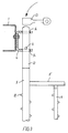
- The invention will be described more in detail in the following with reference to the drawing which is an example and a non-limiting illustration of embodiments of the invention, and wherein
- Figure 1 is a perspective view of a section of the discharge electrodes of an electrostatic precipitator and the suspension device thereof,
- Figure 2 is a blow-up of a detail of Figure 1,
- Figure 3 is a partial sectional sideview of Figure 2, and
- Figure 4 is a perspective view of a detail of Figure 1 wherein two rows of electrodes are served by one and the same impact means.
- In Figure 1, 2 and 3, 1 denotes a U-shaped or angular support or carrier beam mounted horizontally at the top of the precipitator housing. The beam is suspended in insulators 3 by vertical rods 2, said insulators being secured in or on the precipitator housing roof (not shown). On the beam surface facing the housing interior a number of U-shaped
support irons 4 are secured which in each leg have mutually axially locatedholes 14 wherein verticalmetal frame tubes 5 are suspended by means of alocking pin 6. Thevertical frame tubes 5 formed as electrodes with corona discharge bows orprotrusions 10 are at their uppermost ends constituted bymassive rods 12, the upwardly facing end surfaces of which act as anvils for an impact means 13, in the figures in the form of a drop hammer which rotates about a not shown horizontal axis. - The
vertical frame tubes 5 for each precipitator section are mutually connected at their upper and lower ends by horizontal frame tubes 8' and 8'', respectively, and additionally optionally by at least onetransversal frame tube 8 so that the precipitator section frame in the shown embodiment is divided into two or more smaller frames wherein theremaining discharge electrodes 9, 9' are mounted. - In order to obtain maximum torsional rigidity of the construction the
vertical frame tubes 5 may furthermore be connected at their lower ends by means of transversal frame beams 7 which in turn may be connected by cross-braces 11 or diagonal braces. - During rapping or vibration of the electrodes a
rod 12 is hit at its upwardly facing end surface by thedrop hammer 13, cf. Figure 3. The impact produces a downwardly oriented compression wawe in therod 12 and thus in thetube 5. Therod 12 and thetube 5 are suspended in thesupport iron 4 by means of thelocking pin 6 and the support iron makes therefore a resilient movement at the abutment allowing almost unimpeded transfer of the compression wawe downwards to the electrodes thus imparting to the latter a rapping or vibrating movement, thetransversal frame tubes 8', 8 and 8'' being secured to thetube 5 following the movement and with the frame tubes also theelectrodes 9 and 9'. - In precipitators where only moderate rapping is required at least two upwards facing end surfaces of the
frame tubes 5 of two adjacent precipitator sections may be connected by one and thesame anvil 15, cf. Figure 4. This construction requires only a limited number of impact means corresponding to the number of anvils. - The suspension device and the rapping mechanism according to the invention for the discharge electrodes of an electrostatic precipitator represent among other things the following advantages:
- The suspension of the
vertical frame tubes 5 in the U-shapedsupport irons 4 constitutes an torsionally rigid joining which contributes substantially to an increased overall rigidity of the frame construction. - The division of the individual precipitator section frame into two or more smaller frames provides a substantially improved cross-rigidity of the aggregate frame construction.
- Calculations and full-scale measurements have shown that the frame system according to the invention is so rigid that the use of conventional oscillation damping insulators at the lower portion of an electrostatic precipitator may be avoided.
- The frame portions and the electrodes may be designed so as to be of limited length thereby facilitating their packaging and transportation from manufacturer to site of use, and likewise allowing separate assembly of the individual precipitator section frame and subsequently mounting it in its final position in a precipitator housing.
- Due to the resilient suspension of the electrodes in the
support irons 4 the amount of impact energy transferred to the support insulators of the discharge system is reduced.
Claims (3)
- An electrostatic precipitator comprising a suspension device and rapping mechanism for vertically mounted electrodes, preferably rod-shaped, tubular, helical or plate discharge electrodes (5,9), in a high-voltage supplied electrostatic precipitator, and wherein a conductive suspension device comprises at least two U-shaped or angular carrier beams (1) arranged perpendicularly to the precipitator sections or the electrode rows and above and near their upper ends, said carrier beams being suspended in vertical carrier rods (2) which at their upper ends are secured in insulators (3) in the roof of a precipitator housing, the rapping mechanism comprising means (13) mounted on or near the precipitator housing roof in order to produce a vertically acting impact energy towards the upwardly facing ends of the electrodes (5,9) thereby rapping or vibrating the latter, and the vertical support or frame tubes acting as electrodes (5) of each precipitator section being mutually connected by at least one upper and a lower horizontal frame tube (8', 8'') to form vertical frames for the electrode rows, and the remaining vertically mounted rod-shaped or tubular electrodes (9,9') of a precipitator section being arranged between the horizontal frame tubes (8' ,8''), characterized in that a number of U-shaped support irons (4) are secured on the sides of the carrier beams (1) facing the electrode rows and mounted so that the horizontally extending legs of the U are located vertically above eachother, the vertical precipitator support or frame tubes acting as electrodes (5) of each precipitator section or electrode row being suspended in said legs, that the upper portion of the vertical support or frame tubes acting as electrodes (5) are formed as a solid rod (12), vertically movably secured in the individual U-shaped support iron (4) and with its upwardly facing end constituting an abutment or an anvil for the impact means (13) of the rapping mechanism, and that the U-shaped support irons (4) have holes (14) in the legs of the U being arranged vertically above each other for receiving the rod-shaped upper portion (12) of the vertical support or frame tubes so that the suspension of the tubes in the support irons are partly vertically resilient partly torsionally rigid.
- An electrostatic precipitator according to claim 1, characterized in that the rod-shaped portion (12) near its upper end has a hole for a transversal locking pin (6) which upon mounting of the tube in the precipitator housing secures the rod (12) in the U-shaped support iron (4) in such a way that the pin (6) abuts the upwardly facing surface of the lowermost U-leg causing the rod (12), the tube acting as an electrode (5), and the transversal frame tubes (8,8' and 8'') secured to the electrode (5) to carry out an upward and a downward movement through the impact from the impact means whereby the rapping or vibration of the electrodes is effected.
- An electrostatic precipitator according to claims 1 and 2, characterized in that two or more vertical support or frame tubes acting as electrodes (5) are mutually connected at the upwardly facing end surfaces of their rod-shaped portions (12) by a common abutment or a common anvil (15) which, when hit by the impact means (13) of the mechanism, concurrently transfers impact energy to the rods (12) and tubes acting as electrodes (5) connected to said anvil of two or more adjacent precipitator sections or electrode rows.
Applications Claiming Priority (2)
| Application Number | Priority Date | Filing Date | Title |
|---|---|---|---|
| DK1077/92 | 1992-08-28 | ||
| DK199201077A DK172419B1 (en) | 1992-08-28 | 1992-08-28 | Suspension device and banking mechanism for electrodes in an electro filter |
Publications (2)
| Publication Number | Publication Date |
|---|---|
| EP0584881A1 EP0584881A1 (en) | 1994-03-02 |
| EP0584881B1 true EP0584881B1 (en) | 1997-01-08 |
Family
ID=8100746
Family Applications (1)
| Application Number | Title | Priority Date | Filing Date |
|---|---|---|---|
| EP93202477A Expired - Lifetime EP0584881B1 (en) | 1992-08-28 | 1993-08-24 | Electrostatic precipitator |
Country Status (9)
| Country | Link |
|---|---|
| US (1) | US5344481A (en) |
| EP (1) | EP0584881B1 (en) |
| CN (1) | CN1035418C (en) |
| CA (1) | CA2104932A1 (en) |
| DE (1) | DE69307222T2 (en) |
| DK (1) | DK172419B1 (en) |
| ES (1) | ES2098648T3 (en) |
| MX (1) | MX9305202A (en) |
| PL (1) | PL171633B1 (en) |
Families Citing this family (21)
| Publication number | Priority date | Publication date | Assignee | Title |
|---|---|---|---|---|
| DE69516549T2 (en) * | 1994-01-11 | 2000-09-14 | Compania Sevillana De Electricidad, Sevilla | A support element and a vibration device for electrodes of an electrostatic filter |
| US6238459B1 (en) * | 1999-04-23 | 2001-05-29 | The Babcock & Wilcox Company | Ultra-high particulate collection of sub-micron aerosols |
| RU2211093C2 (en) * | 2001-09-10 | 2003-08-27 | Закрытое акционерное общество "Кондор-Эко" | Horizontal multifield electric filter |
| FI121410B (en) * | 2003-06-24 | 2010-11-15 | Alstom Technology Ltd | A method for cleaning an electric filter during a filtration operation and an electric filter |
| US6951580B1 (en) | 2004-04-13 | 2005-10-04 | Nisource Corporate Services Company | Method for minimizing bowing of collector plates in an electrostatic precipitator, and a collector plate-clip combination |
| CA2598187C (en) * | 2005-02-18 | 2015-02-03 | Turbosonic Inc. | Mast electrode design |
| US7438743B2 (en) * | 2006-02-23 | 2008-10-21 | Hamon Research -Cottrell, Inc. | Method of making replacement collecting electrodes for an electrostatic precipitator |
| US7468094B2 (en) * | 2006-02-23 | 2008-12-23 | Hamon Research—Cottrell Inc. | Method of repairing an electrostatic precipitator |
| DE102009060254A1 (en) * | 2009-07-10 | 2011-01-13 | Sms Elex Ag | electrostatic precipitator |
| DE102010021233A1 (en) * | 2009-07-10 | 2011-01-13 | Sms Elex Ag | electrostatic precipitator |
| AT13007U1 (en) * | 2010-06-18 | 2013-03-15 | Scheuch Gmbh | ELECTROFILTER FOR CLEANING DUST-LOADED EXHAUST GASES AND METHOD FOR CLEANING AN ELECTRIC FILTER |
| CN102059045A (en) * | 2010-11-22 | 2011-05-18 | 浙江富春江环保热电股份有限公司 | Venturi atomization compound wet type electrostatic flue gas treatment reactor |
| CA2831174C (en) | 2011-03-28 | 2018-03-20 | Megtec Turbosonic Inc. | Conductive composite material for wesp |
| JP5816810B2 (en) * | 2011-04-22 | 2015-11-18 | パナソニックIpマネジメント株式会社 | Electric dust collector |
| US11027289B2 (en) | 2011-12-09 | 2021-06-08 | Durr Systems Inc. | Wet electrostatic precipitator system components |
| CN103301945A (en) * | 2012-03-17 | 2013-09-18 | 钟方明 | Method for removing ash by closing partial electric field channel and electrostatic dust collector |
| CN105883048B (en) * | 2016-06-08 | 2018-03-30 | 艾尼科环保技术(安徽)有限公司 | A kind of electrostatic precipitator anode arranges packing device |
| CN107029887B (en) * | 2017-05-11 | 2018-09-21 | 艾尼科环保技术(安徽)有限公司 | A kind of Wet-electric duster cathod system device |
| CN110770464B (en) * | 2017-05-31 | 2021-03-23 | Abb瑞士股份有限公司 | Attachment equipment, support structure and method |
| RU193625U1 (en) * | 2019-09-24 | 2019-11-07 | Общество с ограниченной ответственностью "ФИНГО-Комплекс" | Horizontal multi-field electrostatic precipitator |
| CN116060213B (en) * | 2023-01-13 | 2024-07-12 | 浙江菲达环保科技股份有限公司 | Independent vibrating cathode frame and electric dust collector thereof |
Family Cites Families (10)
| Publication number | Priority date | Publication date | Assignee | Title |
|---|---|---|---|---|
| FR1045779A (en) * | 1950-06-09 | 1953-12-01 | Metallgesellschaft Ag | Shaking output electrode element for electrostatic precipitators |
| GB1016905A (en) * | 1962-04-10 | 1966-01-12 | Holmes & Co Ltd W C | Improvements in or relating to electrostatic precipitators |
| FR1431579A (en) * | 1965-04-24 | 1966-03-11 | Metallgesellschaft Ag | Suspension and dust removal device for gas scrubber emission frames |
| DE1557148A1 (en) * | 1966-10-28 | 1970-05-27 | Metallgesellschaft Ag | Plate-shaped spray electrode for electrostatic dust collectors |
| US3729815A (en) * | 1971-01-25 | 1973-05-01 | Koppers Co Inc | Method for installing multiples of dust collector plates |
| SE342990B (en) * | 1971-05-12 | 1972-02-28 | Svenska Flaektfabriken Ab | |
| GB1578378A (en) * | 1978-04-26 | 1980-11-05 | Lodge Cottrell Ltd | Roller bearing for drop rod rapping |
| US4221573A (en) * | 1979-03-06 | 1980-09-09 | Research-Cottrell, Inc. | Electrostatic precipitator rapping mechanism |
| SE452956B (en) * | 1984-11-05 | 1988-01-04 | Flaekt Ab | FOR A MULTIPLE EMISSION ELECTRODES DETERMINED FAST HOLDING DEVICE |
| GB8522312D0 (en) * | 1985-09-09 | 1985-10-16 | Dresser Uk Ltd | Electro-precipitation |
-
1992
- 1992-08-28 DK DK199201077A patent/DK172419B1/en not_active IP Right Cessation
-
1993
- 1993-08-24 EP EP93202477A patent/EP0584881B1/en not_active Expired - Lifetime
- 1993-08-24 ES ES93202477T patent/ES2098648T3/en not_active Expired - Lifetime
- 1993-08-24 DE DE69307222T patent/DE69307222T2/en not_active Expired - Fee Related
- 1993-08-26 CA CA002104932A patent/CA2104932A1/en not_active Abandoned
- 1993-08-26 US US08/112,690 patent/US5344481A/en not_active Expired - Fee Related
- 1993-08-27 PL PL93300225A patent/PL171633B1/en unknown
- 1993-08-27 MX MX9305202A patent/MX9305202A/en not_active IP Right Cessation
- 1993-08-28 CN CN93117043A patent/CN1035418C/en not_active Expired - Fee Related
Also Published As
| Publication number | Publication date |
|---|---|
| MX9305202A (en) | 1994-05-31 |
| DK107792A (en) | 1994-03-01 |
| PL171633B1 (en) | 1997-05-30 |
| PL300225A1 (en) | 1994-03-07 |
| EP0584881A1 (en) | 1994-03-02 |
| CN1035418C (en) | 1997-07-16 |
| US5344481A (en) | 1994-09-06 |
| CA2104932A1 (en) | 1994-03-01 |
| CN1084782A (en) | 1994-04-06 |
| DK107792D0 (en) | 1992-08-28 |
| ES2098648T3 (en) | 1997-05-01 |
| DE69307222D1 (en) | 1997-02-20 |
| DE69307222T2 (en) | 1997-07-17 |
| DK172419B1 (en) | 1998-06-08 |
Similar Documents
| Publication | Publication Date | Title |
|---|---|---|
| US5344481A (en) | Suspension device and rapping mechanism for electrodes in an electrostatic precipitator | |
| US4521229A (en) | Tubular discharge electrode for electrostatic precipitator | |
| EP0584880B1 (en) | Electrostatic precipitator | |
| US3354617A (en) | Corona shield for ionizer wires | |
| US4093431A (en) | Rapping assembly and electrode supports for electrostatic precipitators | |
| JPS61167467A (en) | Apparatus for supporting plural discharge electrodes | |
| US4362538A (en) | Wet electrostatic precipitator having means for dampening the swaying of its discharge electrodes | |
| US3113852A (en) | Cleaning means for channel-shaped dust collecting electrodes | |
| US4277258A (en) | Electrostatic precipitator and discharge electrode therefor | |
| EP0662347B1 (en) | A suspension device and a rapping mechanism for electrodes in an electrostatic precipitator | |
| KR20140068656A (en) | A upper rapper type of electrostatic precipitator | |
| US4747856A (en) | Lower end alignment device for electrostatic precipitator collector electrodes | |
| RU1464352C (en) | Electric filter | |
| RU2277008C1 (en) | Dry horizontal multistage precipitator | |
| RU2251458C1 (en) | Horizontal electric filter | |
| RU2368426C2 (en) | Method for shaking of electric filter electrodes | |
| SU1110487A1 (en) | Electric wave filter provided with rigid system of suspension of corona forming electrodes | |
| RU2626473C1 (en) | Method of two-current regenerating corona electrodes and electrofilter for its implementation | |
| RU2856714C1 (en) | Electrostatic precipitator | |
| US4769049A (en) | Side rapping drag hammer apparatus for electrostatic precipitators | |
| JP2004267957A (en) | Dust collecting plate of electric dust collector | |
| US3350850A (en) | Attachment means for spark electrodes | |
| CA1051359A (en) | Swing hammer rapping system for electrostatic precipitator | |
| US2937711A (en) | Electrode structure for electrostatic precipitator | |
| RU2309004C1 (en) | Dry vertical electrical filter |
Legal Events
| Date | Code | Title | Description |
|---|---|---|---|
| PUAI | Public reference made under article 153(3) epc to a published international application that has entered the european phase |
Free format text: ORIGINAL CODE: 0009012 |
|
| AK | Designated contracting states |
Kind code of ref document: A1 Designated state(s): DE ES FR GB IT SE |
|
| 17P | Request for examination filed |
Effective date: 19940520 |
|
| 17Q | First examination report despatched |
Effective date: 19951031 |
|
| GRAG | Despatch of communication of intention to grant |
Free format text: ORIGINAL CODE: EPIDOS AGRA |
|
| GRAH | Despatch of communication of intention to grant a patent |
Free format text: ORIGINAL CODE: EPIDOS IGRA |
|
| GRAH | Despatch of communication of intention to grant a patent |
Free format text: ORIGINAL CODE: EPIDOS IGRA |
|
| GRAA | (expected) grant |
Free format text: ORIGINAL CODE: 0009210 |
|
| AK | Designated contracting states |
Kind code of ref document: B1 Designated state(s): DE ES FR GB IT SE |
|
| REF | Corresponds to: |
Ref document number: 69307222 Country of ref document: DE Date of ref document: 19970220 |
|
| ITF | It: translation for a ep patent filed | ||
| ET | Fr: translation filed | ||
| REG | Reference to a national code |
Ref country code: ES Ref legal event code: FG2A Ref document number: 2098648 Country of ref document: ES Kind code of ref document: T3 |
|
| PLBE | No opposition filed within time limit |
Free format text: ORIGINAL CODE: 0009261 |
|
| 26N | No opposition filed | ||
| PGFP | Annual fee paid to national office [announced via postgrant information from national office to epo] |
Ref country code: SE Payment date: 19990804 Year of fee payment: 7 |
|
| PGFP | Annual fee paid to national office [announced via postgrant information from national office to epo] |
Ref country code: FR Payment date: 20000811 Year of fee payment: 8 |
|
| PGFP | Annual fee paid to national office [announced via postgrant information from national office to epo] |
Ref country code: DE Payment date: 20000814 Year of fee payment: 8 |
|
| PGFP | Annual fee paid to national office [announced via postgrant information from national office to epo] |
Ref country code: GB Payment date: 20000823 Year of fee payment: 8 |
|
| PG25 | Lapsed in a contracting state [announced via postgrant information from national office to epo] |
Ref country code: SE Free format text: LAPSE BECAUSE OF NON-PAYMENT OF DUE FEES Effective date: 20000825 |
|
| PGFP | Annual fee paid to national office [announced via postgrant information from national office to epo] |
Ref country code: ES Payment date: 20000830 Year of fee payment: 8 |
|
| EUG | Se: european patent has lapsed |
Ref document number: 93202477.1 |
|
| PG25 | Lapsed in a contracting state [announced via postgrant information from national office to epo] |
Ref country code: GB Free format text: LAPSE BECAUSE OF NON-PAYMENT OF DUE FEES Effective date: 20010824 |
|
| PG25 | Lapsed in a contracting state [announced via postgrant information from national office to epo] |
Ref country code: ES Free format text: LAPSE BECAUSE OF NON-PAYMENT OF DUE FEES Effective date: 20010825 |
|
| GBPC | Gb: european patent ceased through non-payment of renewal fee |
Effective date: 20010824 |
|
| PG25 | Lapsed in a contracting state [announced via postgrant information from national office to epo] |
Ref country code: FR Free format text: LAPSE BECAUSE OF NON-PAYMENT OF DUE FEES Effective date: 20020430 |
|
| PG25 | Lapsed in a contracting state [announced via postgrant information from national office to epo] |
Ref country code: DE Free format text: LAPSE BECAUSE OF NON-PAYMENT OF DUE FEES Effective date: 20020501 |
|
| REG | Reference to a national code |
Ref country code: FR Ref legal event code: ST |
|
| REG | Reference to a national code |
Ref country code: ES Ref legal event code: FD2A Effective date: 20020911 |
|
| PG25 | Lapsed in a contracting state [announced via postgrant information from national office to epo] |
Ref country code: IT Free format text: LAPSE BECAUSE OF NON-PAYMENT OF DUE FEES;WARNING: LAPSES OF ITALIAN PATENTS WITH EFFECTIVE DATE BEFORE 2007 MAY HAVE OCCURRED AT ANY TIME BEFORE 2007. THE CORRECT EFFECTIVE DATE MAY BE DIFFERENT FROM THE ONE RECORDED. Effective date: 20050824 |