EP0584494A1 - Electropneumatic valve sub-assembly - Google Patents
Electropneumatic valve sub-assembly Download PDFInfo
- Publication number
- EP0584494A1 EP0584494A1 EP93110630A EP93110630A EP0584494A1 EP 0584494 A1 EP0584494 A1 EP 0584494A1 EP 93110630 A EP93110630 A EP 93110630A EP 93110630 A EP93110630 A EP 93110630A EP 0584494 A1 EP0584494 A1 EP 0584494A1
- Authority
- EP
- European Patent Office
- Prior art keywords
- valve
- plate
- adapter plate
- connection
- valve assembly
- Prior art date
- Legal status (The legal status is an assumption and is not a legal conclusion. Google has not performed a legal analysis and makes no representation as to the accuracy of the status listed.)
- Granted
Links
Images

Classifications
-
- F—MECHANICAL ENGINEERING; LIGHTING; HEATING; WEAPONS; BLASTING
- F15—FLUID-PRESSURE ACTUATORS; HYDRAULICS OR PNEUMATICS IN GENERAL
- F15B—SYSTEMS ACTING BY MEANS OF FLUIDS IN GENERAL; FLUID-PRESSURE ACTUATORS, e.g. SERVOMOTORS; DETAILS OF FLUID-PRESSURE SYSTEMS, NOT OTHERWISE PROVIDED FOR
- F15B13/00—Details of servomotor systems ; Valves for servomotor systems
- F15B13/02—Fluid distribution or supply devices characterised by their adaptation to the control of servomotors
- F15B13/06—Fluid distribution or supply devices characterised by their adaptation to the control of servomotors for use with two or more servomotors
- F15B13/08—Assemblies of units, each for the control of a single servomotor only
- F15B13/0803—Modular units
- F15B13/0832—Modular valves
-
- F—MECHANICAL ENGINEERING; LIGHTING; HEATING; WEAPONS; BLASTING
- F15—FLUID-PRESSURE ACTUATORS; HYDRAULICS OR PNEUMATICS IN GENERAL
- F15B—SYSTEMS ACTING BY MEANS OF FLUIDS IN GENERAL; FLUID-PRESSURE ACTUATORS, e.g. SERVOMOTORS; DETAILS OF FLUID-PRESSURE SYSTEMS, NOT OTHERWISE PROVIDED FOR
- F15B13/00—Details of servomotor systems ; Valves for servomotor systems
- F15B13/02—Fluid distribution or supply devices characterised by their adaptation to the control of servomotors
- F15B13/06—Fluid distribution or supply devices characterised by their adaptation to the control of servomotors for use with two or more servomotors
- F15B13/08—Assemblies of units, each for the control of a single servomotor only
- F15B13/0803—Modular units
- F15B13/0807—Manifolds
- F15B13/0814—Monoblock manifolds
-
- F—MECHANICAL ENGINEERING; LIGHTING; HEATING; WEAPONS; BLASTING
- F15—FLUID-PRESSURE ACTUATORS; HYDRAULICS OR PNEUMATICS IN GENERAL
- F15B—SYSTEMS ACTING BY MEANS OF FLUIDS IN GENERAL; FLUID-PRESSURE ACTUATORS, e.g. SERVOMOTORS; DETAILS OF FLUID-PRESSURE SYSTEMS, NOT OTHERWISE PROVIDED FOR
- F15B13/00—Details of servomotor systems ; Valves for servomotor systems
- F15B13/02—Fluid distribution or supply devices characterised by their adaptation to the control of servomotors
- F15B13/06—Fluid distribution or supply devices characterised by their adaptation to the control of servomotors for use with two or more servomotors
- F15B13/08—Assemblies of units, each for the control of a single servomotor only
- F15B13/0803—Modular units
- F15B13/0846—Electrical details
- F15B13/0857—Electrical connecting means, e.g. plugs, sockets
-
- F—MECHANICAL ENGINEERING; LIGHTING; HEATING; WEAPONS; BLASTING
- F15—FLUID-PRESSURE ACTUATORS; HYDRAULICS OR PNEUMATICS IN GENERAL
- F15B—SYSTEMS ACTING BY MEANS OF FLUIDS IN GENERAL; FLUID-PRESSURE ACTUATORS, e.g. SERVOMOTORS; DETAILS OF FLUID-PRESSURE SYSTEMS, NOT OTHERWISE PROVIDED FOR
- F15B13/00—Details of servomotor systems ; Valves for servomotor systems
- F15B13/02—Fluid distribution or supply devices characterised by their adaptation to the control of servomotors
- F15B13/06—Fluid distribution or supply devices characterised by their adaptation to the control of servomotors for use with two or more servomotors
- F15B13/08—Assemblies of units, each for the control of a single servomotor only
- F15B13/0803—Modular units
- F15B13/0875—Channels for electrical components, e.g. for cables or sensors
-
- F—MECHANICAL ENGINEERING; LIGHTING; HEATING; WEAPONS; BLASTING
- F15—FLUID-PRESSURE ACTUATORS; HYDRAULICS OR PNEUMATICS IN GENERAL
- F15B—SYSTEMS ACTING BY MEANS OF FLUIDS IN GENERAL; FLUID-PRESSURE ACTUATORS, e.g. SERVOMOTORS; DETAILS OF FLUID-PRESSURE SYSTEMS, NOT OTHERWISE PROVIDED FOR
- F15B13/00—Details of servomotor systems ; Valves for servomotor systems
- F15B13/02—Fluid distribution or supply devices characterised by their adaptation to the control of servomotors
- F15B13/06—Fluid distribution or supply devices characterised by their adaptation to the control of servomotors for use with two or more servomotors
- F15B13/08—Assemblies of units, each for the control of a single servomotor only
- F15B13/0803—Modular units
- F15B13/0878—Assembly of modular units
- F15B13/0896—Assembly of modular units using different types or sizes of valves
Definitions
- the invention relates to an electropneumatic valve assembly according to the type specified in the preamble of claim 1.
- Such an electropneumatic valve assembly is already known from EP 0 413 960 A1, in which a plurality of valve arrangements are arranged in parallel next to one another on a base plate through which pressure medium channels pass.
- Each valve arrangement consists of a main valve and two electromagnetic control units arranged on the front, which are mounted together on the base plate via an adapter plate.
- the adapter plate in which there are flow channels for the pressure medium, electrical lines for the electromagnetic control units are laid and it has two flexible intermediate areas with which the adapter plate can compensate for large tolerance ranges.
- the base plate traversed by the pressure medium channels is formed in one piece and its length is limited to a certain number of valve positions, so that the number of possible control functions is also limited. It is therefore not possible to achieve an optimal design in certain applications, e.g. if a different number of ways would be required instead of the 5-way valve series.
- an electropneumatic valve assembly is known from DE 40 04 834 A1, in which an intermediate adapter plate is arranged between a base plate and a main valve. In addition to pressure medium-carrying working channels and fluidic control channels, this adapter plate also receives electrical lines which connect the electromagnetic control units to an electrical connection of the base plate.
- the electromagnetic control units are integrated in fluidic pilot valves, which are flanged to the adapter plate at the end.
- the disadvantage of this valve assembly is that the adapter plate is complex to build and is only suitable for the same valve series.
- a base plate with several valve positions is missing here.
- the main valve of the valve assembly is actuated fluidically, the control valves flanged on the end face of the adapter plate merely taking on pilot control functions. The use of different valve series is also not possible here.
- the electropneumatic valve assembly according to the invention for mounting on a base plate with the characterizing features of the main claim has the advantage that different valve series can be used together on the same base plate, so that a mixed valve series is created.
- connection plate With the help of the connection plate, one or two 3/2-solenoid valves can be arranged on a valve position on the base plate, so that installation space and costs are saved and more control functions can be accommodated in the same existing installation space. It is particularly favorable if 5-way valves and 3-way valves are mixed in the valve block. The advantages of the flexible adapter plate can be retained without restriction.
- FIG. 1 shows a partial longitudinal section through an electropneumatic valve assembly according to the invention attached to a base plate, part of which is shown in section
- FIG. 2 shows a plan view of the base plate with the attached electropneumatic valve assembly according to FIG. 1
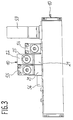
- FIG. 3 shows a side view of the base plate with the assembled Valve assemblies according to arrow direction A in Figure 2.
- an electropneumatic valve assembly 10 is shown partially in longitudinal section, which is attached to a valve location on a base plate 11.
- a base plate 11 In the base plate 11, three parallel longitudinal channels are provided in the usual way, of which a first longitudinal duct 12 for supplying pressure medium to the supply air and the second or third longitudinal duct 13, 14 are connected to the exhaust air.
- Cross channels 15, 16 and 17 each lead from these longitudinal channels 12, 13, 14 into a connecting surface 18 of the base plate 11 and form a valve location 19 there.
- the valve assembly 10 arranged on the valve location 19 consists essentially of a multi-unit adapter plate 21 resting on the connection surface 18, a cuboid connection plate 22 fastened to the adapter plate 21, and the two 3/2-solenoid valves fastened to the end faces of the connection plate 22 23 or 24 and their associated electromagnetic control units, which are designed here as magnets 25 or 26.
- the connection plate can be made of metal or plastic.
- the adapter plate 21 has a design known per se, in which there are three through bores 28, 29, 31 in a base part 27, which communicate with transverse channels 15, 16 and 17 in the base plate 11.
- the base part 27 merges at its two outer ends via an elastic region 32 into an external connection part 33 or 34.
- the two connection parts 33, 34 are connected to one another via electrical lines and have suitable plug connections in a manner known per se, so that they can each be connected to the electrical plug contacts of the magnets 25 and 26, respectively.
- a screw connection 35 ensures sufficient mechanical fastening between the magnet and the associated connecting part.
- 33 plug contacts 36 are formed in the region of the first connecting part, with which the adapter plate 21 can be connected to an electrical connector strip 37 in the base plate 10.
- the magnets 25, 26 are screwed in the usual way to the solenoid valves 23 and 24, which in turn are fastened to the connecting plate 22 in a manner known per se.
- Commercially available components can be used for the magnets 25, 26, in which a longitudinally movable armature is used to actuate a control element in the solenoid valve 23 or 24.
- Commercially available components can also be used with the solenoid valves 23, 24, each of which has a 3-way, 2-position function, so that they can either connect a work connection to the supply air or vent it.
- connection plate 22 is adapted to the given conditions by adaptation.
- the cuboidal connection plate 22 has two opposite end faces 38, 39, into each of which two pressure medium channels 41, 42 and 43, 44 open.
- the solenoid valve 23 attached to the first end face 38 controls the connection between the two pressure medium channels 41, 42, while the second solenoid valve 24 attached to the second end face 39 controls the connection between the two channels 43 and 44.
- the connection plate 22 has on its upper connection surface 45 two consumer connections 46, 47, of which the first 46 has a connection to the pressure medium channel 41, while the second consumer connection 47 is connected to the channel 43.
- the two other pressure medium channels 42 and 44 lead to an inlet channel 48 which is designed as a blind hole and which is open to a flange surface 49 formed at the bottom of the connection plate 22 and has a connection to the through hole 28 in the adapter plate 21.
- the adapter plate 21 has a blind hole 51 in the flange surface 49, into which a pin 52 engages in order to center the connection plate 22 relative to the adapter plate 21 and sits in the third through hole 31 of the adapter plate 21.
- the connection plate 22 is further delimited by two mutually parallel side walls 53, so that the thickness of the connection plate 22 is adapted to the width of the adapter plate 21 and thus to the available space at the valve location 19.
- FIG. 2 shows a top view of base plate 11 with valve assemblies mounted on it
- FIG. 3 shows a side view of base plate 11 in the direction of arrow A according to FIG. 2.
- the base plate 11 has a total of 6 valve positions, of which the second valve position 19 is occupied by the electropneumatic valve assembly 10.
- a 5/2-way valve 54 which is designed as a changeover valve, is mounted on a first valve position of the base plate 11, while a 5/3-way valve 55 is arranged on the third valve position.
- the fourth valve position of the base plate 11 is covered by a blind plate 56, while the fifth and sixth valve positions 57 and 58 are shown as not occupied.
- FIG. 2 in connection with FIG.
- valve assembly 10 and the 5/3-way valve 55 are each mounted via adapter plates 21, which are identical to one another.
- the 5/2-way valve 54 can be attached directly to the base plate 11 without an additional adapter plate.
- the two directional control valves 54 and 55 are also connected to the electrical plug connector 37, which in turn is in an electrically conductive connection with the central plug 59 in a manner known per se.
- the mode of operation of the electropneumatic valve assembly 10 is explained as follows, the basic function of such valve batteries in which a plurality of directional valves or valve assemblies are arranged on a base area 11 being assumed to be known per se.
- Mixed valve arrangements can be realized with the electropneumatic valve assembly 10 on a common base plate 11.
- directional valves 54, 55 of the same valve series equipped, namely with 5-way valves 19 valves of another series can be accommodated in the second valve position, namely 3-way valves.
- a mixed valve arrangement can therefore be achieved with which certain control functions can be better performed.
- each solenoid valve 23 or 24 can connect its associated consumer connection 46 or 47 either to the inlet channel 48 or to relieve the outside air. The ventilation takes place via an outlet, not shown, in the solenoid valves 23 or 24 to the outside air.
- valve assembly 10 can be mounted inexpensively, since the connection plate 22 can be attached to the adapter plate 27 in a simple manner and the assembly of the commercially available solenoid valves 23, 24 or the magnets 25 or 26 is carried out as usual.
- the electropneumatic valve assembly 10 can be arranged at any valve location on the base plate 11. Although it is particularly advantageous to install two 3/2-way solenoid valves on the connection plate 22, one of the two solenoid valves can also be omitted if necessary and thus only one control function can be used. Instead of the 5-way and 3-way valves shown, other valve series can also be mixed in a corresponding manner.
Abstract
Description
Die Erfindung geht aus von einer elektropneumatischen Ventilbaugruppe nach der im Oberbegriff des Anspruchs 1 näher angegebenen Gattung.The invention relates to an electropneumatic valve assembly according to the type specified in the preamble of claim 1.
Es ist schon eine solche elektropneumatische Ventilbaugruppe aus der EP 0 413 960 A1 bekannt, bei der auf einer von Druckmittelkanälen durchzogenen Grundplatte mehrere Ventilanordnungen parallel nebeneinander angeordnet sind. Dabei besteht jede Ventilanordnung aus einem Hauptventil und zwei stirnseitig angeordneten, elektromagnetischen Ansteuereinheiten, die zusammen über eine Adapterplatte auf der Grundplatte angebaut sind. In der Adapterplatte, in der Durchlaufkanäle für das Druckmittel liegen, sind elektrische Leitungen für die elektromagnetischen Ansteuereinheiten verlegt und sie weist zwei flexible Zwischenbereiche auf, mit denen die Adapterplatte große Toleranzbereiche ausgleichen kann. Obwohl diese elektropneumatische Ventilbaugruppe in vielen Fällen vorteilhaft einsetzbar ist, tritt bei manchen Anwendungsfällen der Nachteil auf, daß hier nur gleiche Ventilbaureihen an der Grundplatte anschließbar sind. Dabei handelt es sich bei den Hauptventilen in der Regel um 5/2- oder 5/3- Wege-Ventile in einer Bauweise mit Rohranschlüssen.Such an electropneumatic valve assembly is already known from EP 0 413 960 A1, in which a plurality of valve arrangements are arranged in parallel next to one another on a base plate through which pressure medium channels pass. Each valve arrangement consists of a main valve and two electromagnetic control units arranged on the front, which are mounted together on the base plate via an adapter plate. In the adapter plate, in which there are flow channels for the pressure medium, electrical lines for the electromagnetic control units are laid and it has two flexible intermediate areas with which the adapter plate can compensate for large tolerance ranges. Although this electropneumatic valve assembly can be used advantageously in many cases, the disadvantage occurs in some applications that only the same valve series can be connected to the base plate. The main valves are usually 5/2 or 5/3 way valves in a design with pipe connections.
Die von den Druckmittelkanälen durchzogene Grundplatte ist einstückig ausgebildet und dabei in ihrer Länge auf eine bestimmte Anzahl von Ventilplätzen beschränkt, so daß damit auch die Anzahl der möglichen Steuerfunktionen begrenzt wird. Es kann daher in bestimmten Anwendungsfällen keine optimale Auslegung erzielt werden, wenn z.B. anstelle der Ventilbaureihe mit 5 Wegen eine andere Anzahl von Wegen erforderlich wäre.The base plate traversed by the pressure medium channels is formed in one piece and its length is limited to a certain number of valve positions, so that the number of possible control functions is also limited. It is therefore not possible to achieve an optimal design in certain applications, e.g. if a different number of ways would be required instead of the 5-way valve series.
Ferner ist aus der DE 40 04 834 A1 eine elektropneumatische Ventilbaugruppe bekannt, bei der zwischen einer Basisplatte und einem Hauptventil eine dazwischenliegende Adapterplatte angeordnet ist. Diese Adapterplatte nimmt neben druckmittelführenden Arbeitskanälen und fluidischen Steuerkanälen auch elektrische Leitungen auf, welche die elektromagnetischen Ansteuereinheiten mit einem elektrischen Anschluß der Grundplatte verbinden. Bei dieser Ventilbaugruppe sind die elektromagnetischen Ansteuereinheiten in fluidischen Vorsteuerventilen integriert, welche stirnseitig an die Adapterplatte angeflanscht sind. Von Nachteil bei dieser Ventilbaugruppe ist, daß hier die Adapterplatte aufwendig baut und auch nur für gleiche Ventilbaureihen geeignet ist. Zudem fehlt hier eine Grundplatte mit mehreren Ventilplätzen. Außerdem wird das Hauptventil der Ventilbaugruppe fluidisch betätigt, wobei die stirnseitig an der Adapterplatte angeflanschten Steuerventile lediglich Vorsteuerfunktionen übernehmen. Die Verwendung unterschiedlicher Ventilbaureihen ist hier ebenfalls nicht möglich.Furthermore, an electropneumatic valve assembly is known from DE 40 04 834 A1, in which an intermediate adapter plate is arranged between a base plate and a main valve. In addition to pressure medium-carrying working channels and fluidic control channels, this adapter plate also receives electrical lines which connect the electromagnetic control units to an electrical connection of the base plate. In this valve assembly, the electromagnetic control units are integrated in fluidic pilot valves, which are flanged to the adapter plate at the end. The disadvantage of this valve assembly is that the adapter plate is complex to build and is only suitable for the same valve series. In addition, a base plate with several valve positions is missing here. In addition, the main valve of the valve assembly is actuated fluidically, the control valves flanged on the end face of the adapter plate merely taking on pilot control functions. The use of different valve series is also not possible here.
Die erfindungsgemäße elektropneumatische Ventilbaugruppe zum Anbau an eine Grundplatte mit den kennzeichnenden Merkmalen des Hauptanspruchs hat demgegenüber den Vorteil, daß auf der gleichen Grundplatte unterschiedliche Ventilbaureihen gemeinsam anwendbar sind, so daß eine gemischte Ventilbaureihe entsteht.The electropneumatic valve assembly according to the invention for mounting on a base plate with the characterizing features of the main claim has the advantage that different valve series can be used together on the same base plate, so that a mixed valve series is created.
Mit Hilfe der Anschlußplatte lassen sich dabei auf einem Ventilplatz der Grundplatte ein oder zwei 3/2- Magnet-Ventile anordnen, so daß Bauraum und Kosten gespart werden und auf dem gleichen vorhandenen Bauraum mehr Steuerfunktionen untergebracht werden können. Besonders günstig ist es, wenn in dem Ventilblock 5-Wege-Ventile und 3-Wege-Ventile gemischt angeordnet werden. Die Vorteile der flexiblen Adapterplatte lassen sich dabei uneingeschränkt beibehalten.With the help of the connection plate, one or two 3/2-solenoid valves can be arranged on a valve position on the base plate, so that installation space and costs are saved and more control functions can be accommodated in the same existing installation space. It is particularly favorable if 5-way valves and 3-way valves are mixed in the valve block. The advantages of the flexible adapter plate can be retained without restriction.
Durch die in den Unteransprüchen aufgeführten Maßnahmen sind vorteilhafte Weiterbildungen und Verbesserungen der im Hauptanspruch angegebenen elektropneumatischen Ventilbaugruppe möglich. Dabei begünstigen sie eine besonders einfache, platzsparende und kostengünstige Lösung.The measures listed in the subclaims permit advantageous developments and improvements of the electropneumatic valve assembly specified in the main claim. They favor a particularly simple, space-saving and inexpensive solution.
Ein Ausführungsbeispiel der Erfindung ist in der Zeichnung dargestellt und in der nachfolgenden Beschreibung näher erläutert.An embodiment of the invention is shown in the drawing and explained in more detail in the following description.
Es zeigen Figur 1 einen teilweisen Längsschnitt durch eine erfindungsgemäße elektropneumatische Ventilbaugruppe angebaut an eine Grundplatte, von der ein Teil im Schnitt dargestellt ist, Figur 2 eine Draufsicht auf die Grundplatte mit der angebauten elektropneumatischen Ventilbaugruppe nach Figur 1 und Figur 3 eine Seitenansicht der Grundplatte mit aufgebauten Ventilbaugruppen nach Pfeilrichtung A in Figur 2.1 shows a partial longitudinal section through an electropneumatic valve assembly according to the invention attached to a base plate, part of which is shown in section, FIG. 2 shows a plan view of the base plate with the attached electropneumatic valve assembly according to FIG. 1, and FIG. 3 shows a side view of the base plate with the assembled Valve assemblies according to arrow direction A in Figure 2.
In der Figur 1 ist eine elektropneumatische Ventilbaugruppe 10 teilweise im Längsschnitt dargestellt, die auf einem Ventilplatz einer Grundplatte 11 befestigt ist. In der Grundplatte 11 sind in üblicher Weise drei parallel zueinander verlaufende Längskanäle vorgesehen, von denen ein erster Längskanal 12 zur Druckmittelversorgung an die Zuluft und der zweite bzw. dritte Längskanal 13, 14 an die Abluft angeschlossen sind. Von diesen Längskanälen 12, 13, 14 führen jeweils Querkanäle 15, 16, bzw. 17 in eine Anschlußfläche 18 der Grundplatte 11 und bilden dort einen Ventilplatz 19.In FIG. 1, an
Die auf dem Ventilplatz 19 angeordnete Ventilbaugruppe 10 besteht im wesentlichen aus einer an der Anschlußfläche 18 aufliegenden, mehrgliedrigen Adapterplatte 21, einer auf der Adapterplatte 21 befestigten, quaderförmigen Anschlußplatte 22, den beiden an den Stirnseiten der Anschlußplatte 22 befestigten 3/2-Magnet-Ventilen 23 bzw. 24 und ihren zugeordneten elektromagnetischen Ansteuereinheiten, die hier als Magnete 25 bzw. 26 ausgebildet sind. Die Anschlußplatte kann aus Metall oder Kunststoff hergestellt werden.The
Wie Figur 1 ferner zeigt, weist die Adapterplatte 21 eine an sich bekannte Bauart auf, bei der in einem Basisteil 27 drei Durchgangsbohrungen 28, 29, 31 liegen, welche mit Querkanälen 15, 16 bzw. 17 in der Grundplatte 11 kommunizieren. Das Basisteil 27 geht an seinen beiden äußeren Enden jeweils über einen elastischen Bereich 32 in ein außenliegendes Anschlußteil 33 bzw. 34 über. Die beiden Anschlußteile 33, 34 stehen über elektrische Leitungen miteinander in Verbindung und weisen in an sich bekannter Weise geeignete Steckverbindungen auf, so daß sie jeweils an die elektrischen Steckkontakte der Magnete 25 bzw. 26 anschließbar sind. Eine Schraubverbindung 35 sorgt für eine ausreichende mechanische Befestigung zwischen Magnet und zugeordnetem Anschlußteil. An der Unterseite der Adapterplatte 21 sind im Bereich des ersten Anschlußteils 33 Steckkontakte 36 ausgebildet, mit denen die Adapterplatte 21 an eine elektrische Steckerleiste 37 in der Grundplatte 10 anschließbar ist.As FIG. 1 also shows, the
Die Magnete 25, 26 sind in üblicher Weise an den Magnetventilen 23 bzw. 24 festgeschraubt, die ihrerseits in an sich bekannter Weise an der Anschlußplatte 22 befestigt sind. Bei den Magneten 25, 26 können handelsübliche Bauelemente verwendet werden, bei denen ein längsbeweglicher Anker zur Betätigung eines Steuergliedes in dem Magnetventil 23 bzw. 24 herangezogen wird. Auch bei den Magnetventilen 23, 24 lassen sich handelsübliche Bauelemente verwenden, die jeweils eine 3-Wege-2-Stellungsfunktion aufweisen, so daß sie wahlweise einen Arbeitsanschluß mit der Zuluft verbinden oder entlüften können.The
Damit in der elektropneumatischen Ventilbaugruppe 10 die bereits vorhandenen Bauelemente wie Adapterplatte 21, Magnetventile 23, 24 und Magnete 25, 26 verwendet werden können, ist die Anschlußplatte 22 durch Adaption an die gegebenen Verhältnisse angepaßt. Die quaderförmige Anschlußplatte 22 weist zwei entgegengesetzt liegende Stirnseiten 38, 39 auf, in die jeweils zwei Druckmittelkanäle 41, 42 bzw. 43, 44 münden. Das an der ersten Stirnseite 38 befestigte Magnetventil 23 steuert die Verbindung zwischen den beiden Druckmittelkanälen 41, 42, während das an der zweiten Stirnseite 39 angebaute zweite Magnetventil 24 die Verbindung zwischen den beiden Kanälen 43 und 44 steuert. Die Anschlußplatte 22 weist an ihrer oberen Anschlußfläche 45 zwei Verbraucheranschlüsse 46, 47 auf, von denen der erste 46 mit dem Druckmittelkanal 41 Verbindung hat, während der zweite Verbraucheranschluß 47 mit dem Kanal 43 verbunden ist. Die beiden anderen Druckmittelkanäle 42 und 44 führen zu einem als Sacklochbohrung ausgebildeten Zulaufkanal 48, welcher zu einer unten an der Anschlußplatte 22 ausgebildeten Flanschfläche 49 hin offen ist und mit der Durchgangsbohrung 28 in der Adapterplatte 21 Verbindung hat. Ferner weist die Adapterplatte 21 in der Flanschfläche 49 eine Sacklochbohrung 51 auf, in die zur Zentrierung der Anschlußplatte 22 relativ zur Adapterplatte 21 ein Stift 52 greift, der in der dritten Durchgangsbohrung 31 der Adapterplatte 21 sitzt. Die Anschlußplatte 22 wird ferner von zwei zueinander parallelen Seitenwänden 53 begrenzt, so daß die Dicke der Anschlußplatte 22 der Breite der Adapterplatte 21 und damit dem verfügbaren Raum am Ventilplatz 19 angepaßt ist.So that the existing components such as
Die Figur 2 zeigt eine Draufsicht auf die Grundplatte 11 mit aufmontierten Ventilbaugruppen, während die Figur 3 eine Seitenansicht der Grundplatte 11 in Pfeilrichtung A nach Figur 2 zeigt. Die Grundplatte 11 hat insgesamt 6 Ventilplätze, von denen der zweite Ventilplatz 19 mit der elektropneumatischen Ventilbaugruppe 10 besetzt ist. Auf einem ersten Ventilplatz der Grundplatte 11 ist ein 5/2-Wege-Ventil 54 montiert, das als Umschaltventil ausgebildet ist, während auf dem dritten Ventilplatz ein 5/3-Wege-Ventil 55 angeordnet ist. Der vierte Ventilplatz der Grundplatte 11 ist von einer Blindplatte 56 abgedeckt, während der fünfte und sechste Ventilplatz 57 bzw. 58 als nicht besetzt dargestellt sind. Wie aus Figur 2 in Verbindung mit Figur 3 näher hervorgeht, sind die Ventilbaugruppe 10 sowie das 5/3-Wege-Ventil 55 jeweils über Adapterplatten 21 montiert, die untereinander gleich ausgeführt sind. Am ersten Ventilplatz kann das 5/2-Wege-Ventil 54 ohne zusätzliche Adapterplatte unmittelbar auf der Grundplatte 11 befestigt werden. Neben der Ventilanordnung 10 sind auch die beiden Wegeventile 54 und 55 an die elektrische Steckerleiste 37 angeschlossen die ihrerseits in an sich bekannter Weise mit dem Zentralstecker 59 in elektrisch leitender Verbindung steht.FIG. 2 shows a top view of
Die Wirkungsweise der elektropneumatischen Ventilbaugruppe 10 wird wie folgt erläutert, wobei die grundsätzliche Funktion solcher Ventilbatterien, bei denen auf einer Grundfläche 11 mehrere Wegeventile bzw. Ventilbaugruppen angeordnet sind, als an sich bekannt vorausgesetzt wird. Mit der elektropneumatischen Ventilbaugruppe 10 können auf einer gemeinsamen Grundplatte 11 gemischte Ventilanordnungen realisiert werden. Während der erste und dritte Ventilplatz der Grundplatte 11 mit Wegeventilen 54, 55 der gleichen Ventilbaureihe bestückt sind, nämlich mit 5-Wege-Ventilen, lassen sich auf dem zweiten Ventilplatz 19 Ventile einer anderen Baureihe unterbringen, nämlich 3-Wege-Ventile. Es kann daher eine gemischte Ventilanordnung erzielt werden, mit der sich bestimmte Steuerfunktionen besser erfüllen lassen. Durch die Anordnung zweier 3/2-Magnetventile auf dem gleichen Ventilplatz 19 der Grundplatte 11 lassen sich Bauraum und Kosten einsparen und der Funktionsinhalt des Ventilblocks kann ausgehend von einer gleichen Grundplatte erhöht werden. Durch die spezielle Ausbildung der Anschlußplatte 22 wird lediglich die Funktion der ersten Durchgangsbohrung 28 für die Zuluft ausgenutzt, während die Funktion der anderen Durchgangsbohrungen 29, 31 für die Abluft nicht benutzt wird. Jedes Magnetventil 23 bzw. 24 kann seinen zugeordneten Verbraucheranschluß 46 bzw. 47 wahlweise mit dem Zulaufkanal 48 verbinden oder zur Außenluft entlasten. Die Entlüftung erfolgt dabei über einen nicht näher gezeichneten Ausgang in den Magnetventilen 23 bzw. 24 zur Außenluft.The mode of operation of the
Die Ventilbaugruppe 10 läßt sich günstig montieren, da die Anschlußplatte 22 in einfacher Weise an die Adapterplatte 27 anbaubar ist und die Montage der handelsüblichen Magnetventile 23, 24 bzw. der Magnete 25 bzw. 26 wie üblich erfolgt.The
Selbstverständlich sind an den gezeigten Ausführungsformen Änderungen möglich, ohne vom Gedanken der Erfindung abzuweichen. Die elektropneumatische Ventilbaugruppe 10 kann an jedem beliebigen Ventilplatz der Grundplatte 11 angeordnet werden. Obwohl es besonders vorteilhaft ist, an der Anschlußplatte 22 zwei 3/2-Magnetventile anzubauen, kann bei Bedarf auch eines der beiden Magnetventile entfallen und somit nur eine Steuerfunktion benutzt werden. Anstelle der gezeigten 5-Wege- und 3-Wege-Ventile können auch andere Ventilbaureihen in entsprechender Weise gemischt werden.Of course, changes are possible to the embodiments shown without departing from the spirit of the invention. The
Claims (6)
Applications Claiming Priority (2)
| Application Number | Priority Date | Filing Date | Title |
|---|---|---|---|
| DE4226539 | 1992-08-11 | ||
| DE4226539A DE4226539A1 (en) | 1992-08-11 | 1992-08-11 | Electropneumatic valve assembly |
Publications (2)
| Publication Number | Publication Date |
|---|---|
| EP0584494A1 true EP0584494A1 (en) | 1994-03-02 |
| EP0584494B1 EP0584494B1 (en) | 1997-01-22 |
Family
ID=6465297
Family Applications (1)
| Application Number | Title | Priority Date | Filing Date |
|---|---|---|---|
| EP93110630A Expired - Lifetime EP0584494B1 (en) | 1992-08-11 | 1993-07-03 | Electropneumatic valve sub-assembly |
Country Status (3)
| Country | Link |
|---|---|
| EP (1) | EP0584494B1 (en) |
| DE (2) | DE4226539A1 (en) |
| ES (1) | ES2096147T3 (en) |
Cited By (4)
| Publication number | Priority date | Publication date | Assignee | Title |
|---|---|---|---|---|
| EP0692638A1 (en) * | 1994-07-13 | 1996-01-17 | UNIVER S.p.A. | Device for wiring solenoid valves to air-distribution subbases |
| EP0754866A2 (en) * | 1995-07-20 | 1997-01-22 | Festo KG | Valve arrangement |
| DE102006056089A1 (en) * | 2006-11-28 | 2008-05-29 | Festo Ag & Co. | valve means |
| WO2008138371A1 (en) * | 2007-05-12 | 2008-11-20 | Festo Ag & Co. Kg | Modular valve arrangement for different throughflow categories |
Families Citing this family (3)
| Publication number | Priority date | Publication date | Assignee | Title |
|---|---|---|---|---|
| DE4416285A1 (en) | 1994-05-07 | 1995-11-09 | Bosch Gmbh Robert | Electropneumatic valve device |
| DE20013360U1 (en) * | 2000-08-03 | 2001-09-13 | Hermann Heye I K Fa | Valve block for a glass molding machine |
| DE10347936B4 (en) * | 2003-10-15 | 2007-09-27 | Bosch Rexroth Pneumatics Gmbh | Valve assembly with adjustable function and method therefor |
Citations (7)
| Publication number | Priority date | Publication date | Assignee | Title |
|---|---|---|---|---|
| FR2088272A1 (en) * | 1970-05-01 | 1972-01-07 | Tektro Inc | |
| DE2432835A1 (en) * | 1974-07-09 | 1976-01-29 | Wessel Hydraulik | Connection of hydraulic control instruments fitted to blocks - involves combination squares of two units with pump tank and valve and control instrument |
| US4130137A (en) * | 1977-07-20 | 1978-12-19 | Lane William G | Fluid distribution system |
| EP0341530A1 (en) * | 1988-05-10 | 1989-11-15 | Bayerische Motoren Werke Aktiengesellschaft, Patentabteilung AJ-3 | Control device for pneumatic systems, in particular pneumatic cylinders for machines and production machines or production assemblies |
| EP0389777A1 (en) * | 1989-03-31 | 1990-10-03 | Robert Bosch Gmbh | Collecting plate connection |
| EP0413960A1 (en) * | 1989-08-22 | 1991-02-27 | Robert Bosch Gmbh | Solenoid valve |
| DE4004834A1 (en) * | 1990-02-16 | 1991-08-22 | Festo Kg | VALVE ASSEMBLY |
-
1992
- 1992-08-11 DE DE4226539A patent/DE4226539A1/en not_active Withdrawn
-
1993
- 1993-07-03 ES ES93110630T patent/ES2096147T3/en not_active Expired - Lifetime
- 1993-07-03 DE DE59305219T patent/DE59305219D1/en not_active Expired - Fee Related
- 1993-07-03 EP EP93110630A patent/EP0584494B1/en not_active Expired - Lifetime
Patent Citations (7)
| Publication number | Priority date | Publication date | Assignee | Title |
|---|---|---|---|---|
| FR2088272A1 (en) * | 1970-05-01 | 1972-01-07 | Tektro Inc | |
| DE2432835A1 (en) * | 1974-07-09 | 1976-01-29 | Wessel Hydraulik | Connection of hydraulic control instruments fitted to blocks - involves combination squares of two units with pump tank and valve and control instrument |
| US4130137A (en) * | 1977-07-20 | 1978-12-19 | Lane William G | Fluid distribution system |
| EP0341530A1 (en) * | 1988-05-10 | 1989-11-15 | Bayerische Motoren Werke Aktiengesellschaft, Patentabteilung AJ-3 | Control device for pneumatic systems, in particular pneumatic cylinders for machines and production machines or production assemblies |
| EP0389777A1 (en) * | 1989-03-31 | 1990-10-03 | Robert Bosch Gmbh | Collecting plate connection |
| EP0413960A1 (en) * | 1989-08-22 | 1991-02-27 | Robert Bosch Gmbh | Solenoid valve |
| DE4004834A1 (en) * | 1990-02-16 | 1991-08-22 | Festo Kg | VALVE ASSEMBLY |
Cited By (10)
| Publication number | Priority date | Publication date | Assignee | Title |
|---|---|---|---|---|
| EP0692638A1 (en) * | 1994-07-13 | 1996-01-17 | UNIVER S.p.A. | Device for wiring solenoid valves to air-distribution subbases |
| EP0754866A2 (en) * | 1995-07-20 | 1997-01-22 | Festo KG | Valve arrangement |
| EP0754866A3 (en) * | 1995-07-20 | 1998-07-15 | FESTO AG & Co | Valve arrangement |
| EP1013940A3 (en) * | 1995-07-20 | 2001-10-10 | Festo AG & Co | Valve arrangement |
| DE102006056089A1 (en) * | 2006-11-28 | 2008-05-29 | Festo Ag & Co. | valve means |
| US8082943B2 (en) | 2006-11-28 | 2011-12-27 | Festo Ag & Co. Kg | Valve apparatus |
| CN101542135B (en) * | 2006-11-28 | 2012-02-08 | 费斯托股份有限两合公司 | Valve apparatus |
| WO2008138371A1 (en) * | 2007-05-12 | 2008-11-20 | Festo Ag & Co. Kg | Modular valve arrangement for different throughflow categories |
| CN101730800B (en) * | 2007-05-12 | 2013-03-27 | 费斯托股份有限两合公司 | Modular valve arrangement for different throughflow categories |
| US8651140B2 (en) | 2007-05-12 | 2014-02-18 | Festo Ag & Co. Kg | Valve arrangement for different flow rate categories |
Also Published As
| Publication number | Publication date |
|---|---|
| DE4226539A1 (en) | 1994-02-17 |
| ES2096147T3 (en) | 1997-03-01 |
| EP0584494B1 (en) | 1997-01-22 |
| DE59305219D1 (en) | 1997-03-06 |
Similar Documents
| Publication | Publication Date | Title |
|---|---|---|
| DE60301746T2 (en) | Pneumatic valve group with easy installation and easy maintenance | |
| DE4004834C2 (en) | Valve assembly | |
| EP0678676B1 (en) | Valve stack | |
| EP0754866B1 (en) | Valve arrangement | |
| DE3525857C2 (en) | ||
| EP1361382B1 (en) | Valve assembly for controlling material flow in a coating plant | |
| EP0606048B1 (en) | Fluid valve assembly | |
| DE3625580C2 (en) | Battery-like valve arrangement | |
| DE3427589A1 (en) | VALVE CARRIER | |
| EP0584494B1 (en) | Electropneumatic valve sub-assembly | |
| EP3296602B1 (en) | Fluid distribution apparatus | |
| DE19801234C2 (en) | Valve unit | |
| EP0678675B1 (en) | Modular designed valve base for electromagnetic directional valves | |
| EP0686775B1 (en) | Electropneumatic valve assembly | |
| DE19937974B4 (en) | valve means | |
| DE10203792B4 (en) | Pneumatic valve unit with a parallel electrical wiring | |
| DE4219679C1 (en) | Valve arrangement | |
| DE4229054A1 (en) | Modular system for pneumatic circuit construction - has expensive intermediate plate construction replaced by working line modules such as throttle which plug into end faces of mounting block | |
| DE19840703C2 (en) | valve unit | |
| EP0615088B1 (en) | Valve especially for a pneumatic installation | |
| EP1086265B2 (en) | Air feed block for a mechanical loom | |
| EP1801476A2 (en) | Pneumatic distribution valve connection plate with variable positions of the operating connections | |
| DE602004005257T2 (en) | Pneumatic valve terminal with electrical interface | |
| DE60017320T2 (en) | Mounting device at least two pressure medium controls | |
| EP0856690B1 (en) | Three or four way valve |
Legal Events
| Date | Code | Title | Description |
|---|---|---|---|
| PUAI | Public reference made under article 153(3) epc to a published international application that has entered the european phase |
Free format text: ORIGINAL CODE: 0009012 |
|
| AK | Designated contracting states |
Kind code of ref document: A1 Designated state(s): DE ES FR IT |
|
| 17P | Request for examination filed |
Effective date: 19940902 |
|
| GRAG | Despatch of communication of intention to grant |
Free format text: ORIGINAL CODE: EPIDOS AGRA |
|
| 17Q | First examination report despatched |
Effective date: 19960409 |
|
| GRAH | Despatch of communication of intention to grant a patent |
Free format text: ORIGINAL CODE: EPIDOS IGRA |
|
| GRAH | Despatch of communication of intention to grant a patent |
Free format text: ORIGINAL CODE: EPIDOS IGRA |
|
| GRAA | (expected) grant |
Free format text: ORIGINAL CODE: 0009210 |
|
| AK | Designated contracting states |
Kind code of ref document: B1 Designated state(s): DE ES FR IT |
|
| ET | Fr: translation filed | ||
| REG | Reference to a national code |
Ref country code: ES Ref legal event code: FG2A Ref document number: 2096147 Country of ref document: ES Kind code of ref document: T3 |
|
| REF | Corresponds to: |
Ref document number: 59305219 Country of ref document: DE Date of ref document: 19970306 |
|
| ITF | It: translation for a ep patent filed |
Owner name: 0508;07MIFSTUDIO JAUMANN |
|
| PLBQ | Unpublished change to opponent data |
Free format text: ORIGINAL CODE: EPIDOS OPPO |
|
| PLBI | Opposition filed |
Free format text: ORIGINAL CODE: 0009260 |
|
| PLBF | Reply of patent proprietor to notice(s) of opposition |
Free format text: ORIGINAL CODE: EPIDOS OBSO |
|
| 26 | Opposition filed |
Opponent name: FESTO AG & CO Effective date: 19971015 |
|
| PLBF | Reply of patent proprietor to notice(s) of opposition |
Free format text: ORIGINAL CODE: EPIDOS OBSO |
|
| PLBO | Opposition rejected |
Free format text: ORIGINAL CODE: EPIDOS REJO |
|
| PLBN | Opposition rejected |
Free format text: ORIGINAL CODE: 0009273 |
|
| STAA | Information on the status of an ep patent application or granted ep patent |
Free format text: STATUS: OPPOSITION REJECTED |
|
| 27O | Opposition rejected |
Effective date: 19990108 |
|
| PGFP | Annual fee paid to national office [announced via postgrant information from national office to epo] |
Ref country code: ES Payment date: 20050721 Year of fee payment: 13 |
|
| PGFP | Annual fee paid to national office [announced via postgrant information from national office to epo] |
Ref country code: DE Payment date: 20070921 Year of fee payment: 15 |
|
| PGFP | Annual fee paid to national office [announced via postgrant information from national office to epo] |
Ref country code: IT Payment date: 20070726 Year of fee payment: 15 |
|
| PGFP | Annual fee paid to national office [announced via postgrant information from national office to epo] |
Ref country code: FR Payment date: 20070718 Year of fee payment: 15 |
|
| REG | Reference to a national code |
Ref country code: ES Ref legal event code: FD2A Effective date: 20070704 |
|
| PG25 | Lapsed in a contracting state [announced via postgrant information from national office to epo] |
Ref country code: ES Free format text: LAPSE BECAUSE OF NON-PAYMENT OF DUE FEES Effective date: 20070704 |
|
| PG25 | Lapsed in a contracting state [announced via postgrant information from national office to epo] |
Ref country code: DE Free format text: LAPSE BECAUSE OF NON-PAYMENT OF DUE FEES Effective date: 20090203 |
|
| REG | Reference to a national code |
Ref country code: FR Ref legal event code: ST Effective date: 20090331 |
|
| PG25 | Lapsed in a contracting state [announced via postgrant information from national office to epo] |
Ref country code: IT Free format text: LAPSE BECAUSE OF NON-PAYMENT OF DUE FEES Effective date: 20080703 Ref country code: FR Free format text: LAPSE BECAUSE OF NON-PAYMENT OF DUE FEES Effective date: 20080731 |