EP0584033A1 - Antinipping protection system for winders and sunroofs in automobile vehicles - Google Patents
Antinipping protection system for winders and sunroofs in automobile vehicles Download PDFInfo
- Publication number
- EP0584033A1 EP0584033A1 EP93500121A EP93500121A EP0584033A1 EP 0584033 A1 EP0584033 A1 EP 0584033A1 EP 93500121 A EP93500121 A EP 93500121A EP 93500121 A EP93500121 A EP 93500121A EP 0584033 A1 EP0584033 A1 EP 0584033A1
- Authority
- EP
- European Patent Office
- Prior art keywords
- window
- motor
- sunroof
- antinipping
- key
- Prior art date
- Legal status (The legal status is an assumption and is not a legal conclusion. Google has not performed a legal analysis and makes no representation as to the accuracy of the status listed.)
- Granted
Links
Images


Classifications
-
- H—ELECTRICITY
- H02—GENERATION; CONVERSION OR DISTRIBUTION OF ELECTRIC POWER
- H02H—EMERGENCY PROTECTIVE CIRCUIT ARRANGEMENTS
- H02H7/00—Emergency protective circuit arrangements specially adapted for specific types of electric machines or apparatus or for sectionalised protection of cable or line systems, and effecting automatic switching in the event of an undesired change from normal working conditions
- H02H7/08—Emergency protective circuit arrangements specially adapted for specific types of electric machines or apparatus or for sectionalised protection of cable or line systems, and effecting automatic switching in the event of an undesired change from normal working conditions for dynamo-electric motors
- H02H7/085—Emergency protective circuit arrangements specially adapted for specific types of electric machines or apparatus or for sectionalised protection of cable or line systems, and effecting automatic switching in the event of an undesired change from normal working conditions for dynamo-electric motors against excessive load
- H02H7/0851—Emergency protective circuit arrangements specially adapted for specific types of electric machines or apparatus or for sectionalised protection of cable or line systems, and effecting automatic switching in the event of an undesired change from normal working conditions for dynamo-electric motors against excessive load for motors actuating a movable member between two end positions, e.g. detecting an end position or obstruction by overload signal
-
- E—FIXED CONSTRUCTIONS
- E05—LOCKS; KEYS; WINDOW OR DOOR FITTINGS; SAFES
- E05F—DEVICES FOR MOVING WINGS INTO OPEN OR CLOSED POSITION; CHECKS FOR WINGS; WING FITTINGS NOT OTHERWISE PROVIDED FOR, CONCERNED WITH THE FUNCTIONING OF THE WING
- E05F15/00—Power-operated mechanisms for wings
- E05F15/40—Safety devices, e.g. detection of obstructions or end positions
- E05F15/41—Detection by monitoring transmitted force or torque; Safety couplings with activation dependent upon torque or force, e.g. slip couplings
-
- E—FIXED CONSTRUCTIONS
- E05—LOCKS; KEYS; WINDOW OR DOOR FITTINGS; SAFES
- E05F—DEVICES FOR MOVING WINGS INTO OPEN OR CLOSED POSITION; CHECKS FOR WINGS; WING FITTINGS NOT OTHERWISE PROVIDED FOR, CONCERNED WITH THE FUNCTIONING OF THE WING
- E05F11/00—Man-operated mechanisms for operating wings, including those which also operate the fastening
- E05F11/38—Man-operated mechanisms for operating wings, including those which also operate the fastening for sliding windows, e.g. vehicle windows, to be opened or closed by vertical movement
- E05F11/48—Man-operated mechanisms for operating wings, including those which also operate the fastening for sliding windows, e.g. vehicle windows, to be opened or closed by vertical movement operated by cords or chains or other flexible elongated pulling elements, e.g. tapes
- E05F11/481—Man-operated mechanisms for operating wings, including those which also operate the fastening for sliding windows, e.g. vehicle windows, to be opened or closed by vertical movement operated by cords or chains or other flexible elongated pulling elements, e.g. tapes for vehicle windows
- E05F11/483—Man-operated mechanisms for operating wings, including those which also operate the fastening for sliding windows, e.g. vehicle windows, to be opened or closed by vertical movement operated by cords or chains or other flexible elongated pulling elements, e.g. tapes for vehicle windows by cables
-
- E—FIXED CONSTRUCTIONS
- E05—LOCKS; KEYS; WINDOW OR DOOR FITTINGS; SAFES
- E05Y—INDEXING SCHEME RELATING TO HINGES OR OTHER SUSPENSION DEVICES FOR DOORS, WINDOWS OR WINGS AND DEVICES FOR MOVING WINGS INTO OPEN OR CLOSED POSITION, CHECKS FOR WINGS AND WING FITTINGS NOT OTHERWISE PROVIDED FOR, CONCERNED WITH THE FUNCTIONING OF THE WING
- E05Y2900/00—Application of doors, windows, wings or fittings thereof
- E05Y2900/50—Application of doors, windows, wings or fittings thereof for vehicles
- E05Y2900/53—Application of doors, windows, wings or fittings thereof for vehicles characterised by the type of wing
- E05Y2900/55—Windows
Definitions
- This invention relates to antinipping systems and devices that protect the electric window winders and sunroofs of automobile vehicles from nipping or trapping actions and so avoid accidents.
- the principal object of this invention is the use of an electronic module whose assembly is highly versatile, since it can be fitted to the door by means of a support plate, clipped to the reducer motor, apart from the window winder, either inside or outside the door compartment, etc.
- a second object of the invention is the elimination of the inertial force which is generated at the stops in the window winders or sunroofs in their end of stroke positions.
- a third object of this invention is the possibility of using both electromechanical relays and solid state relays to govern or control the motor.
- a fourth object is its adaptation to any type of window winder or sunroof to be protected, depending on the location of the sensors.
- a fifth object of the invention is the free arrangement of the sensors on the movement shaft itself, thus eliminating the errors due to accumulation, as well as the absence of problems caused by dirt, vibrations, etc.
- a sixth object of the present invention lies in not losing the references, even when there is a power failure.
- a seventh and final object is the incorporation of a greater number of functions, such as the summer function and others.
- the window winder control with the antinipping system consists of an electronic module and one or more position sensors. Its purpose is to control the motor for raising and lowering the glass pane in the door in response to commands given by the user and by other signals coming from the vehicle.
- the invention allows the possibility of eliminating the lower sensor, with which the protection of the antinipping system would be carried out throughout the whole travel of the glass pane, except, of course, in the upper area.
- the invention allows the lower sensor to be virtual (calculated), since its exact position is not important.
- the invention complies with the current German standard and is capable of being adapted to changes in this or in other future standards.
- the glass pane reaches one of the stops when, because of the sensors, we know that it is in one of the end (upper or lower) areas, moving towards the stop (we know the direction of movement of the glass pane) and the speed of the motor is reduced until it is almost stopped.
- the electrical and thermal characteristics are those demanded by the manufacturer of each vehicle model and its situation in the vehicle.
- the mechanism there shown includes the electronic module (1) and the reducer motor (2) the traction or drive cable (9) and the guide rail or track (8) with the drive plate (6) moved by the cable (9).
- the module (1) is connected to the reducer motor (2) and to the two sensors, upper (3) and lower (4), by means of wiring (9').
- the glass pane By pressing the key strongly for raising or lowering and then releasing it, the glass pane travels up or down until it reaches the corresponding stop.
- the movement can be interrupted by means of pressing one of the keys for raising or lowering again.
- the glass pane By pressing the key for raising or lowering without pressing fully, the glass pane travels up or down while the key is kept pressed.
- a contact (20) is included in which, by means of a button switch (14), it is possible to eliminate the said system.
- the elimination of the means of protection through a push button is the function by which, by means of the continuous and simultaneous operation of the push button (14) and the key (17), the window can be closed.
- the antinipping system is activated.
- the assembly has an input for the summer position (28), which is activated by operating the switch (16) and then the central locking system (29).
- This position means that the vehicle window panes open to a distance of 3 cms. from the upper part of the window, so that an air flow is established inside the vehicle and the passeniger compartment can be cooled.
- a temperature sensor (32) inside the said compartment, so that when a certain temperature is reached, 30°C. for example, the sensor is activated and sends a signal to the control unit in such a way that the vehicle windows are then set to the summer position.
Abstract
Description
- This invention relates to antinipping systems and devices that protect the electric window winders and sunroofs of automobile vehicles from nipping or trapping actions and so avoid accidents.
- Several disadvantages have been noticed in known devices of this type, among which we can point out the following:
- They have a short service life due to the fact that they are subjected to the inertial forces that are generated at the stops in the devices in their end of stroke positions.
- They offer insufficient guarantees of being able to withstand the vibration, slamming and tapping tests, with the excessive weight and volume of the electronic board.
- They generate errors due to the accumulation of loss of reference, when the detection is carried out by counting the number of revolutions or turns, by mechanical hysteresis, .... etc., in such a way that their positioning is not very accurate, as well as being affected by dirt, vibrations, ... etc.
- When the vehicle loses its electrical power, due to problems with the battery, the references are lost and it becomes necessary to carry out a complete sweep or travel.
- The principal object of this invention is the use of an electronic module whose assembly is highly versatile, since it can be fitted to the door by means of a support plate, clipped to the reducer motor, apart from the window winder, either inside or outside the door compartment, etc....
- A second object of the invention is the elimination of the inertial force which is generated at the stops in the window winders or sunroofs in their end of stroke positions.
- A third object of this invention is the possibility of using both electromechanical relays and solid state relays to govern or control the motor.
- A fourth object is its adaptation to any type of window winder or sunroof to be protected, depending on the location of the sensors.
- A fifth object of the invention is the free arrangement of the sensors on the movement shaft itself, thus eliminating the errors due to accumulation, as well as the absence of problems caused by dirt, vibrations, etc....
- A sixth object of the present invention lies in not losing the references, even when there is a power failure.
- A seventh and final object is the incorporation of a greater number of functions, such as the summer function and others.
- Before proceeding with the development of this present specification, it is wished to point out that the description which is to be given relates to a cable-type window winder mechanism, although it is wished to make clear that the invention is also applicable to arm-type window winders, to sunroofs and to any mechanical part moved by a motor that needs stops and/or obstacles to be detected.
- The window winder control with the antinipping system consists of an electronic module and one or more position sensors. Its purpose is to control the motor for raising and lowering the glass pane in the door in response to commands given by the user and by other signals coming from the vehicle.
- The field covered by the guide rail or track is divided into three areas:
- The lower area, covering the space between the lower stop of the window winder and the lower limit of the protected area, which is delimited by the lower sensor.
- The protected area, or intermediate travel area, which varies depending on the type of door and the travel to be protected. This is the area in which the antinipping system operates and it is limited by the two sensors, upper and lower.
- The upper area, which corresponds to the space between the upper sensor and the upper travel stop or the total closure of the window pane. Obviously, this area is not protected by the antinipping system, because otherwise the window pane would be lowered again on coming up agains the upper stop in the door. This area is inside the rubber weather strip and therefore no kind of trapping or nipping can take place.
- The invention allows the possibility of eliminating the lower sensor, with which the protection of the antinipping system would be carried out throughout the whole travel of the glass pane, except, of course, in the upper area. In this case, there would be two areas, one of them the protected area, from the lower stop to the upper sensor, and the other the upper area, from the said upper sensor to the upper stop in the travel or total closing of the glass pane.
- The invention allows the lower sensor to be virtual (calculated), since its exact position is not important.
- In the same way, the invention complies with the current German standard and is capable of being adapted to changes in this or in other future standards.
- Detection of stops and obstacles.
- It is assumed that the glass pane reaches one of the stops when, because of the sensors, we know that it is in one of the end (upper or lower) areas, moving towards the stop (we know the direction of movement of the glass pane) and the speed of the motor is reduced until it is almost stopped.
- It is assumed that the glass pane comes up against an obstacle when, because of the sensors, we know that it is in an intermediate area, moving so as to close the window and the speed of the motor is reduced to a value determined by the electronic control device.
- The electrical and thermal characteristics are those demanded by the manufacturer of each vehicle model and its situation in the vehicle.
- Before proceeding with the exposition of this invention, reference is made to the drawings which are included with this specification, which will help in the understanding of one of the possible applications of the system proposed. These drawings show the following:
- Figure 1 is a view of the general diagram of a cable-type window winder assembly with an electronic module.
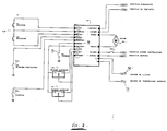
- Figure 2 corresponds to the general connection diagram of the electronic module.
- Figure 3 is a block diagram of this application.
- Referring now to Figure 1 of the drawings, the mechanism there shown includes the electronic module (1) and the reducer motor (2) the traction or drive cable (9) and the guide rail or track (8) with the drive plate (6) moved by the cable (9). We can also appreciate the three Areas: upper (12), protected (11) and lower (10), as well as the lower stop (7).
- The module (1) is connected to the reducer motor (2) and to the two sensors, upper (3) and lower (4), by means of wiring (9').
- As regards Figure 2, the assembly in this diagram of the module will be developed as the different functions of the assembly are explained.
- In this respect we will point out that the system has a series of integrated functions based on push buttons and switches.
- When the push button (13) is activated (pressed) for a time shorter than "X", the raise/lower function of the glass pane is maintained until a stop is detected, until the pressing of either of the two keys (17, 19) of this push button or until any sticking or trapping is detected during ascending travel.
- When one of the keys (17) or (19) of the push button panel is pressed for a time longer than "X", the raise/lower function is maintained while the key is kept pressed down, as long as no trapping or sticking is detected or a stop is reached. On reaching one of the two stops, upper or lower, the fact of keeping the key pressed down for travel towards the stop does not activate the motor (2).
- There is also the possibility of operating this system by means of a double-contact key in each of its two travels. (See Figure 3).
- By pressing the key strongly for raising or lowering and then releasing it, the glass pane travels up or down until it reaches the corresponding stop. The movement can be interrupted by means of pressing one of the keys for raising or lowering again.
- By pressing the key for raising or lowering without pressing fully, the glass pane travels up or down while the key is kept pressed.
- In order to eliminate the antinipping system, a contact (20) is included in which, by means of a button switch (14), it is possible to eliminate the said system.
- By means of a push button; the elimination of the means of protection through a push button is the function by which, by means of the continuous and simultaneous operation of the push button (14) and the key (17), the window can be closed.
- By means of a switch; with the switch (14) activated in the ON position, the antinipping protection system is eliminated each time that the glass pane is raised.
- Operation with the car door key; there is the availability of connecting the window winder/sunroof to the central locking system (29). With this function, all the windows of the vehicle that have this centralized system incorporated are moved towards their final position, window closed, when the central locking system is engaged.
- During the application of this function, the antinipping system is activated.
- Control without the key in the ignition. With the vehicle door open, the key removed from the ignition, with (25) without voltage, if any door of the vehicle is open, with the switch (15) in the ON position, control is still maintained over the window winder system/sunroof.
- Control without the key in the ignition. With the doors closed; the key removed from the ignition, with (25) without voltage, and the doors closed, with the switch (15) in the OFF position, the window winder system/sunroof can be controlled for a time of "T" seconds after the doors are closed.
- Summer position; the assembly has an input for the summer position (28), which is activated by operating the switch (16) and then the central locking system (29). This position means that the vehicle window panes open to a distance of 3 cms. from the upper part of the window, so that an air flow is established inside the vehicle and the passeniger compartment can be cooled.
- There is also the possibility of inserting a temperature sensor (32) inside the said compartment, so that when a certain temperature is reached, 30°C. for example, the sensor is activated and sends a signal to the control unit in such a way that the vehicle windows are then set to the summer position.
- Rain position; in the same way, there is also the possibility of fitting a moisture sensor (30), which is activated when a certain degree of humidity is reached and sends a signal to the control unit, which instantly moves the vehicle window panes to their final, window closed, position.
- With reference to Figure 2, other functions not expressly mentioned previously are as follows:
- (18) Common push button.
- (21) Permanent positive battery.
- (22) Ground.
- (23) Output to the upper sensor (3).
- (24) Output to the lower sensor (4).
- (26) Motor (2).
- (27) Motor (2).
- (28) Summer position.
- (30) Door contact.
- In the same way, with reference to Figure 3, the following positions are represented:
- (2) Motor.
- (35) Motor speed control.
- (36) Converter.
- (37) Input selection and filter.
- (38) Central processing unit.
- (39) Motor control and power driver.
- (3) Sensor.
- (34) Protection blocks.
- (15) Door push button.
- (14) Summer position push buttom.
- (18) Common push button.
- It is important to point out, once having described the nature and advantages of this invention, the non-restrictive character of the same, inasmuch as changes in the shape, material or sizes of its constituent parts will not in any way alter its essentiality, as long as they do not mean a substantial variation in the assembly.
Claims (4)
Applications Claiming Priority (2)
| Application Number | Priority Date | Filing Date | Title |
|---|---|---|---|
| ES9201697A ES2064213B1 (en) | 1992-08-12 | 1992-08-12 | ANTI-PINCH PROTECTION SYSTEM FOR LIFTS AND LIFTING CEILINGS AND ELECTRIC SLIDES OF AUTOMOBILE VEHICLES. |
| ES9201697 | 1992-08-12 |
Publications (2)
| Publication Number | Publication Date |
|---|---|
| EP0584033A1 true EP0584033A1 (en) | 1994-02-23 |
| EP0584033B1 EP0584033B1 (en) | 1998-02-18 |
Family
ID=8277968
Family Applications (1)
| Application Number | Title | Priority Date | Filing Date |
|---|---|---|---|
| EP19930500121 Expired - Lifetime EP0584033B1 (en) | 1992-08-12 | 1993-08-06 | Antinipping protection system for window winders and sunroofs in automobile vehicles |
Country Status (3)
| Country | Link |
|---|---|
| EP (1) | EP0584033B1 (en) |
| DE (1) | DE69317023T2 (en) |
| ES (2) | ES2064213B1 (en) |
Cited By (4)
| Publication number | Priority date | Publication date | Assignee | Title |
|---|---|---|---|---|
| FR2718183A1 (en) * | 1994-04-04 | 1995-10-06 | Mecanismos Aux Ind | Advanced window lifter for automobiles. |
| EP0758708A1 (en) * | 1995-08-11 | 1997-02-19 | Grupo Antolin-Ingenieria, S.A. | Anti-nipping device |
| EP0761922A1 (en) * | 1995-08-11 | 1997-03-12 | Grupo Antolin-Ingenieria, S.A. | Self-adjustable position detector in antinipping devices for automobile vehicles |
| CN103434508A (en) * | 2013-08-09 | 2013-12-11 | 浙江吉利汽车研究院有限公司 | Automatic control method and automatic control system for scuttle |
Citations (5)
| Publication number | Priority date | Publication date | Assignee | Title |
|---|---|---|---|---|
| EP0054581A1 (en) * | 1980-12-19 | 1982-06-30 | Dictator-Technik Ruef & Co. | Drive for controlling doors or portals |
| DE3206243A1 (en) * | 1982-02-20 | 1983-09-01 | Küster & Co GmbH, 6332 Ehringshausen | Safety circuit for an electromotively driven window lifter |
| DE3736400A1 (en) * | 1987-10-28 | 1989-05-11 | Reitter & Schefenacker Kg | Safety device for movable parts, preferably for window raisers and sun roofs of motor vehicles |
| DE3911493A1 (en) * | 1989-04-08 | 1990-10-11 | Bayerische Motoren Werke Ag | Safety device for motively moved closing parts |
| EP0473068A1 (en) * | 1990-08-24 | 1992-03-04 | Siemens Aktiengesellschaft | Apparatus for closing individual motor-driven windows of a motor-vehicle |
Family Cites Families (4)
| Publication number | Priority date | Publication date | Assignee | Title |
|---|---|---|---|---|
| US4198573A (en) * | 1978-01-09 | 1980-04-15 | Reneau Paul A | Automatic memory and environmental security system |
| ES2040796T3 (en) * | 1988-09-21 | 1993-11-01 | Siemens Aktiengesellschaft | DRIVE BY ELECTRIC MOTOR, ESPECIALLY REGULATION DRIVE FOR A MOTORIZED VEHICLE. |
| IT1241186B (en) * | 1990-03-13 | 1993-12-29 | Fabbrica Italiana Serrature Torino S.P.A. | COMMAND DEVICE FOR SLIDING ELEMENTS OF A VEHICLE, OPERABLE FROM THE OUTSIDE OF THE VEHICLE ITSELF. |
| DE69218955T2 (en) * | 1991-01-18 | 1997-10-09 | Riken Kk | Control circuit for a DC motor |
-
1992
- 1992-08-12 ES ES9201697A patent/ES2064213B1/en not_active Expired - Lifetime
-
1993
- 1993-08-06 DE DE1993617023 patent/DE69317023T2/en not_active Expired - Fee Related
- 1993-08-06 EP EP19930500121 patent/EP0584033B1/en not_active Expired - Lifetime
- 1993-08-06 ES ES93500121T patent/ES2115040T3/en not_active Expired - Lifetime
Patent Citations (5)
| Publication number | Priority date | Publication date | Assignee | Title |
|---|---|---|---|---|
| EP0054581A1 (en) * | 1980-12-19 | 1982-06-30 | Dictator-Technik Ruef & Co. | Drive for controlling doors or portals |
| DE3206243A1 (en) * | 1982-02-20 | 1983-09-01 | Küster & Co GmbH, 6332 Ehringshausen | Safety circuit for an electromotively driven window lifter |
| DE3736400A1 (en) * | 1987-10-28 | 1989-05-11 | Reitter & Schefenacker Kg | Safety device for movable parts, preferably for window raisers and sun roofs of motor vehicles |
| DE3911493A1 (en) * | 1989-04-08 | 1990-10-11 | Bayerische Motoren Werke Ag | Safety device for motively moved closing parts |
| EP0473068A1 (en) * | 1990-08-24 | 1992-03-04 | Siemens Aktiengesellschaft | Apparatus for closing individual motor-driven windows of a motor-vehicle |
Cited By (6)
| Publication number | Priority date | Publication date | Assignee | Title |
|---|---|---|---|---|
| FR2718183A1 (en) * | 1994-04-04 | 1995-10-06 | Mecanismos Aux Ind | Advanced window lifter for automobiles. |
| ES2125742A1 (en) * | 1994-04-04 | 1999-03-01 | Mecanismos Aux Ind | Window control |
| EP0758708A1 (en) * | 1995-08-11 | 1997-02-19 | Grupo Antolin-Ingenieria, S.A. | Anti-nipping device |
| EP0761922A1 (en) * | 1995-08-11 | 1997-03-12 | Grupo Antolin-Ingenieria, S.A. | Self-adjustable position detector in antinipping devices for automobile vehicles |
| CN103434508A (en) * | 2013-08-09 | 2013-12-11 | 浙江吉利汽车研究院有限公司 | Automatic control method and automatic control system for scuttle |
| CN103434508B (en) * | 2013-08-09 | 2016-04-27 | 浙江吉利汽车研究院有限公司 | A kind of skylight autocontrol method and system |
Also Published As
| Publication number | Publication date |
|---|---|
| ES2064213R (en) | 1996-08-01 |
| ES2115040T3 (en) | 1998-06-16 |
| ES2064213B1 (en) | 1997-02-16 |
| DE69317023D1 (en) | 1998-03-26 |
| EP0584033B1 (en) | 1998-02-18 |
| DE69317023T2 (en) | 1998-10-08 |
| ES2064213A2 (en) | 1995-01-16 |
Similar Documents
| Publication | Publication Date | Title |
|---|---|---|
| US5982126A (en) | Power closure panel control apparatus | |
| US7219945B1 (en) | Power lift gate for automotive vehicle | |
| US6667591B2 (en) | Method and device for increasing the allowed motor power of a motorized garage door operator | |
| US6046562A (en) | Security system for automatic door | |
| JP4567194B2 (en) | Method and apparatus for electrically controlling and regulating the movement of an electrically actuated assembly of a motor vehicle | |
| US20050179409A1 (en) | Opening and closing body control device | |
| KR20040110463A (en) | Safety Apparatus of Automobile Sun Roof | |
| CN102029879B (en) | The vehicle anti-pinch with variable thresholding controls and method | |
| CA1167551A (en) | Door operation control apparatus | |
| JPH11510998A (en) | Device for electronic monitoring of a regulating drive arranged in a vehicle | |
| US7183732B2 (en) | Motorized barrier operator system for controlling a stopped, partially open barrier and related methods | |
| CZ57299A3 (en) | Adjusting drive, particularly drive with driving electric motor | |
| EP0584033B1 (en) | Antinipping protection system for window winders and sunroofs in automobile vehicles | |
| US6308461B1 (en) | Method and system for detecting an object in the path of an automotive window utilizing a piezoelectric sensor | |
| US3815005A (en) | Protective device for electrically operated windows, especially of motor vehicles | |
| GB2199963A (en) | Control circuit for electrically operated windows | |
| EP1632633A1 (en) | Mover opening/closing control device | |
| KR20010029517A (en) | Actuator, in particular an electric motor gear drive system, for moving closure parts operated by extraneous force | |
| JPS625932Y2 (en) | ||
| JP2020533505A (en) | Automotive doors, especially sliding doors for automobiles | |
| JPS6070622A (en) | Switching drive device of vehicle motor drive facility | |
| KR100550608B1 (en) | apparatus to operate sunroof of automobile automatically | |
| JPH0737022Y2 (en) | Position sensor for automobile wind regulator | |
| JPH0540221Y2 (en) | ||
| KR0107673Y1 (en) | An emergency opening window device of a car |
Legal Events
| Date | Code | Title | Description |
|---|---|---|---|
| PUAI | Public reference made under article 153(3) epc to a published international application that has entered the european phase |
Free format text: ORIGINAL CODE: 0009012 |
|
| AK | Designated contracting states |
Kind code of ref document: A1 Designated state(s): DE ES FR GB IT |
|
| 17P | Request for examination filed |
Effective date: 19940818 |
|
| 17Q | First examination report despatched |
Effective date: 19960110 |
|
| GRAG | Despatch of communication of intention to grant |
Free format text: ORIGINAL CODE: EPIDOS AGRA |
|
| GRAH | Despatch of communication of intention to grant a patent |
Free format text: ORIGINAL CODE: EPIDOS IGRA |
|
| GRAH | Despatch of communication of intention to grant a patent |
Free format text: ORIGINAL CODE: EPIDOS IGRA |
|
| GRAA | (expected) grant |
Free format text: ORIGINAL CODE: 0009210 |
|
| AK | Designated contracting states |
Kind code of ref document: B1 Designated state(s): DE ES FR GB IT |
|
| REF | Corresponds to: |
Ref document number: 69317023 Country of ref document: DE Date of ref document: 19980326 |
|
| ITF | It: translation for a ep patent filed |
Owner name: MODIANO & ASSOCIATI S.R.L. |
|
| REG | Reference to a national code |
Ref country code: ES Ref legal event code: FG2A Ref document number: 2115040 Country of ref document: ES Kind code of ref document: T3 |
|
| ET | Fr: translation filed | ||
| PLBE | No opposition filed within time limit |
Free format text: ORIGINAL CODE: 0009261 |
|
| STAA | Information on the status of an ep patent application or granted ep patent |
Free format text: STATUS: NO OPPOSITION FILED WITHIN TIME LIMIT |
|
| 26N | No opposition filed | ||
| PGFP | Annual fee paid to national office [announced via postgrant information from national office to epo] |
Ref country code: FR Payment date: 19990721 Year of fee payment: 7 |
|
| PGFP | Annual fee paid to national office [announced via postgrant information from national office to epo] |
Ref country code: GB Payment date: 19990726 Year of fee payment: 7 |
|
| PGFP | Annual fee paid to national office [announced via postgrant information from national office to epo] |
Ref country code: ES Payment date: 19990825 Year of fee payment: 7 |
|
| PGFP | Annual fee paid to national office [announced via postgrant information from national office to epo] |
Ref country code: DE Payment date: 19991021 Year of fee payment: 7 |
|
| PG25 | Lapsed in a contracting state [announced via postgrant information from national office to epo] |
Ref country code: GB Free format text: LAPSE BECAUSE OF NON-PAYMENT OF DUE FEES Effective date: 20000806 |
|
| PG25 | Lapsed in a contracting state [announced via postgrant information from national office to epo] |
Ref country code: ES Free format text: LAPSE BECAUSE OF NON-PAYMENT OF DUE FEES Effective date: 20000807 |
|
| GBPC | Gb: european patent ceased through non-payment of renewal fee |
Effective date: 20000806 |
|
| PG25 | Lapsed in a contracting state [announced via postgrant information from national office to epo] |
Ref country code: FR Free format text: LAPSE BECAUSE OF NON-PAYMENT OF DUE FEES Effective date: 20010430 |
|
| PG25 | Lapsed in a contracting state [announced via postgrant information from national office to epo] |
Ref country code: DE Free format text: LAPSE BECAUSE OF NON-PAYMENT OF DUE FEES Effective date: 20010501 |
|
| REG | Reference to a national code |
Ref country code: FR Ref legal event code: ST |
|
| REG | Reference to a national code |
Ref country code: ES Ref legal event code: FD2A Effective date: 20010911 |
|
| PG25 | Lapsed in a contracting state [announced via postgrant information from national office to epo] |
Ref country code: IT Free format text: LAPSE BECAUSE OF NON-PAYMENT OF DUE FEES Effective date: 20050806 |