EP0583301B1 - Elektrisch antreibbares kraftfahrzeug - Google Patents
Elektrisch antreibbares kraftfahrzeug Download PDFInfo
- Publication number
- EP0583301B1 EP0583301B1 EP92909462A EP92909462A EP0583301B1 EP 0583301 B1 EP0583301 B1 EP 0583301B1 EP 92909462 A EP92909462 A EP 92909462A EP 92909462 A EP92909462 A EP 92909462A EP 0583301 B1 EP0583301 B1 EP 0583301B1
- Authority
- EP
- European Patent Office
- Prior art keywords
- motor vehicle
- housing
- electrically powered
- vehicle according
- face
- Prior art date
- Legal status (The legal status is an assumption and is not a legal conclusion. Google has not performed a legal analysis and makes no representation as to the accuracy of the status listed.)
- Expired - Lifetime
Links
Images


Classifications
-
- H—ELECTRICITY
- H02—GENERATION; CONVERSION OR DISTRIBUTION OF ELECTRIC POWER
- H02K—DYNAMO-ELECTRIC MACHINES
- H02K5/00—Casings; Enclosures; Supports
- H02K5/04—Casings or enclosures characterised by the shape, form or construction thereof
- H02K5/20—Casings or enclosures characterised by the shape, form or construction thereof with channels or ducts for flow of cooling medium
- H02K5/203—Casings or enclosures characterised by the shape, form or construction thereof with channels or ducts for flow of cooling medium specially adapted for liquids, e.g. cooling jackets
-
- B—PERFORMING OPERATIONS; TRANSPORTING
- B60—VEHICLES IN GENERAL
- B60K—ARRANGEMENT OR MOUNTING OF PROPULSION UNITS OR OF TRANSMISSIONS IN VEHICLES; ARRANGEMENT OR MOUNTING OF PLURAL DIVERSE PRIME-MOVERS IN VEHICLES; AUXILIARY DRIVES FOR VEHICLES; INSTRUMENTATION OR DASHBOARDS FOR VEHICLES; ARRANGEMENTS IN CONNECTION WITH COOLING, AIR INTAKE, GAS EXHAUST OR FUEL SUPPLY OF PROPULSION UNITS IN VEHICLES
- B60K6/00—Arrangement or mounting of plural diverse prime-movers for mutual or common propulsion, e.g. hybrid propulsion systems comprising electric motors and internal combustion engines
- B60K6/20—Arrangement or mounting of plural diverse prime-movers for mutual or common propulsion, e.g. hybrid propulsion systems comprising electric motors and internal combustion engines the prime-movers consisting of electric motors and internal combustion engines, e.g. HEVs
- B60K6/22—Arrangement or mounting of plural diverse prime-movers for mutual or common propulsion, e.g. hybrid propulsion systems comprising electric motors and internal combustion engines the prime-movers consisting of electric motors and internal combustion engines, e.g. HEVs characterised by apparatus, components or means specially adapted for HEVs
- B60K6/26—Arrangement or mounting of plural diverse prime-movers for mutual or common propulsion, e.g. hybrid propulsion systems comprising electric motors and internal combustion engines the prime-movers consisting of electric motors and internal combustion engines, e.g. HEVs characterised by apparatus, components or means specially adapted for HEVs characterised by the motors or the generators
-
- B—PERFORMING OPERATIONS; TRANSPORTING
- B60—VEHICLES IN GENERAL
- B60K—ARRANGEMENT OR MOUNTING OF PROPULSION UNITS OR OF TRANSMISSIONS IN VEHICLES; ARRANGEMENT OR MOUNTING OF PLURAL DIVERSE PRIME-MOVERS IN VEHICLES; AUXILIARY DRIVES FOR VEHICLES; INSTRUMENTATION OR DASHBOARDS FOR VEHICLES; ARRANGEMENTS IN CONNECTION WITH COOLING, AIR INTAKE, GAS EXHAUST OR FUEL SUPPLY OF PROPULSION UNITS IN VEHICLES
- B60K6/00—Arrangement or mounting of plural diverse prime-movers for mutual or common propulsion, e.g. hybrid propulsion systems comprising electric motors and internal combustion engines
- B60K6/20—Arrangement or mounting of plural diverse prime-movers for mutual or common propulsion, e.g. hybrid propulsion systems comprising electric motors and internal combustion engines the prime-movers consisting of electric motors and internal combustion engines, e.g. HEVs
- B60K6/42—Arrangement or mounting of plural diverse prime-movers for mutual or common propulsion, e.g. hybrid propulsion systems comprising electric motors and internal combustion engines the prime-movers consisting of electric motors and internal combustion engines, e.g. HEVs characterised by the architecture of the hybrid electric vehicle
- B60K6/48—Parallel type
-
- B—PERFORMING OPERATIONS; TRANSPORTING
- B60—VEHICLES IN GENERAL
- B60K—ARRANGEMENT OR MOUNTING OF PROPULSION UNITS OR OF TRANSMISSIONS IN VEHICLES; ARRANGEMENT OR MOUNTING OF PLURAL DIVERSE PRIME-MOVERS IN VEHICLES; AUXILIARY DRIVES FOR VEHICLES; INSTRUMENTATION OR DASHBOARDS FOR VEHICLES; ARRANGEMENTS IN CONNECTION WITH COOLING, AIR INTAKE, GAS EXHAUST OR FUEL SUPPLY OF PROPULSION UNITS IN VEHICLES
- B60K6/00—Arrangement or mounting of plural diverse prime-movers for mutual or common propulsion, e.g. hybrid propulsion systems comprising electric motors and internal combustion engines
- B60K6/20—Arrangement or mounting of plural diverse prime-movers for mutual or common propulsion, e.g. hybrid propulsion systems comprising electric motors and internal combustion engines the prime-movers consisting of electric motors and internal combustion engines, e.g. HEVs
- B60K6/50—Architecture of the driveline characterised by arrangement or kind of transmission units
- B60K6/52—Driving a plurality of drive axles, e.g. four-wheel drive
-
- B—PERFORMING OPERATIONS; TRANSPORTING
- B60—VEHICLES IN GENERAL
- B60L—PROPULSION OF ELECTRICALLY-PROPELLED VEHICLES; SUPPLYING ELECTRIC POWER FOR AUXILIARY EQUIPMENT OF ELECTRICALLY-PROPELLED VEHICLES; ELECTRODYNAMIC BRAKE SYSTEMS FOR VEHICLES IN GENERAL; MAGNETIC SUSPENSION OR LEVITATION FOR VEHICLES; MONITORING OPERATING VARIABLES OF ELECTRICALLY-PROPELLED VEHICLES; ELECTRIC SAFETY DEVICES FOR ELECTRICALLY-PROPELLED VEHICLES
- B60L1/00—Supplying electric power to auxiliary equipment of vehicles
- B60L1/02—Supplying electric power to auxiliary equipment of vehicles to electric heating circuits
-
- B—PERFORMING OPERATIONS; TRANSPORTING
- B60—VEHICLES IN GENERAL
- B60L—PROPULSION OF ELECTRICALLY-PROPELLED VEHICLES; SUPPLYING ELECTRIC POWER FOR AUXILIARY EQUIPMENT OF ELECTRICALLY-PROPELLED VEHICLES; ELECTRODYNAMIC BRAKE SYSTEMS FOR VEHICLES IN GENERAL; MAGNETIC SUSPENSION OR LEVITATION FOR VEHICLES; MONITORING OPERATING VARIABLES OF ELECTRICALLY-PROPELLED VEHICLES; ELECTRIC SAFETY DEVICES FOR ELECTRICALLY-PROPELLED VEHICLES
- B60L3/00—Electric devices on electrically-propelled vehicles for safety purposes; Monitoring operating variables, e.g. speed, deceleration or energy consumption
- B60L3/0023—Detecting, eliminating, remedying or compensating for drive train abnormalities, e.g. failures within the drive train
- B60L3/0061—Detecting, eliminating, remedying or compensating for drive train abnormalities, e.g. failures within the drive train relating to electrical machines
-
- B—PERFORMING OPERATIONS; TRANSPORTING
- B60—VEHICLES IN GENERAL
- B60L—PROPULSION OF ELECTRICALLY-PROPELLED VEHICLES; SUPPLYING ELECTRIC POWER FOR AUXILIARY EQUIPMENT OF ELECTRICALLY-PROPELLED VEHICLES; ELECTRODYNAMIC BRAKE SYSTEMS FOR VEHICLES IN GENERAL; MAGNETIC SUSPENSION OR LEVITATION FOR VEHICLES; MONITORING OPERATING VARIABLES OF ELECTRICALLY-PROPELLED VEHICLES; ELECTRIC SAFETY DEVICES FOR ELECTRICALLY-PROPELLED VEHICLES
- B60L50/00—Electric propulsion with power supplied within the vehicle
- B60L50/10—Electric propulsion with power supplied within the vehicle using propulsion power supplied by engine-driven generators, e.g. generators driven by combustion engines
- B60L50/16—Electric propulsion with power supplied within the vehicle using propulsion power supplied by engine-driven generators, e.g. generators driven by combustion engines with provision for separate direct mechanical propulsion
-
- B—PERFORMING OPERATIONS; TRANSPORTING
- B60—VEHICLES IN GENERAL
- B60L—PROPULSION OF ELECTRICALLY-PROPELLED VEHICLES; SUPPLYING ELECTRIC POWER FOR AUXILIARY EQUIPMENT OF ELECTRICALLY-PROPELLED VEHICLES; ELECTRODYNAMIC BRAKE SYSTEMS FOR VEHICLES IN GENERAL; MAGNETIC SUSPENSION OR LEVITATION FOR VEHICLES; MONITORING OPERATING VARIABLES OF ELECTRICALLY-PROPELLED VEHICLES; ELECTRIC SAFETY DEVICES FOR ELECTRICALLY-PROPELLED VEHICLES
- B60L50/00—Electric propulsion with power supplied within the vehicle
- B60L50/50—Electric propulsion with power supplied within the vehicle using propulsion power supplied by batteries or fuel cells
- B60L50/60—Electric propulsion with power supplied within the vehicle using propulsion power supplied by batteries or fuel cells using power supplied by batteries
- B60L50/66—Arrangements of batteries
-
- H—ELECTRICITY
- H02—GENERATION; CONVERSION OR DISTRIBUTION OF ELECTRIC POWER
- H02K—DYNAMO-ELECTRIC MACHINES
- H02K5/00—Casings; Enclosures; Supports
- H02K5/04—Casings or enclosures characterised by the shape, form or construction thereof
- H02K5/20—Casings or enclosures characterised by the shape, form or construction thereof with channels or ducts for flow of cooling medium
-
- B—PERFORMING OPERATIONS; TRANSPORTING
- B60—VEHICLES IN GENERAL
- B60K—ARRANGEMENT OR MOUNTING OF PROPULSION UNITS OR OF TRANSMISSIONS IN VEHICLES; ARRANGEMENT OR MOUNTING OF PLURAL DIVERSE PRIME-MOVERS IN VEHICLES; AUXILIARY DRIVES FOR VEHICLES; INSTRUMENTATION OR DASHBOARDS FOR VEHICLES; ARRANGEMENTS IN CONNECTION WITH COOLING, AIR INTAKE, GAS EXHAUST OR FUEL SUPPLY OF PROPULSION UNITS IN VEHICLES
- B60K1/00—Arrangement or mounting of electrical propulsion units
- B60K2001/003—Arrangement or mounting of electrical propulsion units with means for cooling the electrical propulsion units
-
- B—PERFORMING OPERATIONS; TRANSPORTING
- B60—VEHICLES IN GENERAL
- B60L—PROPULSION OF ELECTRICALLY-PROPELLED VEHICLES; SUPPLYING ELECTRIC POWER FOR AUXILIARY EQUIPMENT OF ELECTRICALLY-PROPELLED VEHICLES; ELECTRODYNAMIC BRAKE SYSTEMS FOR VEHICLES IN GENERAL; MAGNETIC SUSPENSION OR LEVITATION FOR VEHICLES; MONITORING OPERATING VARIABLES OF ELECTRICALLY-PROPELLED VEHICLES; ELECTRIC SAFETY DEVICES FOR ELECTRICALLY-PROPELLED VEHICLES
- B60L2220/00—Electrical machine types; Structures or applications thereof
- B60L2220/10—Electrical machine types
- B60L2220/14—Synchronous machines
-
- B—PERFORMING OPERATIONS; TRANSPORTING
- B60—VEHICLES IN GENERAL
- B60L—PROPULSION OF ELECTRICALLY-PROPELLED VEHICLES; SUPPLYING ELECTRIC POWER FOR AUXILIARY EQUIPMENT OF ELECTRICALLY-PROPELLED VEHICLES; ELECTRODYNAMIC BRAKE SYSTEMS FOR VEHICLES IN GENERAL; MAGNETIC SUSPENSION OR LEVITATION FOR VEHICLES; MONITORING OPERATING VARIABLES OF ELECTRICALLY-PROPELLED VEHICLES; ELECTRIC SAFETY DEVICES FOR ELECTRICALLY-PROPELLED VEHICLES
- B60L2240/00—Control parameters of input or output; Target parameters
- B60L2240/10—Vehicle control parameters
- B60L2240/36—Temperature of vehicle components or parts
-
- H—ELECTRICITY
- H02—GENERATION; CONVERSION OR DISTRIBUTION OF ELECTRIC POWER
- H02K—DYNAMO-ELECTRIC MACHINES
- H02K5/00—Casings; Enclosures; Supports
- H02K5/04—Casings or enclosures characterised by the shape, form or construction thereof
- H02K5/20—Casings or enclosures characterised by the shape, form or construction thereof with channels or ducts for flow of cooling medium
- H02K5/207—Casings or enclosures characterised by the shape, form or construction thereof with channels or ducts for flow of cooling medium with openings in the casing specially adapted for ambient air
-
- Y—GENERAL TAGGING OF NEW TECHNOLOGICAL DEVELOPMENTS; GENERAL TAGGING OF CROSS-SECTIONAL TECHNOLOGIES SPANNING OVER SEVERAL SECTIONS OF THE IPC; TECHNICAL SUBJECTS COVERED BY FORMER USPC CROSS-REFERENCE ART COLLECTIONS [XRACs] AND DIGESTS
- Y02—TECHNOLOGIES OR APPLICATIONS FOR MITIGATION OR ADAPTATION AGAINST CLIMATE CHANGE
- Y02T—CLIMATE CHANGE MITIGATION TECHNOLOGIES RELATED TO TRANSPORTATION
- Y02T10/00—Road transport of goods or passengers
- Y02T10/60—Other road transportation technologies with climate change mitigation effect
- Y02T10/62—Hybrid vehicles
-
- Y—GENERAL TAGGING OF NEW TECHNOLOGICAL DEVELOPMENTS; GENERAL TAGGING OF CROSS-SECTIONAL TECHNOLOGIES SPANNING OVER SEVERAL SECTIONS OF THE IPC; TECHNICAL SUBJECTS COVERED BY FORMER USPC CROSS-REFERENCE ART COLLECTIONS [XRACs] AND DIGESTS
- Y02—TECHNOLOGIES OR APPLICATIONS FOR MITIGATION OR ADAPTATION AGAINST CLIMATE CHANGE
- Y02T—CLIMATE CHANGE MITIGATION TECHNOLOGIES RELATED TO TRANSPORTATION
- Y02T10/00—Road transport of goods or passengers
- Y02T10/60—Other road transportation technologies with climate change mitigation effect
- Y02T10/64—Electric machine technologies in electromobility
-
- Y—GENERAL TAGGING OF NEW TECHNOLOGICAL DEVELOPMENTS; GENERAL TAGGING OF CROSS-SECTIONAL TECHNOLOGIES SPANNING OVER SEVERAL SECTIONS OF THE IPC; TECHNICAL SUBJECTS COVERED BY FORMER USPC CROSS-REFERENCE ART COLLECTIONS [XRACs] AND DIGESTS
- Y02—TECHNOLOGIES OR APPLICATIONS FOR MITIGATION OR ADAPTATION AGAINST CLIMATE CHANGE
- Y02T—CLIMATE CHANGE MITIGATION TECHNOLOGIES RELATED TO TRANSPORTATION
- Y02T10/00—Road transport of goods or passengers
- Y02T10/60—Other road transportation technologies with climate change mitigation effect
- Y02T10/70—Energy storage systems for electromobility, e.g. batteries
-
- Y—GENERAL TAGGING OF NEW TECHNOLOGICAL DEVELOPMENTS; GENERAL TAGGING OF CROSS-SECTIONAL TECHNOLOGIES SPANNING OVER SEVERAL SECTIONS OF THE IPC; TECHNICAL SUBJECTS COVERED BY FORMER USPC CROSS-REFERENCE ART COLLECTIONS [XRACs] AND DIGESTS
- Y02—TECHNOLOGIES OR APPLICATIONS FOR MITIGATION OR ADAPTATION AGAINST CLIMATE CHANGE
- Y02T—CLIMATE CHANGE MITIGATION TECHNOLOGIES RELATED TO TRANSPORTATION
- Y02T10/00—Road transport of goods or passengers
- Y02T10/60—Other road transportation technologies with climate change mitigation effect
- Y02T10/7072—Electromobility specific charging systems or methods for batteries, ultracapacitors, supercapacitors or double-layer capacitors
Definitions
- the invention relates to an electrically drivable motor vehicle.
- Electric vehicles or vehicles with a so-called hybrid drive i.e. both an internal combustion engine and an electric motor, are part of the prior art.
- the literature “Gahleitner: Status of the Development of Electric Road Vehicles 1989, ⁇ ZE, Volume 42, Issue 5, May 1989, page 979 ff.” Provides an overview of the current state of the art.
- a permanent magnet synchronous motor has proven to be advantageous, which can be easily integrated into a hybrid vehicle with a small and compact unit, the cardan shaft of which is driven by an internal combustion engine .
- the object of the invention is to provide a generic engine that is easy to manufacture despite the corresponding devices for supplying coolant.
- a permanent magnet synchronous motor is used as the electric motor, which is characterized in particular by the fact that it can be very heavily loaded for a short time, it can be driven with considerable current intensities for a limited period of time and is therefore particularly suitable for road vehicles: to meet the load when starting off.
- the limits of the current consumption are given less by the motor itself than by the control electronics and by accumulator or battery capacities.
- the strong short-term load of the permanent magnet synchronous motor is of great advantage, especially in vehicles where stationary operation rarely occurs, such as road vehicles, which have to be braked or accelerated depending on the traffic situation.
- the housing for the motor is pot-shaped is.
- a corresponding cover closes off the housing, and this cover is provided in the area of the support surface on the front side of the side walls with openings through which the connections for the water channels are passed.
- the top-side supply of the cooling water channels allows the engine to be installed just before the rear axle differential, which ensures that the cable connections between the batteries in the rear luggage compartment and the engine can be kept extremely short.
- the use of the permanent magnet synchronous motor enables optimal use of the available space, especially since the cardan shaft - which is already present - is functionally integrated into the motor.
- Small-sized motors such as the permanent magnet synchronous motor have a low mechanical moment of inertia, which benefits the driving performance, particularly when shifting.
- air cooling is also provided by the flow through the housing, the circulation of the rotor ensuring a certain circulation.
- the air is not exchanged with the ambient air, but a closed air flow takes place, the air circulated inside the housing is passed through a heat exchanger and cooled there again. In this way it is avoided that air enriched with metal dust and the like is sucked in for cooling, this z. Metal dust containing T. ferromagnetic elements would deposit on the permanent magnet and shut down the motor after a short time.
- Reference number 10 shows a hybrid vehicle which has an internal combustion engine 16 and a transmission 12 connected to it in the area of the front wheels 18. At the transmission output there is an intermediate differential, from which a drive shaft acts on the front wheels 18, and the rear wheels 22 are driven via a propeller shaft 20 and a rear axle differential 14.
- an electric motor 24 is provided, which is supplied with electricity via a battery pack 26 and can drive the cardan shaft.
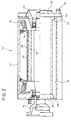
- the structure of the electric motor is shown in detail in FIG. 2.
- the electric motor has a rotor or rotor 32 and a stator or stator 34, the stator 34 is formed from individual windings with corresponding winding heads 36.
- the rotor 32 forms part of the propeller shaft 20 and is directly connected to it by a flange 44.
- the outside of the rotor 32 is pasted with permanent magnets 38, which are additionally bandaged.
- An air gap 40 is provided between the permanent magnets 38 and the stator 34.
- a housing 42 encloses the structure.
- the direct connection of the electric motor 24 to the rear axle differential 14 is provided, so that the electric motor has a first output via the cardan shaft to the front wheels and a second output via the rear axle differential to the rear wheels . Permanent four-wheel drive is thus achieved.
- the motor By designing the motor as a permanent magnet synchronous motor, a speed of rotation of the rotor 32 of up to 10,000 revolutions per minute is possible, so that a constant running of the motor 24 is possible even in high-speed vehicles without the motor being damaged.
- the housing 24 is approximately square in the outer shape of its radial cross section, so that the housing jacket has a relatively large amount of material in the corners of the square.
- a bore 50 is provided from the end face, which points in the direction of the differential, which begins at the end face of the pot-like housing 24 and extends through the wall almost to the bottom, which points in the direction of the internal combustion engine.
- two bores 52 and 54 are provided, which extend almost to the end face.
- the bores 50, 52 and 54 overlap so that an overall channel is formed in the inner region through which fluid can flow and which has a relatively large surface area due to the juxtaposition of the bores 50, 52 and 54.
- this wide channel which is composed of 50, 52 and 54, takes place solely through the circular bore 50, so that a connection of hoses or the like and the sealing is relatively simple.
- a connector 56 with a circular cross section is provided.
- the holes 52 and 54 made from behind form only two circular holes in the bottom, one of which is indicated at 58, and could accordingly be closed with simple circular plugs.
- a further bore 60 is provided through the bottom, via this bore 60, of which several can be attached in the same way, are in the quadrilaterals of the housing which is square in external cross section lying bores connected to each other, so that a circulation of cooling fluid can occur.
- the cover 62 to be placed on the end face after installation of the motor on the housing 24 has openings 56 in the area of the connection piece, so that these connection pieces pass through the cover 62 and no longer have to be interrupted and no sealing points between the cover and the housing are necessary.
- the end windings 36 are also arranged near the housing wall 42 and cast thermally conductively with this housing wall, so that the end windings, as particularly vulnerable points, are thermally cooled and are protected against overheating.
- air cooling can also be provided, with a closed cooling air circuit preferably being formed, which is therefore sucked out of air blown into the interior through the housing wall at a suitable point and passed in a closed circuit through a heat exchanger.
- a closed cooling air circuit preferably being formed, which is therefore sucked out of air blown into the interior through the housing wall at a suitable point and passed in a closed circuit through a heat exchanger.
Landscapes
- Engineering & Computer Science (AREA)
- Power Engineering (AREA)
- Transportation (AREA)
- Mechanical Engineering (AREA)
- Chemical & Material Sciences (AREA)
- Combustion & Propulsion (AREA)
- Sustainable Energy (AREA)
- Sustainable Development (AREA)
- Life Sciences & Earth Sciences (AREA)
- Motor Or Generator Cooling System (AREA)
- Electric Propulsion And Braking For Vehicles (AREA)
- Permanent Field Magnets Of Synchronous Machinery (AREA)
- Permanent Magnet Type Synchronous Machine (AREA)
- Hybrid Electric Vehicles (AREA)
- Arrangement Or Mounting Of Propulsion Units For Vehicles (AREA)
- Air-Conditioning For Vehicles (AREA)
- Reciprocating, Oscillating Or Vibrating Motors (AREA)
Description
- Die Erfindung bezieht sich auf ein elektrisch antreibbares Kraftfahrzeug.
- Elektrofahrzeuge oder Fahrzeuge mit einem sogenannten Hybridantrieb, also sowohl einem Verbrennungsmotor als auch einem Elektromotor, gehören zum Stand der Technik. Einen Überblick über den gegenwärtigen Stand der Technik bietet die Literaturstelle "Gahleitner: Stand der Entwicklung von Elektro-Straßenfahrzeugen 1989, ÖZE, Jahrgang 42, Heft 5, Mai 1989, Seite 979 ff.".
- Vor allem in Verbindung mit einer Kardanwelle, die direkt einen Teil des Läufers eines Motors bilden soll, hat sich ein Permanentmagnet-Synchronmotor als vorteilhaft erwiesen, der bei kleiner und kompakter Baueinheit gut in ein Hybridfahrzeug integriert werden kann, dessen Kardanwelle über eine Verbrennungskraftmaschine angetrieben ist.
- Aus der Literaturstelle "Eureka, Incorp: Engineering Materials & Design, 11 (1991) February, No. 2, Horton Kirby, Kent, GB" ist ein Elektromotor für Kraftfahrzeuge, insbesondere Hybridfahrzeuge bekannt, der ölgekühlt oder alternativ auch wassergekühlt betrieben wird. Damit wird erreicht, daß keine Temperaturen mehr auftreten, die oberhalb des Curie-Punktes der Permanentmagnete liegen. In dieser Literaturstelle wird die Verwendung von Neodym-Eisen-Bor-Magneten vorgeschlagen, die einen verhältnismäßig niedrigen Curie-Punkt besitzen.
- Der dabei vorgesehene Verlauf der Kühlflüssigkeit, unter anderem auch Wasser, ist jedoch verhältnismäßig kompliziert, insbesondere ist die Fertigungstechnik für derartige Motoren problematisch.
- Aufgabe der Erfindung ist es, einen gattungsgemäßen Motor zu schaffen, der trotz der entsprechenden Einrichtungen zur Zuführung von Kühlflüssigkeit leicht zu fertigen ist.
- Die Aufgabe wird gelöst durch den Hauptanspruch.
- Erfindungsgemäß ist vorgesehen, daß als Elektromotor ein Permanentmagnet-Synchronmotor verwendet wird, der sich vor allem dadurch auszeichnet, daß er kurzfristig sehr stark belastet werden kann, er kann für einen begrenzten Zeitraum mit erheblichen Stromstärken gefahren werden und eignet sich so insbesondere bei Straßenfahrzeugen dazu, die Belastung beim Anfahren zu erfüllen. Die Grenzen der Stromaufnahme sind weniger durch den Motor selbst als vielmehr durch die Steuerungselektronik und durch Akkumulator- oder Batteriekapazitäten gegeben. Gerade bei Fahrzeugen, bei denen selten ein stationärer Betrieb vorkommt, wie bei Straßenfahrzeugen, die je nach Verkehrslage abgebremst oder beschleunigt werden müssen, ist die starke Kurzzeitbelastung des Permanentmagnet-Synchronmotors von großem Vorteil.
- Mit Hilfe einer Flüssigkeitskühlung, insbesondere Wasserkühlung, kann die stehende Wärme abgeführt werden.
- Um hierbei zu einem günstigen Aufbau zu gelangen, ist vorgesehen, daß das Gehäuse für den Motor topfartig ausgebildet ist. Ein entsprechender Deckel schließt das Gehäuse ab, und dieser Deckel ist im Bereich der Auflagefläche an der Stirnseite der Seitenwände mit Öffnungen versehen, durch die die Anschlüsse für die Wasserkanäle hindurchgeführt sind.
- Damit sind keine Dichtungsstellen zwischen Deckel und Gehäuse mehr notwendig.
- Durch die kopfseitige Zufuhr der Kühlwasserkanäle ist eine Einbaulage des Motors kurz vor dem Hinterachsdifferential möglich, dadurch wird sichergestellt, daß die Kabelverbindungen zwischen den im rückwärtigen Gepäckraum untergebrachten Batterien und dem Motor extrem kurz gehalten werden können.
- Die Verwendung des Permanentmagnet-Synchronmotors ermöglicht die optimale Nutzung des zur Verfügung stehenden Bauraumes, zumal die Kardanwelle - die ohnehin vorhanden ist - in den Motor funktional integriert wird.
- Kleinbauende Motoren wie der Permanentmagnet-Synchronmotor haben ein geringes mechanisches Trägheitsmoment, was den Fahrleistungen insbesondere bei Schaltvorgängen zugute kommt.
- Weiterbildungen der Erfindung sind in den Unteransprüchen beschrieben.
- Gemäß einem besonderen Merkmal ist zusätzlich zur Wasserkühlung noch eine Luftkühlung durch die Durchströmung des Gehäuses vorgesehen, wobei das Umlaufen des Läufers für eine gewisse Zirkulation sorgt. Erfindungsgemäß jedoch wird die Luft nicht mit der Umgebungsluft ausgetauscht, sondern es findet ein geschlossener Luftstrom statt, die in dem Gehäuseinnern umgewälzte Luft wird durch einen Wärmetauscher geführt und dort wieder abgekühlt. Auf diese Weise wird vermieden, daß mit Metallstaub und ähnlichem angereicherte Luft zur Kühlung angesaugt wird, dieser z. T. ferromagnetische Elemente enthaltende Metallstaub würde sich auf den Permanentmagneten niederschlagen und nach kurzer Zeit den Motor stilllegen.
- Im folgenden wird die Erfindung anhand der Figur im Detail beschrieben. Es zeigen:
- Fig. 1
- eine Seitenansicht des erfindungsgemäßen Kraftfahrzeuges zur Darstellung der Einbaulage;
- Fig. 2
- eine teilweise geschnittene Seitenansicht des Elektromotors; und
- Fig. 3
- eine geschnittene Aufsicht auf den Elektromotor.
- Mit dem Bezugszeichen 10 ist ein Hybridfahrzeug dargestellt, das im Bereich der Vorderräder 18 eine Brennkraftmaschine 16 sowie ein daran anschließendes Getriebe 12 aufweist. Am Getriebeausgang befindet sich ein Zwischendifferential, von dem zum einen eine Antriebswelle auf die Vorderräder 18 wirkt, sowie über eine Kardanwelle 20 und ein Hinterachsdifferential 14 die Hinterräder 22 angetrieben werden.
- Zusätzlich ist ein Elektromotor 24 vorgesehen, der über einen Batteriesatz 26 mit Elektrizität versorgt wird und die Kardanwelle antreiben kann.
- Der Aufbau des Elektromotors ist in Fig. 2 im Detail dargestellt. Der Elektromotor besitzt einen Rotor oder Läufer 32 und einen Ständer oder Stator 34, der Stator 34 ist aus einzelnen Wicklungen mit entsprechenden Wikkelköpfen 36 gebildet.
- Der Rotor 32 bildet dabei einen Teil der Kardanwelle 20 und ist durch einen Flansch 44 direkt mit ihr verbunden. Die Außenseite des Rotors 32 ist mit Permanentmagneten 38 beklebt, die zusätzlich bandagiert sind. Zwischen den Permanentmagneten 38 und dem Stator 34 ist ein Luftspalt 40 vorgesehen. Ein Gehäuse 42 umschließt den Aufbau.
- Im Bereich 46, dem Ende 44 mit der angeflanschten Kardanwelle 20 gegenüberliegend ist die direkte Verbindung des Elektromotors 24 mit dem Hinterachsdifferential 14 vorgesehen, so daß der Elektromotor einen ersten Abtrieb über die Kardanwelle zu den Vorderrädern und einen zweiten Abtrieb über das Hinterachsdifferential zu den Hinterrädern hat. Damit wird ein permanenter Allradantrieb verwirklicht.
- Durch die Auslegung des Motors als Permanentmagnet-Synchronmotor ist eine Umdrehungszahl des Läufers 32 von bis zu 10 000 Umdrehungen pro Minute möglich, so daß auch bei schnellaufenden Fahrzeugen ein ständiges Mitlaufen des Motors 24 möglich ist, ohne daß der Motor beschädigt wird.
- Das Gehäuse 24 ist in der Außenform seines radialen Querschnittes etwa quadratisch, so daß der Gehäusemantel in den Ecken des Quadrates verhältnismäßig viel Material stehen hat. In diesem Bereich ist von der Stirnseite her, die in Richtung zum dem Differential weist, eine Bohrung 50 vorgesehen, die an der Stirnseite des topfartigen Gehäuses 24 beginnt und durch die Wandung bis fast zum Boden reicht, der in Richtung der Brennkraftmaschine weist.
- Etwas axial versetzt dazu sind vom Boden her zwei Bohrungen 52 und 54 vorgesehen, die fast bis zur Stirnseite reichen. Die Bohrungen 50, 52 und 54 überlappen sich, so daß in dem Innenbereich ein Gesamtkanal gebildet wird, durch den Fluid strömen kann und der aufgrund des Nebeneinanderliegens der Bohrungen 50, 52 und 54 eine verhältnismäßig große Oberfläche besitzt. Die Hinzuführung jedoch zu diesem breiten Kanal der sich aus 50, 52 und 54 zusammensetzt, findet allein durch die kreisförmige Bohrung 50 statt, so daß ein Anschluß von Schläuchen oder ähnlichem sowie die Abdichtung verhältnismäßig einfach ist. Zur weiteren Erleichterung dazu ist ein im Querschnitt kreisförmiger Stutzen 56 vorgesehen.
- Die von hinten vorgenommenen Bohrungen 52 und 54 bilden im Boden lediglich zwei kreisrunde Löcher, eines davon ist mit 58 angedeutet, und könnten dementsprechend mit einfachen kreisförmigen Stopfen verschlossen werden.
- Durch den Boden ist eine weitere Bohrung 60 vorgesehen, über diese Bohrung 60, von denen mehrere in gleicher Weise angebracht werden können, werden die in den Vierecken des im Außenquerschnitt quadratischen Gehäuses liegenden Bohrungen miteinander verbunden, so daß es zu einem Umlauf von Kühlungsfluid kommen kann.
- Der nach Einbau des Motors auf das Gehäuse 24 auf die Stirnseite aufzusetzende Deckel 62 besitzt im Bereich der Stutzen 56 Öffnungen, so daß diese Stutzen durch den Deckel 62 hindurchführen und nicht mehr unterbrochen werden müssen und keine Dichtungsstellen zwischen Deckel und Gehäuse notwendig sind.
- In einer bevorzugten Ausführung sind auch die Wickelköpfe 36 nahe der Gehäusewand 42 angeordnet und thermisch leitfähig mit dieser Gehäusewand vergossen, so daß auch die Wickelköpfe als besonders gefährdete Stellen thermisch gekühlt sind und gegen Überhitzung geschützt sind.
- Zusätzlich zu der Wasserkühlung kann noch eine Luftkühlung vorgesehen werden, wobei in bevorzugter Weise ein geschlossener Kühlluft-Kreislauf auszubilden ist, die also an geeigneter Stelle durch die Gehäusewand in das Innere eingeblasene Luft wieder abgesaugt wird und in geschlossenem Kreislauf durch einen Wärmetauscher geführt wird. Dadurch ist sichergestellt, daß keine Schmutzteilchen, insbesondere Eisenspäne, von außen über die Kühlluft in das Motorinnere eingeschleppt werden, die sich sonst an den Permanentmagneten ablagern und von dort kaum wieder zu entfernen wären, so daß nach kurzer Zeit der schmale Luftspalt 40 zugesetzt wäre.
Claims (7)
- Elektrisch antreibbares Kraftfahrzeug (10) mit einem Elektromotor (24), der einen zylinderförmigen oder im Querschnitt polygonen Läufer (32) mit auf dem Zylindermantel bzw. Polygonmantel aufgebrachten Permanentmagneten (38) sowie einen entsprechend ausgebildeten Ständer (34) mit Wicklungen aufweist, wobei der Elektromotor (24) in einem mit Wasserkanälen (50, 52, 54) versehenen Gehäuse (42) untergebracht ist, dadurch gekennzeichnet, daß der Elektromotor ein Permanentsynchronmotor (24) ist, daß das Gehäuse topfartig mit Deckel (62) ausgebildet ist, wobei der Deckel (62) im Bereich der Auflagefläche an der Stirnseite der Seitenwände Öffnungen aufweist, durch die die Anschlüsse (56) für die Wasserkanäle (50, 52, 54) hindurchgeführt sind.
- Elektrisch antreibbares Kraftfahrzeug nach Anspruch 1, dadurch gekennzeichnet, daß die Anschlüsse für die Wasserkanäle (50, 52, 54) als zylindrische Stützen (56) ausgebildet sind.
- Elektrisch antreibbares Kraftfahrzeug nach einem der Ansprüche 1 und 2, dadurch gekennzeichnet, daß die Wickelköpfe (36) thermisch leitend der Gehäusewand (42) zugeordnet sind.
- Elektrisch antreibbares Kraftfahrzeug nach einem der Ansprüche 1 bis 3, dadurch gekennzeichnet, daß die Kanäle ausgebildet sind durch mindestens eine Bohrung (50) von der Stirnseite her bis kurz vor der Bodenseite und mindestens eine Bohrung (52, 54) von der Bodenseite her bis kurz vor der Stirnseite, wobei die von der Stirnseite und die von der Bodenseite her vorgesehenen Bohrungen sich überlappen.
- Elektrisch antreibbares Kraftfahrzeug nach einem der Ansprüche 1 bis 4, dadurch gekennzeichnet, daß zusätzlich eine Luftkühlung durch Luftdurchströmung des Gehäuseinnern vorgesehen ist, wobei ein geschlossener Luftkreislauf ausgebildet ist, der nach Durchströmung des Gehäuseinnern einen Wärmetauscher passiert.
- Elektrisch antreibbares Kraftfahrzeug nach einem der Ansprüche 1 bis 5, dadurch gekennzeichnet, daß die Leistungselektronik ebenfalls wassergekühlt ist.
- Elektrisch antreibbares Kraftfahrzeug nach Anspruch 6, dadurch gekennzeichnet, daß die wasserdurchströmten Kühlkanäle für das Elektromotorgehäuse und zur Kühlung der Leistungselektronik in Serie angeordnet sind.
Applications Claiming Priority (3)
| Application Number | Priority Date | Filing Date | Title |
|---|---|---|---|
| DE4115303 | 1991-05-10 | ||
| DE4115303 | 1991-05-10 | ||
| PCT/EP1992/000915 WO1992020545A1 (de) | 1991-05-10 | 1992-04-27 | Elektrisch antreibbares kraftfahrzeug |
Publications (2)
| Publication Number | Publication Date |
|---|---|
| EP0583301A1 EP0583301A1 (de) | 1994-02-23 |
| EP0583301B1 true EP0583301B1 (de) | 1994-12-07 |
Family
ID=6431401
Family Applications (1)
| Application Number | Title | Priority Date | Filing Date |
|---|---|---|---|
| EP92909462A Expired - Lifetime EP0583301B1 (de) | 1991-05-10 | 1992-04-27 | Elektrisch antreibbares kraftfahrzeug |
Country Status (5)
| Country | Link |
|---|---|
| EP (1) | EP0583301B1 (de) |
| JP (1) | JPH07505755A (de) |
| AT (1) | ATE115068T1 (de) |
| DE (2) | DE4213132A1 (de) |
| WO (1) | WO1992020545A1 (de) |
Cited By (2)
| Publication number | Priority date | Publication date | Assignee | Title |
|---|---|---|---|---|
| US11502349B2 (en) | 2020-08-31 | 2022-11-15 | Borgwarner, Inc. | Cooling manifold assembly |
| US11837943B2 (en) | 2019-12-20 | 2023-12-05 | Volvo Car Corporation | Rotor air cooling system |
Families Citing this family (25)
| Publication number | Priority date | Publication date | Assignee | Title |
|---|---|---|---|---|
| DE4334134B4 (de) * | 1993-10-07 | 2005-09-29 | Battenfeld Kunststoffmaschinen Ges.M.B.H. | Verwendung einer Leistungs- und Ansteuerelektronik an einer Spritzgießmaschine |
| DE4407714C1 (de) * | 1994-03-08 | 1995-07-06 | Gruendl & Hoffmann | Elektromotor |
| DE4407713C1 (de) * | 1994-03-08 | 1995-04-13 | Gruendl & Hoffmann | Bürstenloser Elektromotor und Verfahren zu dessen Betrieb |
| DE19532136A1 (de) * | 1995-08-31 | 1997-03-06 | Clouth Gummiwerke Ag | Antriebssystem, insbesondere für ein Kraftfahrzeug, und Verfahren zum Betreiben desselben |
| DE19532135A1 (de) * | 1995-08-31 | 1997-03-06 | Clouth Gummiwerke Ag | Antriebssystem, insbesondere für ein Kraftfahrzeug, und Verfahren zum Betreiben desselben |
| JP2002516056A (ja) | 1995-08-31 | 2002-05-28 | イーエスアーデー・エレクトロニク・ジステームス・ゲーエムベーハー・ウント・コンパニ・カーゲー | 原動機と電気機械と電池とを有する駆動システム |
| DE59608158D1 (de) | 1995-08-31 | 2001-12-13 | Isad Electronic Sys Gmbh & Co | Antriebsschlupfsteuerungssystem für ein kraftfahrzeug unter verwendung einer elektrischen maschine |
| US6158405A (en) * | 1995-08-31 | 2000-12-12 | Isad Electronic Systems | System for actively reducing rotational nonuniformity of a shaft, in particular, the drive shaft of an internal combustion engine, and method of operating the system |
| US6177734B1 (en) | 1998-02-27 | 2001-01-23 | Isad Electronic Systems Gmbh & Co. Kg | Starter/generator for an internal combustion engine, especially an engine of a motor vehicle |
| DE19532164A1 (de) | 1995-08-31 | 1997-03-06 | Clouth Gummiwerke Ag | Antriebssystem, insbesondere für ein Kraftfahrzeug, und Verfahren zum Betreiben desselben |
| US6148784A (en) * | 1995-08-31 | 2000-11-21 | Isad Electronic Systems Gmbh & Co. Kg | Drive systems, especially for a motor vehicle, and method of operating same |
| DE19532129A1 (de) | 1995-08-31 | 1997-03-06 | Clouth Gummiwerke Ag | System zur aktiven Verringerung von Drehungleichförmigkeiten einer Welle, insbesondere der Triebwelle eines Verbrennungsmotors, und Verfahren hierzu |
| DE19627323A1 (de) * | 1996-06-26 | 1998-01-02 | Siemens Ag | Gondelartig anzuordnender Schiffsantrieb mit Synchronmotor |
| DE19651119A1 (de) * | 1996-12-09 | 1998-07-16 | Magnet Motor Gmbh | Elektrische Maschine mit integriertem Wärmetauscher |
| ES2166174T3 (es) | 1997-06-12 | 2002-04-01 | Helmut Schiller | Balancin del conjunto de accionamiento para vehiculos de dos o mas ruedas accionados por motor electrico. |
| DE29722432U1 (de) * | 1997-12-18 | 1998-02-26 | Siemens AG, 80333 München | Elektromotor |
| DE19902837C1 (de) * | 1999-01-20 | 2000-08-10 | Siemens Ag | Rotierende elektrische Maschine mit permanenterregtem Rotor |
| DE10047911A1 (de) * | 2000-09-27 | 2002-04-18 | Siemens Ag | Antrieb eines Radsatzes |
| DE10122425B4 (de) * | 2001-05-09 | 2006-06-01 | Siemens Ag | Elektrische Maschine |
| DE20216112U1 (de) * | 2002-10-18 | 2004-03-18 | Baumüller Nürnberg GmbH | Kühl-Gehäusemantel für elektrische Maschinen |
| JP4146784B2 (ja) * | 2003-11-18 | 2008-09-10 | 富士重工業株式会社 | ハイブリッド車両の駆動力制御装置 |
| US7950481B2 (en) * | 2005-09-29 | 2011-05-31 | Caterpillar Inc. | Electric powertrain for machine |
| EP2112744A1 (de) * | 2008-04-24 | 2009-10-28 | Magneti Marelli Holding S.p.A. | Elektrische mehrphasige Synchronmaschine zur Umwandlung von kinetischer Energie in elektrische Energie und elektrische Energie in kinetische Energie an Bord eines Transportfahrzeugs, und Transportfahrzeug mit besagter elektrischen Maschine |
| DE102010054496B4 (de) | 2010-12-14 | 2020-06-18 | Volkswagen Ag | Durch Gießen hergestelltes Elektromotorgehäuseteil für einen Elektromotor |
| CN107947475A (zh) * | 2017-11-30 | 2018-04-20 | 广东葆德科技有限公司 | 一种散热性电机 |
Family Cites Families (3)
| Publication number | Priority date | Publication date | Assignee | Title |
|---|---|---|---|---|
| GB803388A (en) * | 1955-10-15 | 1958-10-22 | Bbc Brown Boveri & Cie | Improvements in or relating to cooling systems |
| US2938131A (en) * | 1957-07-15 | 1960-05-24 | Smith Corp A O | Liquid filled submersible motor |
| JP2567014B2 (ja) * | 1988-02-02 | 1996-12-25 | ファナック株式会社 | 液冷モータの冷却用管路接合構造 |
-
1992
- 1992-04-21 DE DE4213132A patent/DE4213132A1/de not_active Withdrawn
- 1992-04-27 EP EP92909462A patent/EP0583301B1/de not_active Expired - Lifetime
- 1992-04-27 DE DE59200923T patent/DE59200923D1/de not_active Expired - Fee Related
- 1992-04-27 JP JP4508508A patent/JPH07505755A/ja active Pending
- 1992-04-27 AT AT92909462T patent/ATE115068T1/de not_active IP Right Cessation
- 1992-04-27 WO PCT/EP1992/000915 patent/WO1992020545A1/de not_active Ceased
Cited By (2)
| Publication number | Priority date | Publication date | Assignee | Title |
|---|---|---|---|---|
| US11837943B2 (en) | 2019-12-20 | 2023-12-05 | Volvo Car Corporation | Rotor air cooling system |
| US11502349B2 (en) | 2020-08-31 | 2022-11-15 | Borgwarner, Inc. | Cooling manifold assembly |
Also Published As
| Publication number | Publication date |
|---|---|
| JPH07505755A (ja) | 1995-06-22 |
| EP0583301A1 (de) | 1994-02-23 |
| WO1992020545A1 (de) | 1992-11-26 |
| ATE115068T1 (de) | 1994-12-15 |
| DE59200923D1 (de) | 1995-01-19 |
| DE4213132A1 (de) | 1992-11-12 |
Similar Documents
| Publication | Publication Date | Title |
|---|---|---|
| EP0583301B1 (de) | Elektrisch antreibbares kraftfahrzeug | |
| DE69827376T2 (de) | Kompaktantrieb | |
| EP0685122B1 (de) | Elektrische maschine mit mindestens einer kupplung | |
| EP0520333B1 (de) | Pumpenaggregat | |
| DE102004054601B4 (de) | Kompaktantrieb, Spiroplangetriebe und Verfahren zur Fertigung eines Antriebs | |
| DE60035592T2 (de) | Elektrische maschine | |
| DE3883563T2 (de) | Mehrfach magnetisch angetriebene Pumpe. | |
| EP0778649B1 (de) | Pumpe-Motoreinheit | |
| DE69525861T2 (de) | Vorrichtung zum Speichern und Umwandeln von Energie | |
| EP0919512B1 (de) | Seilwinde mit flüssigkeitsgekühltem Elektromotor | |
| AT414064B (de) | Pumpe für flüssige medien | |
| DE69501066T3 (de) | Synchronmotor mit im Rotor eingebetteten Permanentmagneten | |
| EP3766164B1 (de) | Elektrofahrzeug | |
| EP0660492B1 (de) | Kühlsystem für einen Motor | |
| EP0915554A2 (de) | Elektromotor | |
| DE112008002978T5 (de) | Elektromotor und Antriebsvorrichtung | |
| EP3777478B1 (de) | Rotations-induktions-wärmeerzeuger mit gleichstromerregung, extrem kleinem elektrischen/kinetischen wirkungsgrad und extrem hohem thermischen cop | |
| AT502566A1 (de) | Kühlmittelpumpe | |
| DE2307800A1 (de) | Kollektorloser gleichstrommotor fuer hohe drehzahlen | |
| EP0585644B1 (de) | Oberflächengekühlte, geschlossene elektrische Maschine | |
| DE19736907A1 (de) | Elektrisch angetriebener Verdichter | |
| EP1081386A2 (de) | Axialflussmotor | |
| DE102004003400B4 (de) | Kreiselpumpenaggregat | |
| EP0788779B1 (de) | Gleichstrommotor zum Antrieb eines dentalen Instrumentes | |
| DE10144653B4 (de) | Permanent erregte elektromechanische Maschine für den Betrieb in Flüssigkeiten und Gasen |
Legal Events
| Date | Code | Title | Description |
|---|---|---|---|
| PUAI | Public reference made under article 153(3) epc to a published international application that has entered the european phase |
Free format text: ORIGINAL CODE: 0009012 |
|
| 17P | Request for examination filed |
Effective date: 19930625 |
|
| AK | Designated contracting states |
Kind code of ref document: A1 Designated state(s): AT DE FR GB |
|
| 17Q | First examination report despatched |
Effective date: 19940325 |
|
| GRAA | (expected) grant |
Free format text: ORIGINAL CODE: 0009210 |
|
| AK | Designated contracting states |
Kind code of ref document: B1 Designated state(s): AT DE FR GB |
|
| REF | Corresponds to: |
Ref document number: 115068 Country of ref document: AT Date of ref document: 19941215 Kind code of ref document: T |
|
| REF | Corresponds to: |
Ref document number: 59200923 Country of ref document: DE Date of ref document: 19950119 |
|
| ET | Fr: translation filed | ||
| GBT | Gb: translation of ep patent filed (gb section 77(6)(a)/1977) |
Effective date: 19950130 |
|
| PLBE | No opposition filed within time limit |
Free format text: ORIGINAL CODE: 0009261 |
|
| 26N | No opposition filed | ||
| PGFP | Annual fee paid to national office [announced via postgrant information from national office to epo] |
Ref country code: DE Payment date: 19990409 Year of fee payment: 8 |
|
| PGFP | Annual fee paid to national office [announced via postgrant information from national office to epo] |
Ref country code: FR Payment date: 19990419 Year of fee payment: 8 |
|
| PGFP | Annual fee paid to national office [announced via postgrant information from national office to epo] |
Ref country code: AT Payment date: 19990426 Year of fee payment: 8 |
|
| PGFP | Annual fee paid to national office [announced via postgrant information from national office to epo] |
Ref country code: GB Payment date: 20000323 Year of fee payment: 9 |
|
| PG25 | Lapsed in a contracting state [announced via postgrant information from national office to epo] |
Ref country code: AT Free format text: LAPSE BECAUSE OF NON-PAYMENT OF DUE FEES Effective date: 20000427 |
|
| PG25 | Lapsed in a contracting state [announced via postgrant information from national office to epo] |
Ref country code: FR Free format text: LAPSE BECAUSE OF NON-PAYMENT OF DUE FEES Effective date: 20001229 |
|
| PG25 | Lapsed in a contracting state [announced via postgrant information from national office to epo] |
Ref country code: DE Free format text: LAPSE BECAUSE OF NON-PAYMENT OF DUE FEES Effective date: 20010201 |
|
| REG | Reference to a national code |
Ref country code: FR Ref legal event code: ST |
|
| PG25 | Lapsed in a contracting state [announced via postgrant information from national office to epo] |
Ref country code: GB Free format text: LAPSE BECAUSE OF NON-PAYMENT OF DUE FEES Effective date: 20010427 |
|
| GBPC | Gb: european patent ceased through non-payment of renewal fee |
Effective date: 20010427 |