EP0583253B1 - Taphole design and pouring method - Google Patents
Taphole design and pouring method Download PDFInfo
- Publication number
- EP0583253B1 EP0583253B1 EP92907349A EP92907349A EP0583253B1 EP 0583253 B1 EP0583253 B1 EP 0583253B1 EP 92907349 A EP92907349 A EP 92907349A EP 92907349 A EP92907349 A EP 92907349A EP 0583253 B1 EP0583253 B1 EP 0583253B1
- Authority
- EP
- European Patent Office
- Prior art keywords
- collector nozzle
- furnace
- taphole
- bore
- enlargement
- Prior art date
- Legal status (The legal status is an assumption and is not a legal conclusion. Google has not performed a legal analysis and makes no representation as to the accuracy of the status listed.)
- Expired - Lifetime
Links
Images
Classifications
-
- C—CHEMISTRY; METALLURGY
- C21—METALLURGY OF IRON
- C21C—PROCESSING OF PIG-IRON, e.g. REFINING, MANUFACTURE OF WROUGHT-IRON OR STEEL; TREATMENT IN MOLTEN STATE OF FERROUS ALLOYS
- C21C5/00—Manufacture of carbon-steel, e.g. plain mild steel, medium carbon steel or cast steel or stainless steel
- C21C5/28—Manufacture of steel in the converter
- C21C5/42—Constructional features of converters
- C21C5/46—Details or accessories
- C21C5/4653—Tapholes; Opening or plugging thereof
-
- B—PERFORMING OPERATIONS; TRANSPORTING
- B22—CASTING; POWDER METALLURGY
- B22D—CASTING OF METALS; CASTING OF OTHER SUBSTANCES BY THE SAME PROCESSES OR DEVICES
- B22D41/00—Casting melt-holding vessels, e.g. ladles, tundishes, cups or the like
- B22D41/50—Pouring-nozzles
-
- F—MECHANICAL ENGINEERING; LIGHTING; HEATING; WEAPONS; BLASTING
- F27—FURNACES; KILNS; OVENS; RETORTS
- F27B—FURNACES, KILNS, OVENS, OR RETORTS IN GENERAL; OPEN SINTERING OR LIKE APPARATUS
- F27B3/00—Hearth-type furnaces, e.g. of reverberatory type; Tank furnaces
- F27B3/10—Details, accessories, or equipment peculiar to hearth-type furnaces
- F27B3/19—Arrangements of devices for discharging
-
- F—MECHANICAL ENGINEERING; LIGHTING; HEATING; WEAPONS; BLASTING
- F27—FURNACES; KILNS; OVENS; RETORTS
- F27D—DETAILS OR ACCESSORIES OF FURNACES, KILNS, OVENS, OR RETORTS, IN SO FAR AS THEY ARE OF KINDS OCCURRING IN MORE THAN ONE KIND OF FURNACE
- F27D3/00—Charging; Discharging; Manipulation of charge
- F27D3/15—Tapping equipment; Equipment for removing or retaining slag
- F27D3/1509—Tapping equipment
- F27D3/1518—Tapholes
Definitions
- This invention relates to an improved apparatus and method for pouring molten metal from a furnace or converter, and more particularly to an improved furnace or converter tap hole design.
- Tilting electric arc furnaces for example as used in steel manufacture, are provided with a taphole through which an oxygen lance can be inserted and from which the molten metal passes when the furnace is tilted at the end of the melting process.
- the molten metal is poured into a trough, or launder, accompanied by a quantity of slag which becomes unavoidably entrained in the metal stream.
- a hydraulically operated sliding gate valve mechanism which provides a positive shut-off for the metal stream at the end of the pouring step and effectively prevents the slag, which floats on the surface of the metal, from entering the ladle.
- Such a device is, for example, supplied by Flogates Limited under the name FloCon Model 12800 Tap Hole Valve, and incorporates a collector nozzle.
- the sliding gate taphole valve works well in practice, but, due to the extra length of taphole required to accommodate the valve mechanism and collector nozzle in certain types of furnaces, problems can arise due to turbulence in the metal stream, which adopts a jagged appearance and is difficult to pour accurately. Efforts to eliminate this problem have hitherto proved unsuccessful.
- a tilting electric arc furnace or converter having a taphole and/or collector nozzle which is provided, for at least a portion of its length, with an offset bore enlargement.
- the invention also comprises a method of pouring molten metal from a furnace or converter, in particular a tilting electric arc furnace, in which the metal is discharged through a taphole and/or collector nozzle which is provided, for at least a portion of its length, with an offset bore enlargement.
- the invention also provides a sliding gate taphole valve provided with a collector nozzle, the collector nozzle being provided, for at least a portion of its length, with an offset bore enlargement, a collector nozzle having an offset bore enlargement for use therewith, and a gate set incorporating such a collector nozzle.
- the invention is particularly applicable to tilting electric arc furnaces and will henceforth be more specifically described with reference thereto.
- the principle of the offset bore enlargement could be applied to the taphole tube itself, to the collector nozzle, or to both the taphole tube and the collector nozzle, it is usually simpler and more convenient to form the offset bore enlargement solely in the bore of the collector nozzle.
- the invention will thus be further exemplified with respect to such a collector nozzle having an offset bore enlargement but is not to be taken as limited thereto.
- the collector nozzle can be fixed immovably to the furnace or converter but is preferably attached to the sliding gate of a sliding gate valve mechanism of the type previously mentioned.
- the enlargement to the collector nozzle bore is offset from the central line of the bore and is usually, though not necessarily exclusively, an enlargement to the vertical height of the bore. Other directions of the enlargement may also be possible, and the invention also includes the possibility of more than one such enlargement offset in different and possibly opposite directions from the central line.
- the height of the bore is greater than the width, and for example the bore may be of ovoid, elliptical or any other suitable non-circular cross-sectional shape.
- the enlargement to the collector nozzle is achieved by simply increasing the height of the bore by, for example, from 10 to 20% of the diameter.
- the offset bore enlargement may extend for only a short distance, but preferably it extends for substantially the full length of the collector nozzle.
- the offset bore enlargement extends from the exit end of the collector nozzle towards the furnace, and most preferably it extends for the full length of the collector nozzle, apart from a small lead-in portion at the furnace end.
- the bore is say 6 inches (15.24cm) in diameter
- a suitable height increase would be 1 inch (2.54cm), giving a roughly ovoid cross-section.
- the length of the bore which is enlarged in this fashion is usually at least 15 inches (38.1cm), measured from the exit of the collector nozzle, and preferably from 15 to 25 inches (38.1 to 63.5cm).
- the bore of the taphole can be straight, but preferably it is slightly tapered towards the end leading to the collector nozzle. This also has been found to give improved results in certain circumstances.
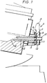
- a tilting electric arc furnace is provided with a taphole tube 2 of uniform bore, and a sliding gate valve mechanism 3.
- the floor of the furnace has a steep tap slope 4 leading to the taphole entrance.
- the furnace is shown tilted in the ready-to pour position, with the sliding gate valve open.
- a well or inlet nozzle 5 surrounded by a mounting plate 6.
- Attached to the mounting plate is a stationary top fixed plate 7.
- the hydraulic drive operating mechanism 8 comprises a hydraulic drive cylinder and piston rod (not shown) which moves the sliding gate 9 in a vertical direction between its open and closed positions.
- Attached to the sliding gate 9 is a collector nozzle 10, having a uniform bore, and a heat shield 11.
- the sliding gate In the closed position the sliding gate is raised so that the plate 12 blocks the exit to the well nozzle 5.
- the gate is raised when the furnace has been emptied of the required amount of liquid metal, or when furnace slag is sighted in the tap ladle.
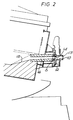
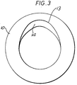
- FIG. 2 An embodiment of the invention is shown in Figure 2, where the reference numerals have the same significance as in Figure 1. It will be observed that the bore of the collector nozzle 10 has a vertically offset enlargement 13 which extends for the full length of the collector nozzle bore, apart from a small lead-in portion 14. In addition, the floor of the furnace has a longer, more gentle and uniform tap slope 15 having an angle of slope of 20° leading to the entrance to the taphole tube. The taphole tube bore 16 has a slight taper, its diameter decreasing slightly from entrance to exit. The shape of the offset bore of the collector nozzle can readily be seen from Figure 3.
- the furnace In operation, at the end of the refining stage, the furnace is tilted and the sliding gate carrying the collector nozzle 10 is lowered to the open position. Molten metal then passes through the tap hole tube 2 and the collector nozzle 10 and is received, for example, in a ladle. It is found that the furnace according to the invention provides a much more uniform metal stream with far less splashing and turbulence than the prior art arrangement.
- Prior art tilting electric arc furnaces having sliding gate taphole valves are readily converted to the new design of the invention by the provision of a new gate set, comprising various refractory components including a refractory collector nozzle according to the invention, a fixed plate, a sliding plate and an inlet nozzle.
- Gate sets are regularly supplied by the manufacturers of sliding gate taphole valves for the replacement of worn components.
- the invention is applicable to a wide range of metal refining processes, but is particularly useful in the production of high carbon alloy and stainless steels requiring tight analytical tolerances and high cleanliness.
Abstract
Description
- This invention relates to an improved apparatus and method for pouring molten metal from a furnace or converter, and more particularly to an improved furnace or converter tap hole design.
- Tilting electric arc furnaces, for example as used in steel manufacture, are provided with a taphole through which an oxygen lance can be inserted and from which the molten metal passes when the furnace is tilted at the end of the melting process. Traditionally the molten metal is poured into a trough, or launder, accompanied by a quantity of slag which becomes unavoidably entrained in the metal stream. To overcome the problem of slag contamination, it has recently been proposed to provide the taphole with a hydraulically operated sliding gate valve mechanism which provides a positive shut-off for the metal stream at the end of the pouring step and effectively prevents the slag, which floats on the surface of the metal, from entering the ladle. Such a device is, for example, supplied by Flogates Limited under the name FloCon Model 12800 Tap Hole Valve, and incorporates a collector nozzle.
- The sliding gate taphole valve works well in practice, but, due to the extra length of taphole required to accommodate the valve mechanism and collector nozzle in certain types of furnaces, problems can arise due to turbulence in the metal stream, which adopts a jagged appearance and is difficult to pour accurately. Efforts to eliminate this problem have hitherto proved unsuccessful.
- We have now discovered that an improved metal stream which is smoother and less turbulent can be produced by providing the taphole and/or collector nozzle with an offset bore enlargement. The reason for the improvement in flow is not entirely understood, but may result from an improved ability of dissolved gases to escape from the metal stream during its passage through the taphole and/or collector nozzle.
- According to one aspect of the present invention there is provided a tilting electric arc furnace or converter having a taphole and/or collector nozzle which is provided, for at least a portion of its length, with an offset bore enlargement.
- The invention also comprises a method of pouring molten metal from a furnace or converter, in particular a tilting electric arc furnace, in which the metal is discharged through a taphole and/or collector nozzle which is provided, for at least a portion of its length, with an offset bore enlargement.
- In another aspect, the invention also provides a sliding gate taphole valve provided with a collector nozzle, the collector nozzle being provided, for at least a portion of its length, with an offset bore enlargement, a collector nozzle having an offset bore enlargement for use therewith, and a gate set incorporating such a collector nozzle.
- The invention is particularly applicable to tilting electric arc furnaces and will henceforth be more specifically described with reference thereto. In addition, although it is envisaged that the principle of the offset bore enlargement could be applied to the taphole tube itself, to the collector nozzle, or to both the taphole tube and the collector nozzle, it is usually simpler and more convenient to form the offset bore enlargement solely in the bore of the collector nozzle. The invention will thus be further exemplified with respect to such a collector nozzle having an offset bore enlargement but is not to be taken as limited thereto.
- The collector nozzle can be fixed immovably to the furnace or converter but is preferably attached to the sliding gate of a sliding gate valve mechanism of the type previously mentioned.
- The enlargement to the collector nozzle bore is offset from the central line of the bore and is usually, though not necessarily exclusively, an enlargement to the vertical height of the bore. Other directions of the enlargement may also be possible, and the invention also includes the possibility of more than one such enlargement offset in different and possibly opposite directions from the central line. However, preferably the height of the bore is greater than the width, and for example the bore may be of ovoid, elliptical or any other suitable non-circular cross-sectional shape. Preferably the enlargement to the collector nozzle is achieved by simply increasing the height of the bore by, for example, from 10 to 20% of the diameter. The offset bore enlargement may extend for only a short distance, but preferably it extends for substantially the full length of the collector nozzle. Preferably the offset bore enlargement extends from the exit end of the collector nozzle towards the furnace, and most preferably it extends for the full length of the collector nozzle, apart from a small lead-in portion at the furnace end.
- As an example, if the bore is say 6 inches (15.24cm) in diameter, a suitable height increase would be 1 inch (2.54cm), giving a roughly ovoid cross-section. The length of the bore which is enlarged in this fashion is usually at least 15 inches (38.1cm), measured from the exit of the collector nozzle, and preferably from 15 to 25 inches (38.1 to 63.5cm).
- It has also been discovered than an improvement in stream quality can be obtained by providing the sloping floor of the furnace or converter with a gentle tap slope of 20° or less leading up to the entrance to the taphole. The combination of this feature with the offset bore enlargement of the collector nozzle has been found to give excellent results in practice.
- The bore of the taphole can be straight, but preferably it is slightly tapered towards the end leading to the collector nozzle. This also has been found to give improved results in certain circumstances.
- An embodiment of the invention will now be described with reference to the accompanying Drawings in which:
- Figure 1 shows, in sectional side elevation, a prior art arrangement of a tilting electric arc furnace having a taphole fitted with a sliding gate valve mechanism;
- Figure 2 shows, also in sectional side elevation, a tilting electric arc furnace according to the invention having a sliding gate valve mechanism and a collector nozzle with an offset bore enlargement; and
- Figure 3 shows an end elevation of the collector nozzle of figure 2, looking into the furnace.
- Referring now to Figure 1, a tilting electric arc furnace is provided with a taphole tube 2 of uniform bore, and a sliding gate valve mechanism 3. The floor of the furnace has a steep tap slope 4 leading to the taphole entrance. The furnace is shown tilted in the ready-to pour position, with the sliding gate valve open. At the exit to the taphole tube is a well or inlet
nozzle 5 surrounded by a mounting plate 6. Attached to the mounting plate is a stationary top fixed plate 7. - The hydraulic drive operating mechanism 8 comprises a hydraulic drive cylinder and piston rod (not shown) which moves the sliding gate 9 in a vertical direction between its open and closed positions. Attached to the sliding gate 9 is a
collector nozzle 10, having a uniform bore, and a heat shield 11. In the closed position the sliding gate is raised so that theplate 12 blocks the exit to thewell nozzle 5. The gate is raised when the furnace has been emptied of the required amount of liquid metal, or when furnace slag is sighted in the tap ladle. - An embodiment of the invention is shown in Figure 2, where the reference numerals have the same significance as in Figure 1. It will be observed that the bore of the
collector nozzle 10 has a verticallyoffset enlargement 13 which extends for the full length of the collector nozzle bore, apart from a small lead-inportion 14. In addition, the floor of the furnace has a longer, more gentle anduniform tap slope 15 having an angle of slope of 20° leading to the entrance to the taphole tube. Thetaphole tube bore 16 has a slight taper, its diameter decreasing slightly from entrance to exit. The shape of the offset bore of the collector nozzle can readily be seen from Figure 3. - In operation, at the end of the refining stage, the furnace is tilted and the sliding gate carrying the
collector nozzle 10 is lowered to the open position. Molten metal then passes through the tap hole tube 2 and thecollector nozzle 10 and is received, for example, in a ladle. It is found that the furnace according to the invention provides a much more uniform metal stream with far less splashing and turbulence than the prior art arrangement. - Prior art tilting electric arc furnaces having sliding gate taphole valves are readily converted to the new design of the invention by the provision of a new gate set, comprising various refractory components including a refractory collector nozzle according to the invention, a fixed plate, a sliding plate and an inlet nozzle. Gate sets are regularly supplied by the manufacturers of sliding gate taphole valves for the replacement of worn components.
- The invention is applicable to a wide range of metal refining processes, but is particularly useful in the production of high carbon alloy and stainless steels requiring tight analytical tolerances and high cleanliness.
Claims (21)
- A tilting electric arc furnace or converter having a taphole (2) and/or a collector nozzle (10), which is provided, for at least a portion of its length, with an offset bore enlargement (13).
- A furnace according to Claim 1, in which the furnace is a tilting electric arc furnace and the offset bore enlargement is formed solely in the collector nozzle.
- A furnace according to Claim 2, in which the collector nozzle is attached to the sliding gate (9) of a sliding gate valve mechanism (3).
- A furnace according to Claim 2 or 3, in which the offset bore enlargement is an enlargement to the vertical height of the bore of the collector nozzle.
- A furnace according to Claim 4, in which the height of the bore is increased by from 10 to 20% of the diameter of the bore.
- A furnace according to any of Claims 2 to 5, in which the bore enlargement extends from the exit end of the collector nozzle.
- A furnace according to Claim 6, in which the length of the bore having the enlargement is from 15 to 25 inches (38.1 to 63.5 cms).
- A furnace according to any of Claims 2 to 7, in which the bore enlargement extends substantially for the full length of the collector nozzle.
- A furnace or converter according to any of the preceding claims, in which the floor of the furnace or converter is provided with a tap slope (15) of 20 degrees or less leading up to the entrance to the taphole tube.
- A furnace or converter according to any of the preceding claims, in which the bore (16) of the taphole tube is slightly tapered towards its end leading to the collector nozzle.
- A method of pouring molten metal from a tilting electric arc furnace or converter, in which the metal is discharged through a taphole (2) and/or collector nozzle (10) which is provided, for at least a portion of its length, with an offset bore enlargement (13).
- A method according to Claim 11, in which the metal is discharged through a sliding gate valve (3) and a collector nozzle having an offset bore enlargement is attached to the sliding gate (9).
- A method according to Claim 12, in which there is used a collector nozzle having any one of the features of Claims 2,4,5,6,7, or 8.
- A method according to any of Claims 11 to 13, in which the floor of the furnace or converter is provided with a tap slope (15) of 20 degrees or less leading up to the entrance of the taphole tube.
- A method according to any of Claims 11 to 14, in which the bore (16) of the taphole tube is slightly tapered towards its end leading to the collector nozzle.
- A sliding gate taphole valve (3) provided with a collector nozzle (10), the collector nozzle being provided, for at least a portion of its length, with an offset bore enlargement (13).
- A valve according to Claim 16, provided with a collector nozzle having any one of the features of Claims 2,4,5,6,7, or 8.
- A collector nozzle (10) for a tilting electric arc furnace or converter having an offset bore enlargement (13).
- A collector nozzle according to Claim 18, having any one of the features of Claims 2,4,5,6,7, or 8.
- A collector nozzle according to Claim 18, which is adapted to be attached to the sliding gate of a sliding gate valve mechanism.
- A gate set for a sliding gate taphole valve (3) comprising a collector nozzle (10) according to any one of claims 18 to 20.
Applications Claiming Priority (3)
| Application Number | Priority Date | Filing Date | Title |
|---|---|---|---|
| GB919108038A GB9108038D0 (en) | 1991-04-16 | 1991-04-16 | Improved taphole design and method |
| GB91080382 | 1991-04-16 | ||
| PCT/GB1992/000602 WO1992018818A1 (en) | 1991-04-16 | 1992-04-03 | Taphole design and pouring method |
Publications (2)
| Publication Number | Publication Date |
|---|---|
| EP0583253A1 EP0583253A1 (en) | 1994-02-23 |
| EP0583253B1 true EP0583253B1 (en) | 1997-01-08 |
Family
ID=10693331
Family Applications (1)
| Application Number | Title | Priority Date | Filing Date |
|---|---|---|---|
| EP92907349A Expired - Lifetime EP0583253B1 (en) | 1991-04-16 | 1992-04-03 | Taphole design and pouring method |
Country Status (12)
| Country | Link |
|---|---|
| US (1) | US5524119A (en) |
| EP (1) | EP0583253B1 (en) |
| JP (1) | JPH06510112A (en) |
| AT (1) | ATE147501T1 (en) |
| AU (1) | AU661300B2 (en) |
| CA (1) | CA2108578A1 (en) |
| DE (1) | DE69216604D1 (en) |
| ES (1) | ES2097906T3 (en) |
| GB (1) | GB9108038D0 (en) |
| PL (1) | PL173305B1 (en) |
| WO (1) | WO1992018818A1 (en) |
| ZA (1) | ZA922404B (en) |
Families Citing this family (7)
| Publication number | Priority date | Publication date | Assignee | Title |
|---|---|---|---|---|
| LU88253A1 (en) * | 1993-04-30 | 1994-12-01 | Wurth Paul Sa | Tapping hole for a shaft furnace, especially a blast furnace |
| DE19628339C1 (en) * | 1996-07-13 | 1998-01-08 | Didier Werke Ag | converter |
| EP0931839A1 (en) * | 1997-12-24 | 1999-07-28 | SNC Astori et Ferretti O.T.I. Etincelle | Process for manufacturing of steel ingots with high purity |
| BE1019269A3 (en) * | 2010-04-02 | 2012-05-08 | Belgoprocess N V | TIPABLE OVEN. |
| CN102269523B (en) * | 2011-06-22 | 2014-04-09 | 安徽众源新材料股份有限公司 | Improved melting furnace |
| CN102401568A (en) * | 2011-11-14 | 2012-04-04 | 山西省高平市泫氏铸业有限公司 | Medium frequency electric furnace mouth |
| CN113523237B (en) * | 2021-07-19 | 2022-04-08 | 湖北航特装备制造股份有限公司 | Low-pressure casting system for aluminum alloy auxiliary frame production |
Family Cites Families (15)
| Publication number | Priority date | Publication date | Assignee | Title |
|---|---|---|---|---|
| US644510A (en) * | 1899-11-21 | 1900-02-27 | Frederick A Lehmann | Process of electrical reduction. |
| US1338881A (en) * | 1920-02-13 | 1920-05-04 | Stock Guy James | Production of iron in an electric furnace |
| US1944611A (en) * | 1930-01-13 | 1934-01-23 | American Rolling Mill Co | Nozzle for pouring molten metal |
| US2755327A (en) * | 1948-05-26 | 1956-07-17 | Ajax Engineering Corp | Device for the discharge of molten metal |
| US2937789A (en) * | 1953-10-16 | 1960-05-24 | Ajax Magnethermic Corp | Controlled metal dispensing |
| US4181812A (en) * | 1977-03-28 | 1980-01-01 | Asea Aktiebolag | Iron oxide melt reduction furnace and method |
| DE2918344A1 (en) * | 1979-05-07 | 1980-11-20 | Metacon Ag | SLIDING CLOSURE FOR THE TAPPING CHANNEL OF A METALLURGICAL OVEN OR CONTAINER |
| AT387039B (en) * | 1981-02-05 | 1988-11-25 | Veitscher Magnesitwerke Ag | TAPPING DEVICE FOR CONVERTER |
| GB2097901B (en) * | 1981-05-01 | 1985-02-13 | Uss Eng & Consult | Valve suitable for controlling teeming from furnace tapholes |
| DE3231316A1 (en) * | 1982-08-23 | 1984-04-12 | Leybold-Heraeus GmbH, 5000 Köln | METHOD AND DEVICE FOR CONTROLLING THE POURING OF A MEL FROM A MELT CONTAINER WITH A BOTTOM OPENING |
| AT381788B (en) * | 1984-09-18 | 1986-11-25 | Voest Alpine Ag | ELECTRIC MELTING STOVE |
| US4785979A (en) * | 1987-07-28 | 1988-11-22 | Casteel Technology Associates, Ltd. | Flow control nozzle for bottom-pour ladles |
| EP0352353B1 (en) * | 1988-07-28 | 1991-05-08 | INTRACON Handelsgesellschaft für Industriebedarf mbH | Ladle nozzle brick for a closure device of a ladle |
| US5240231A (en) * | 1990-07-31 | 1993-08-31 | Industrial Maintenance And Contract Services Limited Partnership | Slag control system |
| US5173243A (en) * | 1990-07-31 | 1992-12-22 | Industrial Maintenance And Contract Services Limited Partnership | Slag control method and apparatus |
-
1991
- 1991-04-16 GB GB919108038A patent/GB9108038D0/en active Pending
-
1992
- 1992-04-02 ZA ZA922404A patent/ZA922404B/en unknown
- 1992-04-03 CA CA002108578A patent/CA2108578A1/en not_active Abandoned
- 1992-04-03 EP EP92907349A patent/EP0583253B1/en not_active Expired - Lifetime
- 1992-04-03 AT AT92907349T patent/ATE147501T1/en not_active IP Right Cessation
- 1992-04-03 JP JP4507171A patent/JPH06510112A/en active Pending
- 1992-04-03 ES ES92907349T patent/ES2097906T3/en not_active Expired - Lifetime
- 1992-04-03 WO PCT/GB1992/000602 patent/WO1992018818A1/en active IP Right Grant
- 1992-04-03 US US08/137,041 patent/US5524119A/en not_active Expired - Fee Related
- 1992-04-03 PL PL92301009A patent/PL173305B1/en unknown
- 1992-04-03 DE DE69216604T patent/DE69216604D1/en not_active Expired - Lifetime
- 1992-04-03 AU AU14643/92A patent/AU661300B2/en not_active Ceased
Also Published As
| Publication number | Publication date |
|---|---|
| AU1464392A (en) | 1992-11-17 |
| US5524119A (en) | 1996-06-04 |
| PL173305B1 (en) | 1998-02-27 |
| JPH06510112A (en) | 1994-11-10 |
| DE69216604D1 (en) | 1997-02-20 |
| AU661300B2 (en) | 1995-07-20 |
| WO1992018818A1 (en) | 1992-10-29 |
| CA2108578A1 (en) | 1992-10-17 |
| GB9108038D0 (en) | 1991-06-05 |
| EP0583253A1 (en) | 1994-02-23 |
| ATE147501T1 (en) | 1997-01-15 |
| ES2097906T3 (en) | 1997-04-16 |
| ZA922404B (en) | 1992-12-30 |
Similar Documents
| Publication | Publication Date | Title |
|---|---|---|
| US4699654A (en) | Melting furnace and method for melting metal | |
| ATE186751T1 (en) | METHOD AND DEVICE FOR OPERATING A DOUBLE VESSEL ARC FURNACE | |
| EP0583253B1 (en) | Taphole design and pouring method | |
| KR100676656B1 (en) | Treatment for improving the castability of aluminium killed continuously cast steel | |
| CN212610759U (en) | Converter slide blows argon tapping gate valve equipment | |
| JP4351607B2 (en) | Slag closing jig and method of using the same | |
| Way | Cleanness, castability, and surface quality of formable sheet steels | |
| Kamaraj et al. | State of the art control measures for aluminium fade and SEN clogging during steelmaking operations | |
| US4726033A (en) | Process to improve electric arc furnace steelmaking by bottom gas injection | |
| Szekeres | Review of strand casting factors affecting steel product cleanliness | |
| JPH06218504A (en) | Tundish refining method | |
| CN1443866A (en) | Production process of aluminium-containing steel | |
| PL92986B1 (en) | ||
| CN104975131B (en) | The method that the quantity of slag is controlled under converter smelting half steel | |
| CN220246178U (en) | Steelmaking furnace capable of preventing molten iron from splashing | |
| CN109355458A (en) | A kind of oxygen-enriched side-blowing melting converter | |
| JPH0518669A (en) | Terminal brick for hearth tap hole of electric furnace | |
| KR20020016818A (en) | Discharge channel for melting furnaces and pouring ladles | |
| CN117086298A (en) | Ladle for reducing molten steel oxidation and method for reducing molten steel oxidation | |
| JP2002336957A (en) | Sliding nozzle of metallurgic vessel, and deposit removing method | |
| RU1786096C (en) | Method of gas-dynamic separation of slag from molten metal | |
| RU2084540C1 (en) | Cooled tuyere for blowing melt | |
| RU1782240C (en) | Method for melting corrosion-resistant steel in an electric arc furnace | |
| Aydemir | Use of aluminium dross for slag treatment in secondary steelmaking to decrease amount of reducible oxides in ladle furnace | |
| CN112226567A (en) | Converter sliding plate slag blocking accident prevention operation control method |
Legal Events
| Date | Code | Title | Description |
|---|---|---|---|
| PUAI | Public reference made under article 153(3) epc to a published international application that has entered the european phase |
Free format text: ORIGINAL CODE: 0009012 |
|
| 17P | Request for examination filed |
Effective date: 19931125 |
|
| AK | Designated contracting states |
Kind code of ref document: A1 Designated state(s): AT BE DE ES FR GB IT SE |
|
| RAP1 | Party data changed (applicant data changed or rights of an application transferred) |
Owner name: FLOGATES LIMITED |
|
| 17Q | First examination report despatched |
Effective date: 19951023 |
|
| GRAG | Despatch of communication of intention to grant |
Free format text: ORIGINAL CODE: EPIDOS AGRA |
|
| GRAH | Despatch of communication of intention to grant a patent |
Free format text: ORIGINAL CODE: EPIDOS IGRA |
|
| GRAH | Despatch of communication of intention to grant a patent |
Free format text: ORIGINAL CODE: EPIDOS IGRA |
|
| GRAA | (expected) grant |
Free format text: ORIGINAL CODE: 0009210 |
|
| AK | Designated contracting states |
Kind code of ref document: B1 Designated state(s): AT BE DE ES FR GB IT SE |
|
| PG25 | Lapsed in a contracting state [announced via postgrant information from national office to epo] |
Ref country code: IT Free format text: LAPSE BECAUSE OF FAILURE TO SUBMIT A TRANSLATION OF THE DESCRIPTION OR TO PAY THE FEE WITHIN THE PRESCRIBED TIME-LIMIT;WARNING: LAPSES OF ITALIAN PATENTS WITH EFFECTIVE DATE BEFORE 2007 MAY HAVE OCCURRED AT ANY TIME BEFORE 2007. THE CORRECT EFFECTIVE DATE MAY BE DIFFERENT FROM THE ONE RECORDED. Effective date: 19970108 Ref country code: BE Effective date: 19970108 Ref country code: AT Effective date: 19970108 |
|
| REF | Corresponds to: |
Ref document number: 147501 Country of ref document: AT Date of ref document: 19970115 Kind code of ref document: T |
|
| REF | Corresponds to: |
Ref document number: 69216604 Country of ref document: DE Date of ref document: 19970220 |
|
| PG25 | Lapsed in a contracting state [announced via postgrant information from national office to epo] |
Ref country code: DE Effective date: 19970409 |
|
| REG | Reference to a national code |
Ref country code: ES Ref legal event code: FG2A Ref document number: 2097906 Country of ref document: ES Kind code of ref document: T3 |
|
| ET | Fr: translation filed | ||
| PLBE | No opposition filed within time limit |
Free format text: ORIGINAL CODE: 0009261 |
|
| STAA | Information on the status of an ep patent application or granted ep patent |
Free format text: STATUS: NO OPPOSITION FILED WITHIN TIME LIMIT |
|
| 26N | No opposition filed | ||
| PGFP | Annual fee paid to national office [announced via postgrant information from national office to epo] |
Ref country code: FR Payment date: 19990216 Year of fee payment: 8 |
|
| PGFP | Annual fee paid to national office [announced via postgrant information from national office to epo] |
Ref country code: SE Payment date: 19990305 Year of fee payment: 8 |
|
| PGFP | Annual fee paid to national office [announced via postgrant information from national office to epo] |
Ref country code: ES Payment date: 19990412 Year of fee payment: 8 |
|
| PG25 | Lapsed in a contracting state [announced via postgrant information from national office to epo] |
Ref country code: SE Free format text: LAPSE BECAUSE OF NON-PAYMENT OF DUE FEES Effective date: 20000404 Ref country code: ES Free format text: THE PATENT HAS BEEN ANNULLED BY A DECISION OF A NATIONAL AUTHORITY Effective date: 20000404 |
|
| EUG | Se: european patent has lapsed |
Ref document number: 92907349.2 |
|
| PG25 | Lapsed in a contracting state [announced via postgrant information from national office to epo] |
Ref country code: FR Free format text: LAPSE BECAUSE OF NON-PAYMENT OF DUE FEES Effective date: 20001229 |
|
| REG | Reference to a national code |
Ref country code: FR Ref legal event code: ST |
|
| REG | Reference to a national code |
Ref country code: GB Ref legal event code: IF02 |
|
| REG | Reference to a national code |
Ref country code: ES Ref legal event code: FD2A Effective date: 20020304 |
|
| PGFP | Annual fee paid to national office [announced via postgrant information from national office to epo] |
Ref country code: GB Payment date: 20040401 Year of fee payment: 13 |
|
| PG25 | Lapsed in a contracting state [announced via postgrant information from national office to epo] |
Ref country code: GB Free format text: LAPSE BECAUSE OF NON-PAYMENT OF DUE FEES Effective date: 20050403 |
|
| GBPC | Gb: european patent ceased through non-payment of renewal fee |
Effective date: 20050403 |