EP0583046A2 - Farbbandkassette und Druckerantrieb für das Farbband - Google Patents
Farbbandkassette und Druckerantrieb für das Farbband Download PDFInfo
- Publication number
- EP0583046A2 EP0583046A2 EP93301609A EP93301609A EP0583046A2 EP 0583046 A2 EP0583046 A2 EP 0583046A2 EP 93301609 A EP93301609 A EP 93301609A EP 93301609 A EP93301609 A EP 93301609A EP 0583046 A2 EP0583046 A2 EP 0583046A2
- Authority
- EP
- European Patent Office
- Prior art keywords
- ribbon
- stripper
- cartridge
- printer
- rollers
- Prior art date
- Legal status (The legal status is an assumption and is not a legal conclusion. Google has not performed a legal analysis and makes no representation as to the accuracy of the status listed.)
- Granted
Links
- 230000007246 mechanism Effects 0.000 claims abstract description 35
- 230000004044 response Effects 0.000 claims abstract description 5
- 230000008878 coupling Effects 0.000 claims 2
- 238000010168 coupling process Methods 0.000 claims 2
- 238000005859 coupling reaction Methods 0.000 claims 2
- 210000005069 ears Anatomy 0.000 description 2
- 238000003466 welding Methods 0.000 description 2
- 230000009471 action Effects 0.000 description 1
- 239000000853 adhesive Substances 0.000 description 1
- 230000001070 adhesive effect Effects 0.000 description 1
- 238000006073 displacement reaction Methods 0.000 description 1
- 230000008030 elimination Effects 0.000 description 1
- 238000003379 elimination reaction Methods 0.000 description 1
- 230000014759 maintenance of location Effects 0.000 description 1
- 239000000463 material Substances 0.000 description 1
- 230000004048 modification Effects 0.000 description 1
- 238000012986 modification Methods 0.000 description 1
- 230000009467 reduction Effects 0.000 description 1
Images





Classifications
-
- B—PERFORMING OPERATIONS; TRANSPORTING
- B41—PRINTING; LINING MACHINES; TYPEWRITERS; STAMPS
- B41J—TYPEWRITERS; SELECTIVE PRINTING MECHANISMS, i.e. MECHANISMS PRINTING OTHERWISE THAN FROM A FORME; CORRECTION OF TYPOGRAPHICAL ERRORS
- B41J33/00—Apparatus or arrangements for feeding ink ribbons or like character-size impression-transfer material
- B41J33/02—Ribbon arrangements
- B41J33/10—Arrangements of endless ribbons
-
- B—PERFORMING OPERATIONS; TRANSPORTING
- B41—PRINTING; LINING MACHINES; TYPEWRITERS; STAMPS
- B41J—TYPEWRITERS; SELECTIVE PRINTING MECHANISMS, i.e. MECHANISMS PRINTING OTHERWISE THAN FROM A FORME; CORRECTION OF TYPOGRAPHICAL ERRORS
- B41J32/00—Ink-ribbon cartridges
- B41J32/02—Ink-ribbon cartridges for endless ribbons
Definitions
- the present invention relates to ribbon cartridges containing an endless print ribbon for use in printers and drive systems for the ribbon cartridges forming part of the printer.
- the invention relates to a ribbon cartridge having component parts for transporting, guiding and storing the endless print ribbon and which parts are cooperable with a drive system mounted on the printer for driving the print ribbon, whereby the number of parts and, hence, the cost of the consumable ribbon cartridges are reduced.
- ribbon cartridges are consumable items discarded with use and replaced with fresh cartridges. Even in those ribbon cartridges containing a re-inker and which cartridges therefore have extended useful life, ultimately the cartridge is discarded and replaced.
- Such ribbon cartridges typically mount the ribbon drive system within the cartridge and which drive system is therefore discarded with the ribbon cartridge.
- These ribbon drive systems substantially increase the cost of the ribbon cartridge. Consequently, otherwise reusable drive system components are discarded and replaced with new cartridges likewise containing duplicate and otherwise reusable drive system components.
- the present invention provides a replaceable ribbon cartridge in the form of an elongated, generally rectilinear housing having ribbon entrance and exit arms projecting to one side of the housing at its opposite ends, respectively.
- the housing includes top, bottom and side walls which in part define a ribbon storage chamber which extends over a substantial majority of the length of the housing.
- the endless ribbon thus extends from the ribbon storage chamber, preferably through a mobius loop, and along the exit arm, passes out of the exit arm for spanning between the tips of the exit and entrance arms, and reenters the cartridge through the entrance arm for return to the storage chamber.
- the bottom wall of the cartridge has an opening which, when the cartridge is applied in overlying relation to the printer deck, receives the ribbon drive system which is mounted on the printer deck.
- the print ribbon of the cartridge spans across the opening in the bottom wall of the cartridge and the drive system, as described hereinafter, has a mechanism for engaging and disengaging the print ribbon enabling the cartridge to be placed on the printer for use and removed therefrom for replacement.
- the cartridge therefore serves to transport, guide and store the ribbon but does not contain a drive system for the ribbon.
- the cartridge contains a stripper which performs the twofold function of providing a wall at one end of the ribbon storage chamber for maintaining the ribbon in a folded, preferably random folded, condition, as well as providing stripper elements for stripping the ribbon from the rollers forming part of the printer-mounted drive system for the ribbon when the cartridge is loaded into the printer for use.
- the stripper is mounted for generally linear movement within the cartridge housing between a retracted position and a position locating the stripper elements adjacent the nip of the drive system rollers to strip the ribbon from the rollers and feed it into the storage chamber.
- the cartridge is therefore specifically formed to transport, guide and store the ribbon and to cooperate with a drive system forming part of the printer which serves to engage and drive the ribbon when the cartridge is loaded into the printer and to release the ribbon when the cartridge is removed from the printer for replacement.
- the ribbon cartridge hereof may or may not include a re-inker, depending upon the needs of the user of the cartridge and associated printer. Additionally, the cartridge is provided with a spoolerfor taking up slack in the ribbon spanning between the ends of the exit and entrance arms, thereby ensuring that the ribbon extending across the print mechanism, upon loading the cartridge into the printer, is straight and taut. It also simultaneously takes up slack in the ribbon spanning across the bottom opening in the cartridge to ensure, when the cartridge is loaded into the printer, that the ribbon will be engaged with the drive system.
- the spooler includes two parallel bars or pins carried by a manually rotatable device.
- the freely rotatable spooler also enables the ribbon to be unwrapped therefrom when the drive system is engaged and printing commences.
- the housing may be provided in the form of discrete top and bottom wall parts, with the side walls being carried by one or the other of those parts or, alternatively, portions of the side walls may form parts of the top and bottom wall parts, respectively.
- the ribbon entrance and exit arms also form portions of the top and bottom wall component parts.
- the top and bottom walls are configured to define the storage chamber for the ribbon upon assembly thereof and the bottom wall part has an opening for receiving the roller drive mechanism upon assembly of the cartridge and loading it into the printer.
- the top and bottom wall parts may be assembled and secured one to the other to form the ribbon cartridge by staking, ultrasonic welding of the plastic material or otherwise, as desired.
- a stripper which includes a pair of laterally spaced stripper elements defining a slot therebetween for receiving the ribbon when the assembled cartridge is loaded onto the printer.
- the stripper also has a pair of depending pins which are receivable through openings, preferably elongated slots, in the bottom wall part such that, when the stripper is assembled into the cartridge, the pins project through the slots for engagement by a drive mechanism whereby the stripper may be moved longitudinally within and along the cartridge upon assembly.
- Guide surfaces are provided on the stripper to facilitate this movement.
- Various other parts may be formed as integral or attachable elements to the top and bottom wall parts. For example, pins for mounting guide rollers for the ribbon may project from one or the other of the top or bottom wall parts.
- the spooler may be provided as a separable part for alignment with openings in both the top and bottom wall parts upon assembly such that the spooler can be manually rotated.
- the drive system is mounted on the printer deck and includes a control means for controllably displacing an idler roller toward and away from a drive roller between positions engaging the ribbon between the rollers and disengaging it from the rollers.
- the control means also linearly displaces a stripper actuating member engageable with the stripper in the cartridge upon loading the cartridge into the printer to move the stripper between its retracted and stripping positions.
- the drive system includes a base secured to the printer deck and mounting a drive roller connected to a drive motor within the printer.
- a lever is movably mounted on the base, preferably pivotally mounted, and carries an idler roller for movement toward and away from the drive roller.
- a spring biases the lever for movement in a direction tending to engage the idler roller against the drive roller.
- the lever also pivotally carries an underlying cam.
- the cam is rotatable by a crank arm and is cooperable with a pin mounted on the base for displacing the lever against the bias of the spring in a direction moving the idler roller away from the drive roller.
- the cam carries a detent surface which cooperates with the pin for detenting the lever in a retracted position spacing the idler roller from the drive roller to enable placement of the print ribbon between the spaced rollers when the cartridge is loaded into the printer.
- a stripper actuating member is slidably mounted on the printer deck and a stripper actuating member drive arm interconnects the cam and the stripper actuating arm.
- the actuating member has recesses for receiving pins which project downwardly from the stripper through elongated slots in the bottom wall of the cartridge such that the actuating member and stripper are engaged one with the other when the cartridge is loaded into the printer.
- the drive arm is connected to the cam such that, when the lever is in its retracted position spacing the idler roller from the drive roller, the actuating member is spaced and retracted from the rollers. It will be appreciated that this retracted position of the actuating member corresponds to the retracted position of the stripper in the cartridge.
- the cartridge is placed on the printer deck with the drive system of the printer being received into the confines of the cartridge housing through the opening in the bottom wall, the crank handle also being received through an opening through the top wall of the cartridge.
- the print ribbon is thus disposed between the spaced idler and drive rollers.
- the stripper and stripper actuating member are also engaged one with the other and lie in their retracted positions.
- the crank arm is then rotated to release the detenting cam and pin, enabling the spring to rotate the lever to engage the ribbon between the idler and drive rollers.
- crankarm also rotates the cam to pull the drive arm and, hence, the actuating member in a direction toward the rollers.
- This moves the stripper in the cartridge toward its operable position engaging the stripper elements in grooves on the idler and drive rollers.
- these stripper elements serve to strip the ribbon from the rollers and guide the ribbon into the storage chamber.
- the engagement of the stripper elements within grooves in the rollers also locks the cartridge against displacement from the printer deck.
- the crank arm when rotated to engage the ribbon between the rollers, is rotated into a position overlying the top wall of the cartridge housing and this also precludes removal of the cartridge from the printer deck.
- the crank arm is rotated so that the cam bears against the pin and rotates the lever against the spring bias to retract the idler roller from engagement with the ribbon and the drive roller. Simultaneously, the cam pushes the drive arm to move the actuating member away from the rollers and, consequently, the stripper in the cartridge is likewise moved away from the rollers. This withdraws the stripper elements from within the grooves of the idler and drive rollers, and aligns the crank arm with the openings through the top and bottom walls of the cartridge housing, enabling the cartridge to be moved from the printer deck.
- a ribbon cartridge for a printer having a ribbon drive mechanism including a pair of rollers for engaging a print ribbon therebetween, comprising an elongated cartridge housing having top, bottom, and side walls and a pair of arms projecting to one side of the housing adjacent to opposite ends, the walls in part defining a storage chamberfor receiving and storing the print ribbon, and the arms defining entrance and exit paths, respectively, for receiving the ribbon for delivery to the storage chamber and supplying the ribbon from the storage chamber for spanning between the arms.
- the bottom wall has an opening for receiving the pair of rollers substantially within the confines of the cartridge housing when the cartridge is loaded into the printer.
- a stripper having stripper elements is carried by the cartridge housing for movement between a first retracted position and a second extended position with the stripper elements disposed adjacent the pair of rollers for stripping the ribbon from the rollers.
- the bottom wall of the housing includes a pair of openings having an extent in the direction of the housing substantially at least equal to the range of movement of the stripper in the cartridge between the first and second positions.
- the stripper includes a pair of pins projecting through the openings below the bottom wall for engagement of at least one pin thereof by a drive carried by the printer for displacing the stripper from one of the first and second positions into the other of t he first and second positions.
- a printer having a printer deck for mounting a printer cartridge containing print ribbon, a drive mechanism for the print ribbon, comprising drive and idler rollers carried by the printer and projecting from the printer deck.
- a lever carries the idler roller and is mounted for movement on the printer deck for moving the idler roller laterally toward and away from the drive roller.
- Means for moving the lever between a first position for engaging the print ribbon between the rollers and a second position spacing the idler roller from the drive roller, to- getherwith means for biasing the lever for movement into one of the first and second positions are provided.
- Means for detenting the lever in the other of said first and second positions, as well as control means for displacing the lever from the detented position enabling the lever for movement toward the one position are also provided.
- a ribbon stripper actuating member engages the ribbon stripper in the cartridge and is carried by the printer deck for movement toward and away from the rollers.
- An arm interconnects the member and the moving means such that the member is movable toward and away from the rollers in response to movement of the idler gear toward and away from the drive roller, respectively.
- a parts kit for assembly into a ribbon cartridge for a printer having a ribbon drive mechanism including a pair of rollers for engaging a ribbon therebetween, comprising a top wall part having portions for defining in part a storage chamber for a ribbon and a bottom wall part having portions for defining in part the storage chamber for the ribbon, the bottom wall part having an opening for receiving the ribbon drive mechanism upon loading the assembled cartridge into the printer.
- One of the top and bottom wall parts includes portions defining at least in part ribbon entrance and ribbon exit arms, the top and bottom wall parts being adapted for assembly one with the other to form the ribbon cartridge with the portions of the top and bottom wall parts defining a storage chamber for the ribbon.
- a stripper is provided for assembly within the cartridge, the stripper including a pair of laterally spaced stripper elements for stripping ribbon from the rollers and defining a slot therebetween for receiving ribbon upon assembly of the kit to form the cartridge and loading thereof into the printer, the stripper having guides for mounting the stripper within the cartridge upon its assembly for movement in a direction toward and away from the bottom opening and having at least one pin projecting therefrom and through the bottom wall part for engagement by the drive mechanism upon loading the assembled cartridge into the printer.
- a stripper for location in a ribbon cartridge for stripping ribbon from drive rollers and guiding the ribbon into a storage chamber of the cartridge comprising a stripper body for generally horizontal slidable movement within the cartridge toward and away from the drive rollers and having a laterally extending wall and a pair of laterally spaced stripper elements projecting forwardly from the stripper body and defining a forwardly extending slot for receiving ribbon therebetween.
- Upstanding wall portions project from the laterally extending wall and are located rearwardly of the stripper elements forengaging ribbon in the storage chamber of the cartridge on the side of the stripper body opposite the stripper elements, the wall portions having an opening therebetween for receiving ribbon from the slot for entry into the storage chamber.
- a pair of pins project downwardly from the laterally extending wall adjacent its opposite ends and for termination below the stripper elements.
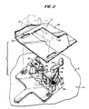
- ribbon cartridge 10 constructed in accordance with the present invention, for mounting on the printer deck 12 of a printer, and overlying relation to a drive mechanism, generally designated 14, also constructed in accordance with the present invention.
- ribbon cartridge 10 comprises a generally rectilinear housing 16 having top and bottom walls 18 and 20, respectively, and side walls 22. Housing 16 also includes ribbon exit and entrance arms 24 and 26, respectively. It will be appreciated that a ribbon R spans between the distal ends of the ribbon exit and entrance arms 24 and 26, respectively, and comprises an endless ribbon driven by drive mechanism 14 when cartridge 10 is loaded into the printer.
- Housing 16 as illustrated in Figures 3 and 4 includes a storage chamber 28 for storing the endless ribbon R, preferably in a random fashion, and which storage chamber 28 extends the majority of the length of housing 16. Adjacent the end of storage chamber 28 and exit arm 24, there is provided an inverting mechanism, i.e., a mobius loop, not shown, for inverting the ribbon drawn from storage chamber 28. It will be appreciated that drive mechanism 14 removes (pulls) ribbon R from storage chamber 28, inverts the ribbon, passes it into exit arm 24, and pulls the ribbon from the exit arm 24 to span tightly between arms 24 and 26 along a print line of the printer and then for entry into entry arm 26 and storage at the opposite end of storage chamber 28.
- inverting mechanism i.e., a mobius loop
- upperwall 18 of housing 16 has an opening 30, and lower wall 20 has an opening 32 in registration with the upper wall opening 30.
- the openings are provided to receive drive mechanism 14 when the cartridge 10 is loaded into the printer such that drive mechanism 14 lies within the confines of cartridge 10.
- entrance arm 26 there is provided a rotary device 34 for spooling the ribbon R, prior to mounting the cartridge in the printer, to draw the ribbon taut between the distal ends of the exit and entrance arms 24 and 26 and also across the bottom opening 32.
- the spooling device is best illustrated in Figure 27 and includes a pair of disks 36 and 38 connected one to the other by spaced pins or bars 40. Stub shafts 42 are provided on the opposite ends of the rotary device 34 and the ribbon R is threaded between the bars 40.
- ribbon R extends from the rotary device 34 about a plurality of rollers 46, 47 and 50 and spans between the upper and lower openings 30 and 32, respectively, in the top and bottom walls of the cartridge housing 16.
- the ribbon extends through a stripper 48 which, in conjunction with the drive system, disposes the ribbon into the storage chamber 28.
- a re-inking device 51 which may or may not be used in the cartridge, depending upon the user's needs. It will be appreciated that re-inkers per se are old in the art and that the ribbon R would be rerouted otherwise than as shown to engage the re-inker.
- the bottom wall 20 of housing 16 is provided with a pair of slots 52 adjacent respective opposite side walls 22 for slidably mounting the stripper 48.
- Stripper 48 extends transversely between side walls 22 and includes, as illustrated best in Figures 5-8, an upper wall 54, laterally spaced, angularly related depending side walls 56, and a pair of laterally extending horizontal intermediate walls 58 carrying downwardly projecting pins 60 adjacent opposite sides of stripper 48, with one side of the stripper 48 having an additional side wall 62.
- a plurality of paired stripper elements 64 are vertically spaced one from the other and define a feed slot 66 for feeding ribbon Rfrom drive mechanism 14 into storage chamber 28.
- Upper wall 54 includes a rearwardly projecting tongue 68 and a forwardly projecting tab 70 for overlying the edge of the ribbon as the ribbon proceeds through the rollers of the drive mechanism and into slot 66.
- a pin 72 projects upwardly from wall 54 and is received through a slot, not shown, in the upper wall of the cartridge.
- stripper 48 is slidably disposed in cartridge housing 16 with pins 60 engaging through slots 52 in bottom wall 20. Consequently, stripper 48 is linearly movable between positions retracted from the bottom opening 32 and, hence, the drive mechanism 14, when received through bottom opening 32, and extended in a ribbon engaged position adjacent the rollers of the drive system, to be described.
- the stripper 48 is maintained in its retracted position by a pair of flat leaf springs 74 ( Figures 3 and 4) engaging between abutments on side walls 22 and side walls 56 of stripper 48.
- springs 74 flex in the opposite direction biasing the stripper into its extended engaged position illustrated in Figure4.
- stripper48 is detented in both positions.
- the various elements of the cartridge as described above may be provided in a kit of parts.
- the top wall, bottom wall, configured as described, the stripper, the various rollers, and spooler may be provided as separate discrete parts by a manufacturer for later assembly into the cartridge with the ribbon in the storage chamber. Staking, welding, adhesive or other forms of securement may be used to maintain the parts in their assembled condition.
- drive system 14 is illustrated mounted on printer deck 12 and includes a frame or base 80 mounting a drive roller 82 fixed for rotation by a drive motor, not shown, within the printer.
- an idler roller 84 mounted on a lever 86 movable, preferably pivotable, about the axis of a pin 88 between positions wherein idler roller 84 is retracted and spaced from the drive roller, as illustrated in Figure 3, and in engagement with the ribbon R disposed between the drive roller and idler roller, as illustrated in Figure 4.
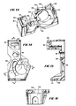
- the various parts of the drive mechanism as illustrated in Figures 13-25, will be described.
- the base frame 80 is secured to printer deck 12 and includes a lower bearing 90 (Figure 13) formount- ing the drive pin 92 carrying drive roller 82.
- a bearing cap 92 having a bearing 94 is secured by screw 95 on a mount 96 of base 80, with the lip 98 being received in a slot 100.
- the drive pin 92 is carried by bearings 90 and 94.
- FIG 13 there is illustrated a bearing 102 for the pin 88 carrying-lever 86.
- Adjacent bearing 82 is an upstanding pin 104 for cooperation with a cam 136, described hereinafter.
- Base 80 also includes an opening 106 between its upper and lower sides and has an upstanding end wall 108 with a recess 110 for mounting one end of a helical coil spring 112.
- lever 86 includes upper and lower lever arms 114 and 116 connected together by a sleeve 118 at one end of the lever for receiving pin 88 whereby the lever is mounted for pivotal movement.
- lever arms 114 and 116 mount aligned projecting ears 118 and 120, respectively, which, in turn, mount the pin 122 carrying idler roller 84.
- both the idler roller 84 and drive roller 82 are centrally recessed to provide annular grooves 122 and 124, respectively.
- lever 86 is provided with an opening 126 on a side thereof opposite ears 118 and 120 for receiving the other end of coil spring 112.
- spring 112 biases lever 86 toward the engaged position of the ribbon between the two rollers.
- Lever 86 also carries a bore 130 spaced from its axis of rotation about bearing 102.
- a pin 132 is disposed in bore 130 and mounts a crank handle 134 at its upper end for rotating the pin 132.
- the lower end of pin 132 carries a cam 136 illustrated in Figures 25 and 26.
- Cam 136 is rotatable with lever 86 about bearing 102 and is itself rotatable about the axis of bore 130 by rotation of crank arm 134.
- Cam 136 is disposed in the opening 106 and bears on a stepped portion 138 of base 80.
- Cam 136 includes a cam surface 140 eccentric to its axis of rotation and which cam surface 140 includes a detenting surface 142 for engagement with pin 104 ( Figure 13).
- cam 136 Also projecting from the underside of cam 136 is a drive pin 144 connecting with a drive arm 146 ( Figure 11) for displacing a stripper actuating member 148 upon rotation of cam 136, as described hereinafter.
- Aslot 149 is formed along the underside of base 80 for receiving the arm 146 in engagement with drive pin 144.
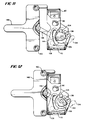
- drive mechanism 14 also includes a stripper actuating member 148 which is slidable linearly along the printer deck toward and away from rollers 82 and 84.
- Member 148 has a pair of recesses 150 along its opposite sides for receiving the pins 60 of stripper 48.
- arm 146 is pivoted to member 148 and drives member 148 between the retracted and extended positions, illustrated in Figures 11 and 12, respectively. It will be appreciated that when pins 60 engage recesses 150, movement of the stripper actuating member 148 causes following movement of stripper 48 toward and away from the rollers.
- the cartridge 10 is supplied with the stripper held in its retracted position by springs 74. It will be appreciated that, in such condition, the endless ribbon R is gathered and compressed in a random manner in storage compartment 28 with a portion of the ribbon extending between arms 24 and 26. To properly position the ribbon between the arms in the printer, any slack in that ribbon is taken up by twisting the rotary device 34 in either direction. Additionally, any slack in the ribbon between stripper48 and rotary device 34 is simultaneously taken up, thereby straightening the ribbon between stripper 48 and the first roller 50.
- cartridge 10 With the drive mechanism 14 disposed in its open position as illustrated in Figure 3, cartridge 10 is then placed on the printer deck 12 and receives drive mechanism 14 through its bottom opening 32.
- crank handle 134 projects through top opening 30 of the top wall 30 of the cartridge.
- the pins 60 of stripper 48 engage in the recesses 150 of stripper actuating member 148.
- cam 136 has previously been rotated such that cam detenting surface 142 bears against pin 104 of base 80, preventing spring 112 from pivoting lever 86 from its first retracted position ( Figure 3) into its second engaged position ( Figure 4) with idler roller 84 engaging the ribbon against drive roller 82.
- crank handle 134 To engage the ribbon, crank handle 134 is rotated, for example, in a counterclockwise direction as illustrated in Figure 3, into the position illustrated in Figure 4.
- detent surface 142 is removed from engagement with pin 104 and cam surface 140 bears along pin 104 from its high surface adjacent detent surface 142 to a low surface, enabling spring 112 to rotate lever 86 in a clockwise direction as seen in comparing Figures 3 and 4, moving idler roller 84 toward drive gear 82.
- stripper elements 64 in this advanced position of stripper48 moved into the grooves 122 and 124 of the rollers and also straddle the rollers at their upper and lower ends.
- the stripper elements are thus in position to strip the ribbon passing through the slot 66 from the rollers as the drive gear rotates to advance the ribbon pastthe rollers and stripper into the storage compartment 28.
- the stripper elements by engaging in grooves 122 and 124, prevent the cartridge from being lifted off the drive mechanism and printer deck. Further, rotation of the crank handle 134 into the position illustrated in Figure 4 displaces it into overlying relation to the top wall 18 of cartridge 10, also preventing removal of the cartridge from the printer deck.
- the ribbon is disengaged by the rollers and stripper48 is displaced rearwardly to displace the stripper elements from their positions straddling rollers 82 and 84 and within grooves 122 and 124 of the rollers.
- the crank arm 134 is rotated, for example, clockwise from the position illustrated in Figure 4 to the position illustrated in Figure 3. This aligns the crank handle in registration with the cartridge wall openings 30 and 32, and simultaneously withdraws the stripper elements from the rollers, enabling the cartridge to be subsequently lifted off the printer deck.
Landscapes
- Impression-Transfer Materials And Handling Thereof (AREA)
Priority Applications (1)
| Application Number | Priority Date | Filing Date | Title |
|---|---|---|---|
| EP98102396A EP0849088A1 (de) | 1992-08-10 | 1993-03-03 | Farbbandkassette und Druckerantrieb für das Farbband |
Applications Claiming Priority (2)
| Application Number | Priority Date | Filing Date | Title |
|---|---|---|---|
| US07/926,645 US5209586A (en) | 1992-08-10 | 1992-08-10 | Ribbon cartridge and printer drive system for the ribbon |
| US926645 | 1992-08-10 |
Related Child Applications (1)
| Application Number | Title | Priority Date | Filing Date |
|---|---|---|---|
| EP98102396A Division EP0849088A1 (de) | 1992-08-10 | 1993-03-03 | Farbbandkassette und Druckerantrieb für das Farbband |
Publications (3)
| Publication Number | Publication Date |
|---|---|
| EP0583046A2 true EP0583046A2 (de) | 1994-02-16 |
| EP0583046A3 EP0583046A3 (de) | 1995-01-25 |
| EP0583046B1 EP0583046B1 (de) | 1998-12-23 |
Family
ID=25453498
Family Applications (2)
| Application Number | Title | Priority Date | Filing Date |
|---|---|---|---|
| EP93301609A Expired - Lifetime EP0583046B1 (de) | 1992-08-10 | 1993-03-03 | Farbbandkassette und Druckerantrieb für das Farbband |
| EP98102396A Withdrawn EP0849088A1 (de) | 1992-08-10 | 1993-03-03 | Farbbandkassette und Druckerantrieb für das Farbband |
Family Applications After (1)
| Application Number | Title | Priority Date | Filing Date |
|---|---|---|---|
| EP98102396A Withdrawn EP0849088A1 (de) | 1992-08-10 | 1993-03-03 | Farbbandkassette und Druckerantrieb für das Farbband |
Country Status (4)
| Country | Link |
|---|---|
| US (1) | US5209586A (de) |
| EP (2) | EP0583046B1 (de) |
| JP (1) | JP3227019B2 (de) |
| DE (1) | DE69322709T2 (de) |
Families Citing this family (4)
| Publication number | Priority date | Publication date | Assignee | Title |
|---|---|---|---|---|
| USD352306S (en) | 1992-04-16 | 1994-11-08 | Citizen Watch Co., Ltd. | Ink ribbon cassette for printer |
| JP2831237B2 (ja) * | 1993-07-19 | 1998-12-02 | 富士通アイソテック株式会社 | インクリボンカセット |
| EP0927104B1 (de) * | 1997-06-27 | 2002-12-11 | Frama Ag | Kassette mit einer einschubvorrichtung |
| CN117103879B (zh) * | 2023-09-14 | 2025-11-14 | 北京中电丽源科技发展有限公司 | 打印机色带盒准确定位安装防呆装置 |
Citations (1)
| Publication number | Priority date | Publication date | Assignee | Title |
|---|---|---|---|---|
| US4293234A (en) | 1978-04-19 | 1981-10-06 | Data Packaging Corporation | Ribbon cartridge for band printer |
Family Cites Families (16)
| Publication number | Priority date | Publication date | Assignee | Title |
|---|---|---|---|---|
| US3863749A (en) * | 1972-06-05 | 1975-02-04 | Scm Corp | Spoolless ribbon cartridge with lift and feed features combined |
| US3814231A (en) * | 1973-04-24 | 1974-06-04 | Scm Corp | Stuffed ribbon cartridge |
| US4153378A (en) * | 1975-11-18 | 1979-05-08 | Franz Buttner Ag. | Re-inking and ventilation control for inked ribbon cassette |
| US4088218A (en) * | 1976-10-12 | 1978-05-09 | Ncr Corporation | Ribbon cassette with bi-color capability |
| US4243334A (en) * | 1978-08-30 | 1981-01-06 | Star Seimitsu Kabushiki Kaisha | Ribbon cartridge |
| US4383774A (en) * | 1980-04-28 | 1983-05-17 | Data Packaging Corporation | Cartridge having ribbon inverting means |
| US5007750A (en) * | 1980-05-20 | 1991-04-16 | Monarch Marking Systems, Inc. | Replaceable inking cartridge with depletion counter |
| JPS58132581A (ja) * | 1982-02-03 | 1983-08-06 | Seikosha Co Ltd | 多色リボンカセツト |
| US4630948A (en) * | 1982-09-30 | 1986-12-23 | Genicom Corporation | Inked ribbon cartridge |
| JPS60124278A (ja) * | 1983-12-09 | 1985-07-03 | Oki Electric Ind Co Ltd | プリンタのインク供給機構 |
| DE3402662C2 (de) * | 1984-01-24 | 1986-11-27 | Mannesmann AG, 4000 Düsseldorf | Farbbandkassette |
| JPS60171357U (ja) * | 1984-04-23 | 1985-11-13 | 沖電気工業株式会社 | リボンカ−トリツジ |
| JPS6255181A (ja) * | 1985-09-04 | 1987-03-10 | Canon Inc | インクリボンカセツト |
| IT1187942B (it) * | 1986-02-28 | 1987-12-23 | Olivetti & Co Spa | Cartucce per nastro inchiostrato con dispositivo di reinchiostrazione |
| GB2190357B (en) * | 1986-05-14 | 1989-12-06 | Burroughs Corp | Endless ink ribbon cassette |
| US4852439A (en) * | 1987-10-13 | 1989-08-01 | Levene Martin M | Vacuum die cutting method and apparatus |
-
1992
- 1992-08-10 US US07/926,645 patent/US5209586A/en not_active Expired - Lifetime
-
1993
- 1993-03-03 EP EP93301609A patent/EP0583046B1/de not_active Expired - Lifetime
- 1993-03-03 EP EP98102396A patent/EP0849088A1/de not_active Withdrawn
- 1993-03-03 DE DE69322709T patent/DE69322709T2/de not_active Expired - Lifetime
- 1993-05-11 JP JP10965793A patent/JP3227019B2/ja not_active Expired - Fee Related
Patent Citations (1)
| Publication number | Priority date | Publication date | Assignee | Title |
|---|---|---|---|---|
| US4293234A (en) | 1978-04-19 | 1981-10-06 | Data Packaging Corporation | Ribbon cartridge for band printer |
Also Published As
| Publication number | Publication date |
|---|---|
| DE69322709D1 (de) | 1999-02-04 |
| EP0583046A3 (de) | 1995-01-25 |
| EP0849088A1 (de) | 1998-06-24 |
| JP3227019B2 (ja) | 2001-11-12 |
| US5209586A (en) | 1993-05-11 |
| DE69322709T2 (de) | 1999-06-24 |
| EP0583046B1 (de) | 1998-12-23 |
| JPH06278347A (ja) | 1994-10-04 |
Similar Documents
| Publication | Publication Date | Title |
|---|---|---|
| US12109827B2 (en) | Media processing device with enhanced media and ribbon loading and unloading features | |
| US7988373B2 (en) | Tape printer, tape printing system, ink ribbon cassette for a tape printer, method of loading a tape cassette and an ink ribbon cassette into a tape printer, and tape cassette for a tape printer | |
| EP0327073B2 (de) | Thermo-Drucker | |
| EP0327075A2 (de) | Thermo-Drucker und Bandzuführvorrichtung mit Schneidmechanismus | |
| JP2018058367A (ja) | 改良された媒体及びリボンの装填特性及び取出特性を備えた媒体処理装置 | |
| EP0157076A2 (de) | Farbverteilungssystem mit umkehrbarer Farbbandkassette | |
| US4623274A (en) | Ink ribbon cartridge | |
| EP2093071B1 (de) | Tragbare Drucker und Verfahren | |
| US4273046A (en) | Attaching mechanism for inking device of portable label printing machine or the like | |
| EP0654358B1 (de) | Transferdrucker | |
| US5209586A (en) | Ribbon cartridge and printer drive system for the ribbon | |
| US4614448A (en) | Ribbon cassette cam means to selectively separate ink ribbon feed and pinch rollers | |
| US10363764B2 (en) | Portable printer and methods | |
| GB2234469A (en) | Facilitating insertion and removal of elongate printing substrates in selective printers | |
| JP2000062269A (ja) | テープカートリッジおよびこれを備えたテープ印刷装置 | |
| US4598301A (en) | Thermal printer | |
| US3728963A (en) | Ribbon feed cartridge | |
| JPS62221584A (ja) | リボンガイド機構を備えた印字装置 | |
| US4437779A (en) | Replaceable ribbon cartridge | |
| US4998834A (en) | Slide assembly for mounting a print ribbon | |
| JPH04102867U (ja) | インパクトプリンタおよびインクリボンカセツト | |
| JP3033500U (ja) | リボンカセット | |
| JPH05116410A (ja) | インクフイルムカセツト | |
| JP2525484Y2 (ja) | インクリボンカセット | |
| JPS63231974A (ja) | リボンカセツト |
Legal Events
| Date | Code | Title | Description |
|---|---|---|---|
| PUAI | Public reference made under article 153(3) epc to a published international application that has entered the european phase |
Free format text: ORIGINAL CODE: 0009012 |
|
| AK | Designated contracting states |
Kind code of ref document: A2 Designated state(s): DE FR GB IT |
|
| PUAL | Search report despatched |
Free format text: ORIGINAL CODE: 0009013 |
|
| AK | Designated contracting states |
Kind code of ref document: A3 Designated state(s): DE FR GB IT |
|
| 17P | Request for examination filed |
Effective date: 19950714 |
|
| 17Q | First examination report despatched |
Effective date: 19960808 |
|
| GRAG | Despatch of communication of intention to grant |
Free format text: ORIGINAL CODE: EPIDOS AGRA |
|
| GRAG | Despatch of communication of intention to grant |
Free format text: ORIGINAL CODE: EPIDOS AGRA |
|
| GRAH | Despatch of communication of intention to grant a patent |
Free format text: ORIGINAL CODE: EPIDOS IGRA |
|
| GRAH | Despatch of communication of intention to grant a patent |
Free format text: ORIGINAL CODE: EPIDOS IGRA |
|
| GRAA | (expected) grant |
Free format text: ORIGINAL CODE: 0009210 |
|
| AK | Designated contracting states |
Kind code of ref document: B1 Designated state(s): DE FR GB IT |
|
| ITF | It: translation for a ep patent filed | ||
| REF | Corresponds to: |
Ref document number: 69322709 Country of ref document: DE Date of ref document: 19990204 |
|
| ET | Fr: translation filed | ||
| PLBE | No opposition filed within time limit |
Free format text: ORIGINAL CODE: 0009261 |
|
| STAA | Information on the status of an ep patent application or granted ep patent |
Free format text: STATUS: NO OPPOSITION FILED WITHIN TIME LIMIT |
|
| 26N | No opposition filed | ||
| GBPC | Gb: european patent ceased through non-payment of renewal fee |
Effective date: 20000303 |
|
| REG | Reference to a national code |
Ref country code: FR Ref legal event code: ST |
|
| REG | Reference to a national code |
Ref country code: FR Ref legal event code: RN |
|
| REG | Reference to a national code |
Ref country code: FR Ref legal event code: TP |
|
| REG | Reference to a national code |
Ref country code: GB Ref legal event code: 728V |
|
| REG | Reference to a national code |
Ref country code: FR Ref legal event code: FC |
|
| REG | Reference to a national code |
Ref country code: GB Ref legal event code: 732E |
|
| REG | Reference to a national code |
Ref country code: GB Ref legal event code: 728Y |
|
| PGFP | Annual fee paid to national office [announced via postgrant information from national office to epo] |
Ref country code: IT Payment date: 20080327 Year of fee payment: 15 |
|
| REG | Reference to a national code |
Ref country code: GB Ref legal event code: 732E Free format text: REGISTERED BETWEEN 20090319 AND 20090325 |
|
| REG | Reference to a national code |
Ref country code: FR Ref legal event code: TP Ref country code: FR Ref legal event code: CD |
|
| PG25 | Lapsed in a contracting state [announced via postgrant information from national office to epo] |
Ref country code: IT Free format text: LAPSE BECAUSE OF NON-PAYMENT OF DUE FEES Effective date: 20080303 |
|
| REG | Reference to a national code |
Ref country code: GB Ref legal event code: 732E Free format text: REGISTERED BETWEEN 20091029 AND 20091104 |
|
| REG | Reference to a national code |
Ref country code: FR Ref legal event code: RM |
|
| PGFP | Annual fee paid to national office [announced via postgrant information from national office to epo] |
Ref country code: FR Payment date: 20110331 Year of fee payment: 19 |
|
| REG | Reference to a national code |
Ref country code: FR Ref legal event code: TP |
|
| PGFP | Annual fee paid to national office [announced via postgrant information from national office to epo] |
Ref country code: GB Payment date: 20110325 Year of fee payment: 19 Ref country code: DE Payment date: 20110329 Year of fee payment: 19 |
|
| GBPC | Gb: european patent ceased through non-payment of renewal fee |
Effective date: 20120303 |
|
| REG | Reference to a national code |
Ref country code: FR Ref legal event code: ST Effective date: 20121130 |
|
| PG25 | Lapsed in a contracting state [announced via postgrant information from national office to epo] |
Ref country code: FR Free format text: LAPSE BECAUSE OF NON-PAYMENT OF DUE FEES Effective date: 20120402 Ref country code: GB Free format text: LAPSE BECAUSE OF NON-PAYMENT OF DUE FEES Effective date: 20120303 |
|
| REG | Reference to a national code |
Ref country code: DE Ref legal event code: R119 Ref document number: 69322709 Country of ref document: DE Effective date: 20121002 |
|
| PG25 | Lapsed in a contracting state [announced via postgrant information from national office to epo] |
Ref country code: DE Free format text: LAPSE BECAUSE OF NON-PAYMENT OF DUE FEES Effective date: 20121002 |