EP0582870B1 - Angioplastie-Balloneinheit mit variabler Aufweitung - Google Patents
Angioplastie-Balloneinheit mit variabler Aufweitung Download PDFInfo
- Publication number
- EP0582870B1 EP0582870B1 EP93111706A EP93111706A EP0582870B1 EP 0582870 B1 EP0582870 B1 EP 0582870B1 EP 93111706 A EP93111706 A EP 93111706A EP 93111706 A EP93111706 A EP 93111706A EP 0582870 B1 EP0582870 B1 EP 0582870B1
- Authority
- EP
- European Patent Office
- Prior art keywords
- balloon
- assembly
- balloons
- modulus
- variable
- Prior art date
- Legal status (The legal status is an assumption and is not a legal conclusion. Google has not performed a legal analysis and makes no representation as to the accuracy of the status listed.)
- Expired - Lifetime
Links
Images
Classifications
-
- A—HUMAN NECESSITIES
- A61—MEDICAL OR VETERINARY SCIENCE; HYGIENE
- A61M—DEVICES FOR INTRODUCING MEDIA INTO, OR ONTO, THE BODY; DEVICES FOR TRANSDUCING BODY MEDIA OR FOR TAKING MEDIA FROM THE BODY; DEVICES FOR PRODUCING OR ENDING SLEEP OR STUPOR
- A61M25/00—Catheters; Hollow probes
- A61M25/10—Balloon catheters
- A61M25/104—Balloon catheters used for angioplasty
-
- A—HUMAN NECESSITIES
- A61—MEDICAL OR VETERINARY SCIENCE; HYGIENE
- A61M—DEVICES FOR INTRODUCING MEDIA INTO, OR ONTO, THE BODY; DEVICES FOR TRANSDUCING BODY MEDIA OR FOR TAKING MEDIA FROM THE BODY; DEVICES FOR PRODUCING OR ENDING SLEEP OR STUPOR
- A61M25/00—Catheters; Hollow probes
- A61M25/10—Balloon catheters
- A61M25/1011—Multiple balloon catheters
- A61M2025/1013—Multiple balloon catheters with concentrically mounted balloons, e.g. being independently inflatable
-
- A—HUMAN NECESSITIES
- A61—MEDICAL OR VETERINARY SCIENCE; HYGIENE
- A61M—DEVICES FOR INTRODUCING MEDIA INTO, OR ONTO, THE BODY; DEVICES FOR TRANSDUCING BODY MEDIA OR FOR TAKING MEDIA FROM THE BODY; DEVICES FOR PRODUCING OR ENDING SLEEP OR STUPOR
- A61M25/00—Catheters; Hollow probes
- A61M25/10—Balloon catheters
- A61M2025/1043—Balloon catheters with special features or adapted for special applications
- A61M2025/1075—Balloon catheters with special features or adapted for special applications having a balloon composed of several layers, e.g. by coating or embedding
Definitions
- This invention relates to a dilatation balloon assembly and particularly to a novel improvement in variable distention angioplasty balloon assembly.
- the Wallace U.S. Patent No. 3,045,677 discloses a balloon catheter adapted for insertion into a body cavity, such as a bladder, that includes two balloon portions integral with a catheter and having a tube extending over the balloon portions and cemented at opposite ends and to a shaft of the catheter.
- the Shockey et al U.S. Patent No. 4,994,033 discloses an intravascular drug delivery dilatation catheter including an inner expander member having micropores therethrough and an outer expander member also having micropores therethrough.
- the balloon assembly has two different fixed working diameters for dilating an anatomical stricture, one of the working diameters corresponds to the maximum inflated diameter of the inner balloon plus the uninflated thickness of the outer balloon over the first balloon and the other of the working diameters corresponds to the maximum inflated diameter of the outer balloon.
- a variable distention rate of the assembly dependent on its diameter is not provided.
- an object of the present invention to provide an improved angioplasty balloon assembly which allows a precise dilating of an anatomical stricture with minimal chances of bursting.
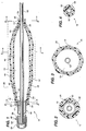
- FIG. 1 of the drawings is an axial longitudinal sectional view of a variable distention angioplasty balloon assembly in a partially dilated condition, with a catheter aligned and enclosed therein.
- FIG. 2 of the drawings is a diametrical sectional view through the assembly in FIG. 1 and is taken along line 2-2 of FIG. 1.
- FIG. 3 of the drawings is a diametrical sectional view through the assembly in FIG. 1 and is taken along line 3-3 of FIG. 1.
- FIG. 4 of the drawings is a diametrical sectional view through the assembly in FIG. 1 and is taken along line 4-4 of FIG. 1.
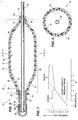
- FIG. 5 of the drawings is an axial longitudinal sectional view, similar to the view in FIG. 1, illustrating the balloon assembly thereof in a fully expanded condition, with a catheter aligned therein.
- FIG. 6 of the drawings is a diametrical sectional view of FIG. 5 and is taken along the line 6-6 in FIG. 5.
- FIG. 7 of the drawings is a graph illustrating the predicted pressure and diameter characteristic curve of the balloon assembly in FIG. 1.
- FIG. 1 illustrated in FIG. 1 is a variable distention angioplasty balloon assembly 10, for insertion into and dilation of an anatomical stricture in a blood vessel or other body cavity.
- the multi-layer balloon assembly 10 includes an inner elongated, inflatable balloon 12 having a distal portion 14, a proximal portion 16 and an intermediate portion 18 therebetween and defining therein a first chamber 19.
- the inner balloon 12 has a pre-selected first modulus of elasticity (Young's modulus of elasticity) thereby having a predicted fixed-linear pressure-diameter characteristic or relationship as illustrated in Region A in FIG. 7.
- the assembly 10 further includes an outer elongated, inflatable balloon 20 having a distal portion 22, a proximal portion 24 and an intermediate portion 26 therebetween positioned around the first balloon 12 and defining a second chamber 27 between the balloons.
- the outer balloon 20 has a second modulus of elasticity (Young's modulus of elasticity) different from the inner balloon 12.
- the outer balloon 20 second modulus of elasticity has a predicted fixed-linear pressure-diameter characteristic or relationship as illustrated in Region B in FIG. 7.
- the inner balloon 12 is substantially enclosed by and longitudinally co-extensive with the outer balloon 20. As shown in FIG. 7, the predicted first modulus of elasticity of the inner balloon 12 is less than the second modulus of elasticity of the outer balloon 20.
- the balloons 12 and 20 are substantially impermeate thereby having the predicted characteristics illustrated in FIG. 7.
- the inner and outer balloons 12 and 20 distal portions 14 and 22 include port sections 15 and 23 and the proximal portions 16 and 24 include port sections 17 and 25, respectively, for allowing a catheter and further means for dilating the assembly 10.
- the distal port sections 15 and 23 are adhesively sealed or preferably heat sealed to each other, for a good seal and are attached to a catheter.
- the proximal port sections 17 and 25 are adhesively sealed or preferably heat sealed to each other for improved seals, and attached to other means, such as a hub or an intermediate section for inflating or dilating assembly 10.
- the first chamber 19 of the inner balloon 12 and the second chamber 27 of the outer balloon 20 define a variable dilation structure 28 (dashed rectangle in FIG. 1) for dilating an anatomical stricture.
- the variable dilation structure 28 with the predicted variable characteristic curve in FIG. 7 has a first linear diameter and pressure characteristic curve (solid line in Region A) defined by the modulus of elasticity of the inner balloon 12 and a second linear diameter and pressure characteristic curve (solid line in Region B) defined by the modulus of elasticity of the outer balloon 20.
- the variable characteristic curve includes a first diameter and pressure characteristic in Region A, defined by the modulus of elasticity of the inner balloon 12 and a second diameter and pressure characteristic curve in Region B, defined by the modulus of elasticity of the outer balloon 20.
- the assembly 10 allows a physician for example, to dilate an anatomical stricture with the use of the inner balloon 12 characteristic curve alone, or the combination of the characteristic with the outer balloon 20 characteristic curve for a slightly larger diameter with a smaller incremental increase in pressure, without the need of withdrawing a narrow first balloon in a mono-layer balloon assembly and reinserting a wider second balloon, with all the inherent risks associated with reinserting a second balloon.
- the inner balloon 12 is more elastic and has the first characteristics in FIG. 7, and the outer balloon 20 is less elastic and has the second characteristic curve.
- the combination of first and second characteristic curve in dilation structure 28 advantageously gives a physician increased flexibility, by allowing him or her to increase the pressure in the desired working pressure range in FIG. 7, with a smaller increase in diameter of structure 28, for more precise dilating of an anatomical stricture with minimal chances of bursting.
- mono-layer balloon assemblies which have distention properties which are not variable and which behave similar to those in first characteristic curve alone (solid and dashed line in FIG. 7) or second characteristic curve alone, along their entire range in FIG. 7.
- first characteristic curve alone solid and dashed line in FIG. 7
- second characteristic curve alone along their entire range in FIG. 7.
- the assembly 10 provides a clinician the opportunity to increase the pressure in the desired working pressure range without a significant diameter increase, while working in a safe working pressure range in FIG. 7.
- the assembly 10 provides a clinician with the ability to vary the inflated structure 28 diameter within a narrow-safe pressure range, and further allows a pressure increase with less size increase, than is provided by a conventional mono-layer balloon, resulting in improved substantially uniform radial pressure circumferentially about, along the length and diameter of the dilation structure 28 in proximity to the stricture being dilated. Further, the assembly 10 provides the benefit of eliminating the need to change to a second catheter with a larger balloon diameter when a larger dilating diameter is required in mono-layer assemblies, for example.
- a further advantage of assembly 10, is that the structure 28 includes the outer balloon 20 enclosing the inner balloon 12, thereby minimizing the possibility of rupture of structure 28. If the inner balloon 12 should rupture, as can happen during inflation, the assembly 10 has a reduced potential for vessel damage and minimal chances of loosing a piece of the ruptured balloon in the bloodstream, because such pieces will be collected in the outer balloon 20.
- the outer balloon 20 and the inner balloon 12 reinforce the variable dilation structure 28 so as to minimize the possibility of rupture of balloons 12 and 20 individually, and also provides a more durable and resilient structure 28 which can withstand greater inflation pressures, and provide an improved degree of protection when expanded, inserted or removed, or when deploying a stent, which many times in a single balloon assembly has a tendency to puncture or burst.
- the assembly 10 can be used for many types of dilation products, such as angioplasty, valvuloplasty, urethroplasty, salpingoplasty, and the like.
- the assembly 10 can be attached to an over the wire, fixed wire, hybrid over the wire or rapid exchange monorail type dilation system.
- the assembly 10 is particularly suited for dilating blood vessels within an area of stenosis.
- the assembly 10 can also be used to deploy a stent in a body cavity or blood vessel (not shown in the drawings).
- the stent is received around the assembly 10 structure 28, and the entire dilating structure 28 and the stent is received within a body cavity.
- the elasticity of the balloons 12 and 20 exert radially outwardly pressure to and against a stent (not shown in the FIGS.), to expand the stent as desired against an appropriate body cavity.
- the dilating structure 28 is deflated and removed.
- the inner balloon 12 and the outer balloon 20 are tubular, annular, flexible and expandable and comprise a polymeric material.
- the inner and outer balloons 12 and 20 comprise at least one polymeric material selected from the group consisting of polyolefins, copolymers of polyolefins, polyamides, polyvinyl chloride, polyethylene terephthalate, and combinations and permutations thereof more preferably a polyamide such as nylon (registered trademark) because of its desirable properties, such as elasticity, durability, formability, manufacturability, etc.
- the inner and outer balloons 12 and 20 comprise a polyamide such as 70D nylon and 75D nylon (registered trademark), respectively, for desirable properties.
- the balloon assembly 10 further includes a hub 36 having a first member 38 with a port 40 and an annular and tubular intermediate section 42 for inflating the inner balloon 12 until it reaches the outer balloon 20, and thereafter both balloons 12 and 20.
- the hub 36 is attached to and circumferentially around a proximal portion of the intermediate section 42, and the intermediate section 42 at the other end is attached to and circumferentially within a portion of the proximal portions 16 and 24 of the balloons 12 and 20 defining the dilation structure 28.
- the assembly 10 further includes an inflating device for inflating balloons 12 and 20, connected to member 38 (not shown in the drawings).
- the dilating structure 28 further includes the intermediate portions 18 and 26 of the inner and outer balloons 12 and 20 forming a first inclined section 46, a middle section 48 and a second inclined section 50.
- the first inclined section 46 is axially-adjacent to the proximal portions 16 and 24 of the balloons 12 and 20, respectively
- the second inclined section 50 is axially-adjacent to the distal portions 14 and 22 of the balloons 12 and 20, respectively.
- the first and second inclined sections 46 and 50 extend outwardly at an angle ranging from about 5° to about 85° when dilated, with respect to an axial or elongate axis extending through the center of the assembly 10 in FIG. 5, and preferably ranging from about 15° to 60°, and most preferably about 45° for a smooth and gradual increase and decrease in diameter for improved durability and flexibility.
- the balloon assembly 10 includes a catheter 52 positioned and enclosed in the inner balloon 12 in alignment with the elongate axis for facilitating the insertion of the dilation structure 28 in a body cavity.
- the balloon assembly 10 further includes a path 56 (dashed line) from the hub 36 port 40 to the proximal portion 16 of the inner balloon 12 for inflating the balloons 12 and 20.
- the path 56 provides a means for delivery of dilatation fluid, such as a de-enzo fluid to structure 28.
- the path 56 also receives the catheter 52 partially therealong.
- the first modulus of elasticity of the inner balloon 12 can range widely.
- the modulus of elasticity ranges from about 2% 9,87 ⁇ 10 -6 Pa (atmosphere (atm)) to about 5% 9,87 ⁇ 10 -6 Pa (atm), and typically is about 3.5% 9,87 ⁇ 10 -6 Pa (atm).
- the second modulus of elasticity of the outer balloon 20 can range widely. Preferably, it ranges from about 0.5% 9,87 ⁇ 10 -6 Pa (atm) to about 2% 9,87 ⁇ 10 -6 Pa (atm), and typically is about 1% / atm.
- the intermediate portions 18 and 26 of the balloons 12 and 20 in FIG. 5 are substantially adjacent and have a substantially similar dilation diameter therealong, with the diameter of the inner balloon 12 being slightly smaller than that of the outer balloon 20, for providing a substantially uniform and durable circumferential and outward radial pressure to the stricture being dilated.
- the length of the dilation structure 28 can range widely depending on the intended application. In one embodiment, the length ranges from about 50 mm to about 10 mm, preferably about 30 mm to about 10 mm, and typically about 20 mm in length for angioplasty dilation products.
- the diameter of the structure 28 can range widely depending on the intended application, preferably the diameter ranges from about 30 mm to about 1 mm, and more preferably from about 1 mm to about 5 mm in diameter when used as an angioplasty dilation product.
- each balloon 12 and 20 each have wall thicknesses that can vary widely depending on the material utilized.
- each balloon 12 and 20 has a wall thickness of about 50,8 ⁇ 10 -3 mm (2 mils) or less, preferably about 25,4 ⁇ 10 -3 mm (1 mil) or less when utilizing a polymeric material.
- One preferred material is a polyamide, for elasticity, durability, strength, and minimal volume and surface area for ease of insertion and withdrawal into and out of a body cavity.
- a physician utilizing dilation structure 28 performs the following procedure. First, a physician inserts structure 28 about the stricture to be dilated, such as in an area of stenosis. Next, he or she dilates dilation structure 28 in the stricture. Initially the inner balloon 12 diameter grows or increases independently until it reaches or touches the walls of the outer balloon 20 in FIGS. 5 and 6 (see the first characteristic curve in FIG. 7). Thereafter, as the pressure is further increased, the diameter of the dilation structure 28 increases more slowly, which is dependant upon the modulus of elasticity of the outer balloon 20.
- the dilation step can include two stages, including following the solid line in Region A alone and thereafter, if needed, following the solid line in Region B.
- the dilation structure 28 diameter increases linearly and fairly rapidly as indicated in first characteristic curve.
- Region B the inner balloon 12 reaches the outer balloon 20, as shown in FIG. 6, and the diameter increases more slowly but still linearly, as indicated in the second characteristic curve (solid line).
- the balloons 12 and 20 improve resistance to rupture and provide a smooth circumferential surface and radial pressure along the middle section 48 of the dilation structure 28 about the stricture being dilated. Thereafter, the apparatus 10 is deflated and removed.
Claims (17)
- Angioplastie-Balloneinheit (10) mit variabler Aufweitung zum Einsetzen in ein Blutgefäß, mit:einem inneren in die Länge gezogenen, aufblasbaren Ballon (12), welcher ein distales Teil (14), ein proximales Teil (16) und ein dazwischen befindliches Zwischenteil (18) aufweist und darin eine erste Kammer (19) definiert, wobei der innere Ballon einen ersten Young-Modul aufweist;einem äußeren in die Länge gezogenen, aufblasbaren Ballon (20), welcher ein distales Teil (22), ein proximales Teil (24) und ein dazwischen befindliches Zwischenteil (26) aufweist, um den inneren Ballon positioniert ist und zwischen den Ballons eine zweite Kammer (27) definiert, wobei der äußere Ballon einen zweiten Young-Modul aufweist, wobei der innere Ballon im wesentlichen in dem äußeren Ballon eingeschlossen ist; undwobei die erste Kammer (19) des inneren Ballons und die zweite Kammer (27) des äußeren Ballons eine variable Dehnungsstruktur (28) zum Dehnen einer anatomischen Verengung definieren, dadurch gekennzeichnet, daßder erste Young-Elastizitätsmodul des inneren Ballons (12) kleiner als der zweite Young-Elastizitätsmodul des äußeren Ballons (20) ist, undder innere und äußere Ballon (12, 20) derart zueinander angeordnet sind und miteinander zusammenwirken, daß die Dehnungstruktur mit einer variablen Charakteristik einen ersten Durchmesser und eine Druckcharakteristikkurve, welche durch eine erste Rate einer radialen Ausdehnung in Abhängigkeit des Young-Elastizitätsmoduls des inneren Ballons (12) definiert sind, und einen zweiten Durchmesser und eine Druckcharakteristikkurve aufweist, welche durch eine zweite Rate einer radialen Ausdehnung in Abhängigkeit des kombinierten Young-Elastizitätsmoduls des inneren Ballons (12) und des äußeren Ballons (20) definiert sind.
- Einheit nach Anspruch 1, dadurch gekennzeichnet, daß der innere und äußere Ballon (12, 20) derart zueinander angeordnet sind und miteinander zusammenwirken, daß sie im wesentlichen denselben Arbeitsdurchmesser aufweisen.
- Einheit nach Anspruch 1, dadurch gekennzeichnet, daß der innere und äußere Ballon (12, 20) röhrenförmig, ringförmig, flexibel und ausdehnbar ausgebildet sind.
- Einheit nach Anspruch 1, dadurch gekennzeichnet, daß der innere und äußere Ballon (12, 20) aus einem polymeren Material besteht.
- Einheit nach Anspruch 1, dadurch gekennzeichnet, daß der innere und äußere Ballon (12, 20) wenigstens ein polymeres Material aufweisen, welches aus der Gruppe bestehend aus Polyolefinen, Copolymeren von Polyolefinen, Polyamiden, Polyvinylchlorid und Polyethylenterephthalat gewählt ist.
- Einheit nach Anspruch 1, gekennzeichnet durch einen Katheder (52), welcher in Längsrichtung in dem inneren Ballon (12) ausgerichtet ist.
- Einheit nach Anspruch 1, dadurch gekennzeichnet, daß die erste Rate der radialen Ausdehnung des inneren Ballons (12) in einem Bereich von etwa 2% pro 9,87 x 10⁻⁶ Pa (pro atm) des inneren Ballondrucks bis etwa 5% pro 9,87 x 10⁻⁶ Pa (pro atm) des inneren Ballondrucks liegt.
- Einheit nach Anspruch 1, dadurch gekennzeichnet, daß die zweite Rate der radialen Ausdehnung des inneren und äußeren Ballons (12, 20) in einem Bereich von etwa 0,5% pro 9,87 x 10⁻⁶ Pa (pro atm) des inneren Ballondrucks bis etwa 2,0% pro 9,87 x 10⁻⁶ Pa (pro atm) des inneren Ballondrucks liegt.
- Einheit nach Anspruch 1, gekennzeichnet durch einen in Form hergestellten Trichterabschnitt (36), welcher eine Öffnung (40) zum Aufblasen des Ballons und einen Zwischenabschnitt (42) aufweist, wobei der Zwischenabschnitt (42) an einem Teil der proximalen Teile (16, 24) des inneren und äußeren Ballons (12, 20) an einem Ende und an dem Trichter (36) an dem anderen Ende befestigt ist.
- Einheit nach Anspruch 1, gekennzeichnet durch einen in Form hergestellten Trichterabschnitt (36), welcher ein erstes Teil (38) aufweist, welches eine Öffnung (40) einschließlich eines dazwischen befindlichen röhrenförmigen Abschnitts (42) besitzt, welcher sich bezüglich seines Umfangs innerhalb der proximalen Teile (16, 24) des inneren und äußeren Ballons (12, 20) erstreckt und daran befestigt ist.
- Einheit nach Anspruch 1, dadurch gekennzeichnet, daß die variable Dehnungsstruktur die Zwischenteile (18, 26) des inneren und äußeren Ballons (12, 20) aufweist, welche im wesentlichen dort entlang während der Dehnung davon benachbart sind.
- Einheit nach Anspruch 1, dadurch gekennzeichnet, daß die variable Dehnungsstruktur eine Länge bezüglich der Zwischenteile (18, 26) des inneren und äußeren Ballons (12, 20) von etwa 50mm oder weniger und einen Durchmesser von etwa 5mm oder weniger aufweist.
- Einheit nach Anspruch 1, dadurch gekennzeichnet, daß die Dehnungstruktur einen ersten geneigten Abschnitt (46), einen mittleren Abschnitt (48) und einen zweiten geneigten Abschnitt (50) aufweist, wobei der erste geneigte Abschnitt (46) benachbart zu dem proximalen Teil (16, 24) des inneren und äußeren Ballons (12, 20) lokalisiert ist und der zweite geneigte Abschnitt (50) benachbart zu den distalen Teilen (14, 22) des inneren und äußeren Ballons (12, 20) lokalisiert ist.
- Einheit nach Anspruch 13, dadurch gekennzeichnet, daß sich der erste und zweite geneigte Abschnitt (46, 50) nach außen unter einem Winkel im Bereich von etwa 5° bis etwa 85° bezüglich einer Längsachse erstrecken, welche sich durch die Einheit erstreckt.
- Einheit nach Anspruch 1, dadurch gekennzeichnet, daß der erste Ballon (12) und der zweite Ballon (20) undurchlässig sind.
- Einheit nach Anspruch 1, gekennzeichnet durch eine Einrichtung zum Aufblasen des inneren und äußeren Ballons (12, 20).
- Einheit nach Anspruch 1, dadurch gekennzeichnet, daß der erste Ballon (12) und der zweite Ballon (20) jeweils eine im wesentlichen gleichförmige Wanddicke von etwa 50,8 x 10⁻³ mm (2 mils) oder weniger aufweisen.
Applications Claiming Priority (2)
| Application Number | Priority Date | Filing Date | Title |
|---|---|---|---|
| US07/929,671 US5342305A (en) | 1992-08-13 | 1992-08-13 | Variable distention angioplasty balloon assembly |
| US929671 | 1992-08-13 |
Publications (3)
| Publication Number | Publication Date |
|---|---|
| EP0582870A2 EP0582870A2 (de) | 1994-02-16 |
| EP0582870A3 EP0582870A3 (de) | 1994-04-13 |
| EP0582870B1 true EP0582870B1 (de) | 1997-09-24 |
Family
ID=25458261
Family Applications (1)
| Application Number | Title | Priority Date | Filing Date |
|---|---|---|---|
| EP93111706A Expired - Lifetime EP0582870B1 (de) | 1992-08-13 | 1993-07-21 | Angioplastie-Balloneinheit mit variabler Aufweitung |
Country Status (3)
| Country | Link |
|---|---|
| US (1) | US5342305A (de) |
| EP (1) | EP0582870B1 (de) |
| DE (1) | DE69314116T2 (de) |
Cited By (4)
| Publication number | Priority date | Publication date | Assignee | Title |
|---|---|---|---|---|
| US6506201B2 (en) | 1996-08-23 | 2003-01-14 | Scimed Life Systems, Inc. | Balloon catheter with stent securement means |
| US8152819B2 (en) | 1996-08-23 | 2012-04-10 | Boston Scientific Scimed, Inc. | Catheter support for stent delivery |
| WO2013080213A1 (en) * | 2011-12-02 | 2013-06-06 | Sil Vascular Ltd. | Balloon catheter system |
| US8709062B2 (en) | 1996-08-23 | 2014-04-29 | Boston Scientific Scimed, Inc. | Stent delivery system having stent securement apparatus |
Families Citing this family (121)
| Publication number | Priority date | Publication date | Assignee | Title |
|---|---|---|---|---|
| US5460610A (en) * | 1990-01-12 | 1995-10-24 | Don Michael; T. Anthony | Treatment of obstructions in body passages |
| US5308320A (en) * | 1990-12-28 | 1994-05-03 | University Of Pittsburgh Of The Commonwealth System Of Higher Education | Portable and modular cardiopulmonary bypass apparatus and associated aortic balloon catheter and associated method |
| US5447497A (en) * | 1992-08-06 | 1995-09-05 | Scimed Life Systems, Inc | Balloon catheter having nonlinear compliance curve and method of using |
| US5348538A (en) * | 1992-09-29 | 1994-09-20 | Scimed Life Systems, Inc. | Shrinking balloon catheter having nonlinear or hybrid compliance curve |
| US5500180A (en) | 1992-09-30 | 1996-03-19 | C. R. Bard, Inc. | Method of making a distensible dilatation balloon using a block copolymer |
| JP3577082B2 (ja) | 1993-10-01 | 2004-10-13 | ボストン・サイエンティフィック・コーポレーション | 熱可塑性エラストマーから成る医療装置用バルーン |
| US6896842B1 (en) | 1993-10-01 | 2005-05-24 | Boston Scientific Corporation | Medical device balloons containing thermoplastic elastomers |
| US5843116A (en) * | 1996-05-02 | 1998-12-01 | Cardiovascular Dynamics, Inc. | Focalized intraluminal balloons |
| US6027486A (en) * | 1996-05-02 | 2000-02-22 | Radiance Medical Systems, Inc. | Interactive angioplasty |
| US5520646A (en) * | 1994-03-03 | 1996-05-28 | D'andrea; Mark A. | Diagnostic marking catheter system for use in radiation diagnosis procedure |
| US6248131B1 (en) | 1994-05-06 | 2001-06-19 | Advanced Bio Surfaces, Inc. | Articulating joint repair |
| US5888220A (en) * | 1994-05-06 | 1999-03-30 | Advanced Bio Surfaces, Inc. | Articulating joint repair |
| US5522882A (en) * | 1994-10-21 | 1996-06-04 | Impra, Inc. | Method and apparatus for balloon expandable stent-graft delivery |
| US5749851A (en) | 1995-03-02 | 1998-05-12 | Scimed Life Systems, Inc. | Stent installation method using balloon catheter having stepped compliance curve |
| FR2733143B1 (fr) * | 1995-04-21 | 1997-11-07 | Nycomed Lab Sa | Dispositif d'obturation temporaire d'un canal corporel, notamment utile a l'assistance cardiaque par contre-pression |
| NL1000413C2 (nl) * | 1995-05-22 | 1996-11-25 | Cordis Europ | Balloncatheter met ballonbeschermingsmantel. |
| US5766201A (en) * | 1995-06-07 | 1998-06-16 | Boston Scientific Corporation | Expandable catheter |
| US20050131267A1 (en) * | 1995-06-07 | 2005-06-16 | Talmadge Karen D. | System and method for delivering a therapeutic agent for bone disease |
| US20050131268A1 (en) * | 1995-06-07 | 2005-06-16 | Talmadge Karen D. | System and method for delivering a therapeutic agent for bone disease |
| JP3306857B2 (ja) * | 1995-08-04 | 2002-07-24 | ニプロ株式会社 | 血管拡張カテーテル |
| US5868704A (en) * | 1995-09-18 | 1999-02-09 | W. L. Gore & Associates, Inc. | Balloon catheter device |
| US20060271091A1 (en) * | 1995-09-18 | 2006-11-30 | Campbell Carey V | Balloon catheter device |
| US6124007A (en) * | 1996-03-06 | 2000-09-26 | Scimed Life Systems Inc | Laminate catheter balloons with additive burst strength and methods for preparation of same |
| US5713949A (en) * | 1996-08-06 | 1998-02-03 | Jayaraman; Swaminathan | Microporous covered stents and method of coating |
| US5944726A (en) * | 1996-08-23 | 1999-08-31 | Scimed Life Systems, Inc. | Stent delivery system having stent securement means |
| US5980530A (en) * | 1996-08-23 | 1999-11-09 | Scimed Life Systems Inc | Stent delivery system |
| US6395008B1 (en) | 1996-08-23 | 2002-05-28 | Scimed Life Systems, Inc. | Stent delivery device using stent cups and mounting collars |
| US6391032B2 (en) | 1996-08-23 | 2002-05-21 | Scimed Life Systems, Inc. | Stent delivery system having stent securement means |
| US6007543A (en) * | 1996-08-23 | 1999-12-28 | Scimed Life Systems, Inc. | Stent delivery system with stent securement means |
| EP0835673A3 (de) | 1996-10-10 | 1998-09-23 | Schneider (Usa) Inc. | Katheter für Gewebedilatation und Arzneimittelverabreichung |
| AU7178698A (en) | 1996-11-15 | 1998-06-03 | Advanced Bio Surfaces, Inc. | Biomaterial system for in situ tissue repair |
| US5843027A (en) * | 1996-12-04 | 1998-12-01 | Cardiovascular Dynamics, Inc. | Balloon sheath |
| US5769817A (en) * | 1997-02-28 | 1998-06-23 | Schneider (Usa) Inc. | Coextruded balloon and method of making same |
| US6132397A (en) * | 1997-05-01 | 2000-10-17 | Chase Medical Inc. | Integral aortic arch infusion clamp catheter |
| US5868708A (en) * | 1997-05-07 | 1999-02-09 | Applied Medical Resources Corporation | Balloon catheter apparatus and method |
| US5980531A (en) * | 1997-09-11 | 1999-11-09 | Schneider Inc | Stent deployment device with two balloons |
| IL135360A (en) * | 1997-10-01 | 2005-07-25 | Boston Scient Ltd | Body track dilation systems and related methods |
| US5961536A (en) * | 1997-10-14 | 1999-10-05 | Scimed Life Systems, Inc. | Catheter having a variable length balloon and method of using the same |
| US6168586B1 (en) * | 1998-08-07 | 2001-01-02 | Embol-X, Inc. | Inflatable cannula and method of using same |
| DE19933279A1 (de) * | 1999-07-14 | 2001-03-01 | Biotronik Mess & Therapieg | Polymerwerkstoff |
| US7892201B1 (en) | 1999-08-27 | 2011-02-22 | Gore Enterprise Holdings, Inc. | Balloon catheter and method of mounting same |
| US6471672B1 (en) | 1999-11-10 | 2002-10-29 | Scimed Life Systems | Selective high pressure dilation balloon |
| US7052510B1 (en) * | 2000-06-14 | 2006-05-30 | Medinol, Ltd. | Two Balloon staged stent expansion |
| US6796960B2 (en) * | 2001-05-04 | 2004-09-28 | Wit Ip Corporation | Low thermal resistance elastic sleeves for medical device balloons |
| US6605056B2 (en) | 2001-07-11 | 2003-08-12 | Scimed Life Systems, Inc. | Conformable balloon |
| US6726714B2 (en) * | 2001-08-09 | 2004-04-27 | Scimed Life Systems, Inc. | Stent delivery system |
| US8328710B2 (en) * | 2002-11-06 | 2012-12-11 | Senorx, Inc. | Temporary catheter for biopsy site tissue fixation |
| US6923754B2 (en) * | 2002-11-06 | 2005-08-02 | Senorx, Inc. | Vacuum device and method for treating tissue adjacent a body cavity |
| US7744620B2 (en) * | 2003-07-18 | 2010-06-29 | Intervalve, Inc. | Valvuloplasty catheter |
| US20050209674A1 (en) * | 2003-09-05 | 2005-09-22 | Kutscher Tuvia D | Balloon assembly (V) |
| US7261730B2 (en) * | 2003-11-14 | 2007-08-28 | Lumerx, Inc. | Phototherapy device and system |
| JP2007532279A (ja) * | 2004-04-19 | 2007-11-15 | イーティービュー リミテッド | 撮像カテーテル |
| US7662082B2 (en) | 2004-11-05 | 2010-02-16 | Theragenics Corporation | Expandable brachytherapy device |
| US7727191B2 (en) * | 2005-05-13 | 2010-06-01 | Medtronic Cryocath Lp | Compliant balloon catheter |
| US8034066B2 (en) | 2005-09-15 | 2011-10-11 | Boston Scientific Scimed, Inc. | Multi-layer medical balloons |
| US7413539B2 (en) * | 2005-11-18 | 2008-08-19 | Senorx, Inc. | Treatment of a body cavity |
| US8273006B2 (en) * | 2005-11-18 | 2012-09-25 | Senorx, Inc. | Tissue irradiation |
| US8079946B2 (en) * | 2005-11-18 | 2011-12-20 | Senorx, Inc. | Asymmetrical irradiation of a body cavity |
| US7942847B2 (en) * | 2005-12-16 | 2011-05-17 | Interface Associates, Inc. | Multi-layer balloons for medical applications and methods for manufacturing the same |
| US8118844B2 (en) | 2006-04-24 | 2012-02-21 | Warsaw Orthopedic, Inc. | Expandable device for insertion between anatomical structures and a procedure utilizing same |
| US8252031B2 (en) | 2006-04-28 | 2012-08-28 | Warsaw Orthopedic, Inc. | Molding device for an expandable interspinous process implant |
| US20070270823A1 (en) | 2006-04-28 | 2007-11-22 | Sdgi Holdings, Inc. | Multi-chamber expandable interspinous process brace |
| US7785290B2 (en) * | 2006-08-07 | 2010-08-31 | Gore Enterprise Holdings, Inc. | Non-shortening high angle wrapped balloons |
| US20080097374A1 (en) * | 2006-08-07 | 2008-04-24 | Korleski Joseph E | Inflatable shaped balloons |
| US9180279B2 (en) | 2006-08-07 | 2015-11-10 | W. L. Gore & Associates, Inc. | Inflatable imbibed polymer devices |
| US20080125711A1 (en) | 2006-08-07 | 2008-05-29 | Alpini Alfred A | Catheter balloons with integrated non-distensible seals |
| US20080140173A1 (en) * | 2006-08-07 | 2008-06-12 | Sherif Eskaros | Non-shortening wrapped balloon |
| US8460240B2 (en) | 2006-08-07 | 2013-06-11 | W. L. Gore & Associates, Inc. | Inflatable toroidal-shaped balloons |
| US8287442B2 (en) * | 2007-03-12 | 2012-10-16 | Senorx, Inc. | Radiation catheter with multilayered balloon |
| US20080228023A1 (en) * | 2007-03-15 | 2008-09-18 | Senorx, Inc. | Soft body catheter with low friction lumen |
| US8740873B2 (en) * | 2007-03-15 | 2014-06-03 | Hologic, Inc. | Soft body catheter with low friction lumen |
| EP2195068B1 (de) * | 2007-09-12 | 2017-07-26 | Cook Medical Technologies LLC | Ballonkatheter zur abgabe eines therapeutischen mittels |
| US20110137245A1 (en) * | 2007-09-12 | 2011-06-09 | Cook Medical Technologies Llc | Balloon catheter with embedded rod |
| US20090143728A1 (en) * | 2007-11-30 | 2009-06-04 | Numed, Inc. | Balloon catheter with safety feature |
| EP2095795A1 (de) * | 2007-12-21 | 2009-09-02 | Abbott Laboratories Vascular Enterprises Limited | Doppellagige Ballons für medizinische Geräte |
| US8360950B2 (en) | 2008-01-24 | 2013-01-29 | Senorx, Inc. | Multilumen brachytherapy balloon catheter |
| DE102008006092A1 (de) * | 2008-01-25 | 2009-07-30 | Biotronik Vi Patent Ag | Mehrfachmembranballon und Verfahren zur Herstellung eines Mehrfachmembranballons |
| US8114136B2 (en) | 2008-03-18 | 2012-02-14 | Warsaw Orthopedic, Inc. | Implants and methods for inter-spinous process dynamic stabilization of a spinal motion segment |
| US8034022B2 (en) * | 2008-04-08 | 2011-10-11 | Cook Medical Technologies Llc | Weeping balloon catheter |
| US8206430B2 (en) * | 2008-04-21 | 2012-06-26 | Medtronic Vascular, Inc. | Endolumenal sealant delivery apparatus and methods |
| KR101464983B1 (ko) | 2008-05-01 | 2014-11-25 | 스파인셀 프러프라이어테리 리미티드 | 조직 보형물의 형성 및 삽입기구 및 그의 시스템 및 방법 |
| US20100010287A1 (en) * | 2008-07-09 | 2010-01-14 | Senorx, Inc. | Brachytherapy device with one or more toroidal balloons |
| US8056582B2 (en) * | 2008-08-08 | 2011-11-15 | Tandem Diabetes Care, Inc. | System of stepped flow rate regulation using compressible members |
| CA2739326A1 (en) * | 2008-10-10 | 2010-04-15 | Intervalve, Inc. | Valvuloplasty catheter and methods |
| DE102008060162A1 (de) * | 2008-12-02 | 2010-06-10 | Carl Zeiss Surgical Gmbh | Ballonkatheter sowie Applikator mit Ballonkatheter |
| US9579524B2 (en) | 2009-02-11 | 2017-02-28 | Hologic, Inc. | Flexible multi-lumen brachytherapy device |
| US9248311B2 (en) | 2009-02-11 | 2016-02-02 | Hologic, Inc. | System and method for modifying a flexibility of a brachythereapy catheter |
| US9250106B2 (en) | 2009-02-27 | 2016-02-02 | Tandem Diabetes Care, Inc. | Methods and devices for determination of flow reservoir volume |
| AU2010217760B2 (en) | 2009-02-27 | 2015-04-09 | Tandem Diabetes Care, Inc. | Methods and devices for determination of flow reservoir volume |
| US10207126B2 (en) | 2009-05-11 | 2019-02-19 | Cytyc Corporation | Lumen visualization and identification system for multi-lumen balloon catheter |
| DE102009053067A1 (de) * | 2009-11-13 | 2011-05-19 | Willy Rüsch GmbH | Trachealtubus mit Temperatursensor |
| US8317831B2 (en) | 2010-01-13 | 2012-11-27 | Kyphon Sarl | Interspinous process spacer diagnostic balloon catheter and methods of use |
| EP2359892B1 (de) * | 2010-02-15 | 2012-10-10 | Biotronik AG | Ballonkatheter |
| US8147526B2 (en) | 2010-02-26 | 2012-04-03 | Kyphon Sarl | Interspinous process spacer diagnostic parallel balloon catheter and methods of use |
| EP2616130A1 (de) | 2010-09-13 | 2013-07-24 | Intervalve, Inc. | Positionierbare valvuloplastie-katheter |
| US9352172B2 (en) | 2010-09-30 | 2016-05-31 | Hologic, Inc. | Using a guide member to facilitate brachytherapy device swap |
| US10342992B2 (en) | 2011-01-06 | 2019-07-09 | Hologic, Inc. | Orienting a brachytherapy applicator |
| US9839540B2 (en) | 2011-01-14 | 2017-12-12 | W. L. Gore & Associates, Inc. | Stent |
| JP5887348B2 (ja) * | 2011-07-25 | 2016-03-16 | テルモ株式会社 | 治療デバイス |
| KR20140133843A (ko) * | 2012-03-09 | 2014-11-20 | 클리어스트림 테크놀러지스 리미티드 | 정밀하게 식별가능한 부분을 갖는 의료용 풍선 |
| US9283072B2 (en) | 2012-07-25 | 2016-03-15 | W. L. Gore & Associates, Inc. | Everting transcatheter valve and methods |
| US9931193B2 (en) | 2012-11-13 | 2018-04-03 | W. L. Gore & Associates, Inc. | Elastic stent graft |
| US9101469B2 (en) | 2012-12-19 | 2015-08-11 | W. L. Gore & Associates, Inc. | Prosthetic heart valve with leaflet shelving |
| US9968443B2 (en) | 2012-12-19 | 2018-05-15 | W. L. Gore & Associates, Inc. | Vertical coaptation zone in a planar portion of prosthetic heart valve leaflet |
| US10279084B2 (en) * | 2012-12-19 | 2019-05-07 | W. L. Gore & Associates, Inc. | Medical balloon devices and methods |
| US9144492B2 (en) | 2012-12-19 | 2015-09-29 | W. L. Gore & Associates, Inc. | Truncated leaflet for prosthetic heart valves, preformed valve |
| US9192345B2 (en) | 2013-03-11 | 2015-11-24 | Mark A. D'Andrea | Radiation devices and methods |
| US10842918B2 (en) | 2013-12-05 | 2020-11-24 | W.L. Gore & Associates, Inc. | Length extensible implantable device and methods for making such devices |
| US10286190B2 (en) | 2013-12-11 | 2019-05-14 | Cook Medical Technologies Llc | Balloon catheter with dynamic vessel engaging member |
| US9486347B2 (en) | 2013-12-18 | 2016-11-08 | Timothy A. M. Chuter | Balloon catheters and systems and methods for delivering stents using such catheters |
| US9956384B2 (en) | 2014-01-24 | 2018-05-01 | Cook Medical Technologies Llc | Articulating balloon catheter and method for using the same |
| US9827094B2 (en) | 2014-09-15 | 2017-11-28 | W. L. Gore & Associates, Inc. | Prosthetic heart valve with retention elements |
| US10086213B2 (en) | 2015-04-23 | 2018-10-02 | Mark A. D'Andrea | Mobile gynecological balloon devices and methods |
| JP7248430B2 (ja) | 2016-04-21 | 2023-03-29 | ダブリュ.エル.ゴア アンド アソシエイツ,インコーポレイティド | 直径を調節可能な内部人工器官ならびに関連したシステムおよび方法 |
| US10413709B2 (en) | 2016-07-14 | 2019-09-17 | Medtronic Vascular, Inc. | High-pressure dilatation catheter balloon |
| WO2018218781A1 (zh) * | 2017-06-01 | 2018-12-06 | 刘逸 | 一种定向挤压球囊扩张导管 |
| CA3072814C (en) | 2017-09-27 | 2023-01-03 | W.L. Gore & Associates, Inc. | Prosthetic valve with expandable frame and associated systems and methods |
| WO2019089136A1 (en) | 2017-10-31 | 2019-05-09 | W. L. Gore & Associates, Inc. | Medical valve and leaflet promoting tissue ingrowth |
| US11497601B2 (en) | 2019-03-01 | 2022-11-15 | W. L. Gore & Associates, Inc. | Telescoping prosthetic valve with retention element |
| US20230190295A1 (en) * | 2019-03-08 | 2023-06-22 | William Chase | Bleeding control device |
| CN111282140B (zh) * | 2020-02-20 | 2022-02-11 | 山东省立医院 | 一种泌尿外科手术用尿道扩张器、控制系统及方法 |
Family Cites Families (14)
| Publication number | Priority date | Publication date | Assignee | Title |
|---|---|---|---|---|
| GB317604A (en) * | 1928-07-11 | 1929-08-22 | Norman Francis Pratt | Improvements in or relating to anorectal dilators |
| US3045677A (en) * | 1960-05-03 | 1962-07-24 | American Cystoscope Makers Inc | Inflatable balloon catheter |
| US4327736A (en) * | 1979-11-20 | 1982-05-04 | Kanji Inoue | Balloon catheter |
| US4608984A (en) * | 1980-10-17 | 1986-09-02 | Fogarty Thomas J | Self-retracting dilatation catheter |
| US4338942A (en) * | 1980-10-20 | 1982-07-13 | Fogarty Thomas J | Dilatation catherter apparatus |
| US4651721A (en) * | 1985-04-10 | 1987-03-24 | American Medical Systems, Inc. | Penile prosthesis system |
| US4744366A (en) * | 1986-09-10 | 1988-05-17 | Jang G David | Concentric independently inflatable/deflatable multiple diameter balloon angioplasty catheter systems and method of use |
| IN171253B (de) * | 1986-11-04 | 1992-08-22 | Bard Inc C R | |
| US4932958A (en) * | 1988-05-10 | 1990-06-12 | American Medical Systems, Inc. | Prostate balloon dilator |
| US5108415A (en) * | 1988-10-04 | 1992-04-28 | Cordis Corporation | Balloons for medical devices and fabrication thereof |
| US4983167A (en) * | 1988-11-23 | 1991-01-08 | Harvinder Sahota | Balloon catheters |
| US4994033A (en) * | 1989-05-25 | 1991-02-19 | Schneider (Usa) Inc. | Intravascular drug delivery dilatation catheter |
| WO1992011895A1 (en) * | 1990-12-28 | 1992-07-23 | Boston Scientific Corporation | Balloon drug delivery system |
| CA2309400A1 (en) * | 1991-09-12 | 1993-03-13 | Advanced Cardiovascular Systems, Inc. | Intravascular system with inflatable member and member mounted thereon |
-
1992
- 1992-08-13 US US07/929,671 patent/US5342305A/en not_active Expired - Fee Related
-
1993
- 1993-07-21 EP EP93111706A patent/EP0582870B1/de not_active Expired - Lifetime
- 1993-07-21 DE DE69314116T patent/DE69314116T2/de not_active Expired - Lifetime
Cited By (4)
| Publication number | Priority date | Publication date | Assignee | Title |
|---|---|---|---|---|
| US6506201B2 (en) | 1996-08-23 | 2003-01-14 | Scimed Life Systems, Inc. | Balloon catheter with stent securement means |
| US8152819B2 (en) | 1996-08-23 | 2012-04-10 | Boston Scientific Scimed, Inc. | Catheter support for stent delivery |
| US8709062B2 (en) | 1996-08-23 | 2014-04-29 | Boston Scientific Scimed, Inc. | Stent delivery system having stent securement apparatus |
| WO2013080213A1 (en) * | 2011-12-02 | 2013-06-06 | Sil Vascular Ltd. | Balloon catheter system |
Also Published As
| Publication number | Publication date |
|---|---|
| EP0582870A2 (de) | 1994-02-16 |
| DE69314116T2 (de) | 1998-03-19 |
| US5342305A (en) | 1994-08-30 |
| EP0582870A3 (de) | 1994-04-13 |
| DE69314116D1 (de) | 1997-10-30 |
Similar Documents
| Publication | Publication Date | Title |
|---|---|---|
| EP0582870B1 (de) | Angioplastie-Balloneinheit mit variabler Aufweitung | |
| US5304135A (en) | Axial multi-chamber angioplasty balloon assembly | |
| US5447497A (en) | Balloon catheter having nonlinear compliance curve and method of using | |
| US6471672B1 (en) | Selective high pressure dilation balloon | |
| US5318587A (en) | Pleated balloon dilatation catheter and method of use | |
| EP0669143B1 (de) | Ballondilationskatheter mit variablem Durchmesser | |
| US6544224B1 (en) | Lobed balloon catheter and method of use | |
| US9821147B2 (en) | Multilayer balloon for a catheter | |
| US7972351B2 (en) | Balloon folding design and method and apparatus for making balloons | |
| US5344402A (en) | Low profile perfusion catheter | |
| US6287314B1 (en) | Stent deploying catheter system | |
| JP3561804B2 (ja) | 膨張カテーテル | |
| EP0868926B1 (de) | Koextrudierter Ballon | |
| US6355013B1 (en) | Balloon catheter with longitudinal safety stop | |
| US5632760A (en) | Balloon catheter for stent implantation | |
| EP0414350B1 (de) | Plissierter Ballondilatationskatheter und Verfahren zur Herstellung | |
| US5843027A (en) | Balloon sheath | |
| US5846246A (en) | Dual-balloon rapid-exchange stent delivery catheter with guidewire channel | |
| US6293959B1 (en) | Balloon catheter and stent delivery system having enhanced stent retention and method | |
| US6491711B1 (en) | Balloon catheter with non-circular balloon taper and method of use | |
| GB2037166A (en) | Elongatable balloon catheter | |
| EP2919847B1 (de) | Mehrschichtiger ballon für einen katheter | |
| US7448122B1 (en) | Method of compressing a polymeric layer of an expandable medical device |
Legal Events
| Date | Code | Title | Description |
|---|---|---|---|
| PUAI | Public reference made under article 153(3) epc to a published international application that has entered the european phase |
Free format text: ORIGINAL CODE: 0009012 |
|
| AK | Designated contracting states |
Kind code of ref document: A2 Designated state(s): DE FR GB NL |
|
| PUAL | Search report despatched |
Free format text: ORIGINAL CODE: 0009013 |
|
| AK | Designated contracting states |
Kind code of ref document: A3 Designated state(s): DE FR GB NL |
|
| 17P | Request for examination filed |
Effective date: 19941007 |
|
| 17Q | First examination report despatched |
Effective date: 19950609 |
|
| GRAG | Despatch of communication of intention to grant |
Free format text: ORIGINAL CODE: EPIDOS AGRA |
|
| GRAH | Despatch of communication of intention to grant a patent |
Free format text: ORIGINAL CODE: EPIDOS IGRA |
|
| GRAH | Despatch of communication of intention to grant a patent |
Free format text: ORIGINAL CODE: EPIDOS IGRA |
|
| GRAA | (expected) grant |
Free format text: ORIGINAL CODE: 0009210 |
|
| AK | Designated contracting states |
Kind code of ref document: B1 Designated state(s): DE FR GB NL |
|
| REF | Corresponds to: |
Ref document number: 69314116 Country of ref document: DE Date of ref document: 19971030 |
|
| ET | Fr: translation filed | ||
| PLBE | No opposition filed within time limit |
Free format text: ORIGINAL CODE: 0009261 |
|
| STAA | Information on the status of an ep patent application or granted ep patent |
Free format text: STATUS: NO OPPOSITION FILED WITHIN TIME LIMIT |
|
| 26N | No opposition filed | ||
| REG | Reference to a national code |
Ref country code: GB Ref legal event code: IF02 |
|
| PGFP | Annual fee paid to national office [announced via postgrant information from national office to epo] |
Ref country code: GB Payment date: 20120718 Year of fee payment: 20 |
|
| PGFP | Annual fee paid to national office [announced via postgrant information from national office to epo] |
Ref country code: FR Payment date: 20120719 Year of fee payment: 20 Ref country code: DE Payment date: 20120718 Year of fee payment: 20 |
|
| PGFP | Annual fee paid to national office [announced via postgrant information from national office to epo] |
Ref country code: NL Payment date: 20120710 Year of fee payment: 20 |
|
| REG | Reference to a national code |
Ref country code: DE Ref legal event code: R071 Ref document number: 69314116 Country of ref document: DE |
|
| REG | Reference to a national code |
Ref country code: DE Ref legal event code: R071 Ref document number: 69314116 Country of ref document: DE |
|
| REG | Reference to a national code |
Ref country code: NL Ref legal event code: V4 Effective date: 20130721 |
|
| REG | Reference to a national code |
Ref country code: GB Ref legal event code: PE20 Expiry date: 20130720 |
|
| PG25 | Lapsed in a contracting state [announced via postgrant information from national office to epo] |
Ref country code: DE Free format text: LAPSE BECAUSE OF EXPIRATION OF PROTECTION Effective date: 20130723 |
|
| PG25 | Lapsed in a contracting state [announced via postgrant information from national office to epo] |
Ref country code: GB Free format text: LAPSE BECAUSE OF EXPIRATION OF PROTECTION Effective date: 20130720 |