EP0582675B1 - Connecteur de fibre optique symetrique - Google Patents
Connecteur de fibre optique symetrique Download PDFInfo
- Publication number
- EP0582675B1 EP0582675B1 EP92913341A EP92913341A EP0582675B1 EP 0582675 B1 EP0582675 B1 EP 0582675B1 EP 92913341 A EP92913341 A EP 92913341A EP 92913341 A EP92913341 A EP 92913341A EP 0582675 B1 EP0582675 B1 EP 0582675B1
- Authority
- EP
- European Patent Office
- Prior art keywords
- cylindrical member
- optical fiber
- latch
- receptacle
- connector
- Prior art date
- Legal status (The legal status is an assumption and is not a legal conclusion. Google has not performed a legal analysis and makes no representation as to the accuracy of the status listed.)
- Expired - Lifetime
Links
Images

Classifications
-
- G—PHYSICS
- G02—OPTICS
- G02B—OPTICAL ELEMENTS, SYSTEMS OR APPARATUS
- G02B6/00—Light guides; Structural details of arrangements comprising light guides and other optical elements, e.g. couplings
- G02B6/24—Coupling light guides
- G02B6/36—Mechanical coupling means
- G02B6/38—Mechanical coupling means having fibre to fibre mating means
- G02B6/3807—Dismountable connectors, i.e. comprising plugs
- G02B6/381—Dismountable connectors, i.e. comprising plugs of the ferrule type, e.g. fibre ends embedded in ferrules, connecting a pair of fibres
- G02B6/3826—Dismountable connectors, i.e. comprising plugs of the ferrule type, e.g. fibre ends embedded in ferrules, connecting a pair of fibres characterised by form or shape
- G02B6/3831—Dismountable connectors, i.e. comprising plugs of the ferrule type, e.g. fibre ends embedded in ferrules, connecting a pair of fibres characterised by form or shape comprising a keying element on the plug or adapter, e.g. to forbid wrong connection
-
- G—PHYSICS
- G02—OPTICS
- G02B—OPTICAL ELEMENTS, SYSTEMS OR APPARATUS
- G02B6/00—Light guides; Structural details of arrangements comprising light guides and other optical elements, e.g. couplings
- G02B6/24—Coupling light guides
- G02B6/36—Mechanical coupling means
- G02B6/38—Mechanical coupling means having fibre to fibre mating means
- G02B6/3807—Dismountable connectors, i.e. comprising plugs
- G02B6/3833—Details of mounting fibres in ferrules; Assembly methods; Manufacture
- G02B6/3834—Means for centering or aligning the light guide within the ferrule
- G02B6/3835—Means for centering or aligning the light guide within the ferrule using discs, bushings or the like
-
- G—PHYSICS
- G02—OPTICS
- G02B—OPTICAL ELEMENTS, SYSTEMS OR APPARATUS
- G02B6/00—Light guides; Structural details of arrangements comprising light guides and other optical elements, e.g. couplings
- G02B6/24—Coupling light guides
- G02B6/36—Mechanical coupling means
- G02B6/38—Mechanical coupling means having fibre to fibre mating means
- G02B6/3807—Dismountable connectors, i.e. comprising plugs
- G02B6/3833—Details of mounting fibres in ferrules; Assembly methods; Manufacture
- G02B6/3847—Details of mounting fibres in ferrules; Assembly methods; Manufacture with means preventing fibre end damage, e.g. recessed fibre surfaces
-
- G—PHYSICS
- G02—OPTICS
- G02B—OPTICAL ELEMENTS, SYSTEMS OR APPARATUS
- G02B6/00—Light guides; Structural details of arrangements comprising light guides and other optical elements, e.g. couplings
- G02B6/24—Coupling light guides
- G02B6/36—Mechanical coupling means
- G02B6/38—Mechanical coupling means having fibre to fibre mating means
- G02B6/3807—Dismountable connectors, i.e. comprising plugs
- G02B6/3873—Connectors using guide surfaces for aligning ferrule ends, e.g. tubes, sleeves, V-grooves, rods, pins, balls
- G02B6/3874—Connectors using guide surfaces for aligning ferrule ends, e.g. tubes, sleeves, V-grooves, rods, pins, balls using tubes, sleeves to align ferrules
- G02B6/3878—Connectors using guide surfaces for aligning ferrule ends, e.g. tubes, sleeves, V-grooves, rods, pins, balls using tubes, sleeves to align ferrules comprising a plurality of ferrules, branching and break-out means
-
- G—PHYSICS
- G02—OPTICS
- G02B—OPTICAL ELEMENTS, SYSTEMS OR APPARATUS
- G02B6/00—Light guides; Structural details of arrangements comprising light guides and other optical elements, e.g. couplings
- G02B6/24—Coupling light guides
- G02B6/36—Mechanical coupling means
- G02B6/38—Mechanical coupling means having fibre to fibre mating means
- G02B6/3807—Dismountable connectors, i.e. comprising plugs
- G02B6/3887—Anchoring optical cables to connector housings, e.g. strain relief features
- G02B6/3888—Protection from over-extension or over-compression
-
- G—PHYSICS
- G02—OPTICS
- G02B—OPTICAL ELEMENTS, SYSTEMS OR APPARATUS
- G02B6/00—Light guides; Structural details of arrangements comprising light guides and other optical elements, e.g. couplings
- G02B6/24—Coupling light guides
- G02B6/36—Mechanical coupling means
- G02B6/38—Mechanical coupling means having fibre to fibre mating means
- G02B6/3807—Dismountable connectors, i.e. comprising plugs
- G02B6/389—Dismountable connectors, i.e. comprising plugs characterised by the method of fastening connecting plugs and sockets, e.g. screw- or nut-lock, snap-in, bayonet type
-
- G—PHYSICS
- G02—OPTICS
- G02B—OPTICAL ELEMENTS, SYSTEMS OR APPARATUS
- G02B6/00—Light guides; Structural details of arrangements comprising light guides and other optical elements, e.g. couplings
- G02B6/24—Coupling light guides
- G02B6/36—Mechanical coupling means
- G02B6/38—Mechanical coupling means having fibre to fibre mating means
- G02B6/3807—Dismountable connectors, i.e. comprising plugs
- G02B6/3833—Details of mounting fibres in ferrules; Assembly methods; Manufacture
- G02B6/3854—Ferrules characterised by materials
-
- G—PHYSICS
- G02—OPTICS
- G02B—OPTICAL ELEMENTS, SYSTEMS OR APPARATUS
- G02B6/00—Light guides; Structural details of arrangements comprising light guides and other optical elements, e.g. couplings
- G02B6/24—Coupling light guides
- G02B6/36—Mechanical coupling means
- G02B6/38—Mechanical coupling means having fibre to fibre mating means
- G02B6/3807—Dismountable connectors, i.e. comprising plugs
- G02B6/3873—Connectors using guide surfaces for aligning ferrule ends, e.g. tubes, sleeves, V-grooves, rods, pins, balls
- G02B6/3874—Connectors using guide surfaces for aligning ferrule ends, e.g. tubes, sleeves, V-grooves, rods, pins, balls using tubes, sleeves to align ferrules
- G02B6/3878—Connectors using guide surfaces for aligning ferrule ends, e.g. tubes, sleeves, V-grooves, rods, pins, balls using tubes, sleeves to align ferrules comprising a plurality of ferrules, branching and break-out means
- G02B6/3879—Linking of individual connector plugs to an overconnector, e.g. using clamps, clips, common housings comprising several individual connector plugs
Definitions
- the present invention generally relates to devices for connecting optical waveguides, and more particularly to a push-pull, quick-release optical fiber connector which is compatible with ST-type connector receptacles.
- connector means an article which allows connection, disconnection and reconnection of two optical fibers, as opposed to a "splice,” which normally connotes a permanent connection between the fibers.
- this type of fastener includes a coupling having one or more outwardly extending projections or lugs, and a rotatable, female socket having a spiral slot therein for receiving the lugs.
- the coupling may include an integral mounting plate for affixing the connector to a connection module, as shown in U.S. Patent No. 3,947,182, or the coupling may comprise a double-ended receptacle which mates with two female sockets (one on each end of the fiber) as depicted in U.S. Patent No. 3,948,582.
- a further improvement relates to the manner in which the female socket is rotated about the coupling. It was found that such rotation could result in undesirable grinding of the fiber end faces during the connection operation.
- the connector body (ferrule) may be provided with means for aligning the ferrule with the connector receptacle, as suggested in U.S. Patent Nos. 4,272,154, 4,354,731, and 4,793,683.
- ST connector is identified as an "ST" connector ("ST” is a trademark of American Telephone and Telephone Co.), and an exemplary embodiment thereof is shown in Figure 1.
- ST connector generally comprises a double-ended receptacle 1 which accommodates two plugs 2 (only one of which is depicted in Figure 1) attached to the fiber ends.
- Each tubular end of receptacle 1 has a guide slot 3 which receives a guide stud 4 attached to the ferrule support of plug 2 ; these elements prevent rotation of the ferrule with respect to the receptacle, which could otherwise damage the fiber end faces.
- Receptacle 1 also has diametrically opposed lugs 6 which slide into spiral or J-shaped slots 7 on the bayonet cap 8 of plug 2 .
- Cap 8 is coupled to ferrule 5 in such a manner that cap 8 is free to rotate with respect to ferrule 5 .
- An alignment sleeve (not shown) for the ferrules is also typically provided within receptacle 1 . Additional features have been added to this basic ST design, such as the boot/cap extender shown in U.S. Patent No. 4,812,009, and the provision of a mechanism to allow for limited axial movement of the ferrule and the sleeve as in document EP-A-390275.
- the ST connector is fairly simple to use, it still has several disadvantages.
- the first relates to the requirement that the cap 8 be manually rotated to effect the connection to receptacle 1 . This precludes use of an ST connector in high density environments where there is insufficient room to manipulate cap 8 .
- the requirement of relative rotation between cap 8 and receptacle 1 also prevents ganging of connectors, i.e., the incorporation of multiple connectors into a single housing, such as the duplex fiber optic connectors illustrated in U.S. Patent Nos. 4,762,388, 4,611,887, and 4,687,291, which are being installed in greater numbers for use in fiber distributed data integration (FDDI).
- FDDI fiber distributed data integration
- duplex connectors typically utilize latching mechanisms to engage the connector receptacles and plugs.
- Latch arms are also used to achieve a snap-lock in several simplex connector designs, including those disclosed in U.S. Patent Nos. 4,225,214 and 4,240,695.
- One interesting latch design overcomes this problem in a quick-release, push-pull type fiber optic connector. An example of such a connector is shown in U.S. Patent No. 4,268,115.
- a slidable housing surrounds the connector plug body, the body having attached thereto and integral therewith two latches which engage an annular groove in the connector receptacle.
- SC push-pull fiber optic connector
- NTT Nippon Telegraph and Telephone Co.
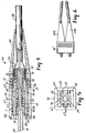
- Figure 2 An exemplary embodiment of this connector is shown in Figure 2.
- Japanese Industrial Standard JIS C 5973 for F04-type optical fiber connectors published by the Japanese Standards Association.
- This design also utilizes a double-ended receptacle 10 , but both the receptacle and the plug 11 have a rectangular cross-section.
- Plug 11 includes a ferrule holder 12 which holds the ferrule 13 .
- Ferrule holder 12 has notches 14 therein which engage with hooks 15 of latches 16 which are part of receptacle 10 .
- Plug 11 further includes a slidable housing 17 surrounding ferrule holder 12 .
- Housing 17 has slots 18 formed therein, which have side ramps 19 at their forward end.
- hooks 15 engage notches 14 .
- Pulling on the fiber optic cable will not disengage the elements, since the cable is directly attached to a backbone which is coupled only to ferrule holder 12 ; however, if housing 17 is pulled away from receptacle 10 , ramps 19 come into contact with the forward side extensions of latches 16 , raising the latches and disengaging hooks 15 from notches 14 .
- An optical fiber connector for connecting and disconnecting an optical fiber to a receptacle having a tubular end, the outer surface of the tubular end having one or more outwardly projecting lugs
- the connector comprising: a hollow, generally cylindrical member having front and rear ends; ferrule means for terminating the optical fiber, said ferrule means being located within said cylindrical member proximate said front end; at least one latch for engaging one of the lugs on the receptacle, said latch being attached to said cylindrical member proximate said front end thereof, and having an aperture therein for receiving the lug; and housing means slidably attached to said cylindrical member, said housing means having at least one ramp for disengaging said latch from the lug as said housing means is moved toward said rear end of said cylindrical member, said ramp being located front of said latch when the connector is fully engaged with the receptacle such that said rearward motion of said housing forcibly urges said ramp against said latch causing said latch to move radially outward, said ramp further being laterally shifted with respect
- the housing may have slots or cavities therein allowing the latching means to flex away from the center of the connector.
- a ferrule may be directly attached to the backbone, but it is more preferable to attach the ferrule to a ferrule holder which is coupled to the backbone in such a manner as to allow slight relative movement between the backbone and the ferrule holder.
- the backbone advantageously includes a keying stud to align the connector with the ST receptacle, and a keying guide to align the backbone with the ferrule holder.
- a boot may also be attached to the housing to provide additional strain relief and to facilitate the sliding of the housing.
- Optical fiber connector 20 is generally comprised of an exterior housing 22 which is slidably mounted over a hollow, cylindrical member or backbone 24 .
- housing 22 has a generally rectangular or square cross-section, while backbone 24 has a circular cross-section (as shown in Figure 5).
- the strength member 26 of a fiber optic cable 28 usually a Kevlar wrap ("Kevlar” is a trademark of E.I. DuPont deNemours & Co.), is exposed and secured to the proximate end of backbone 24 by means of a metallic clamp 30 .
- the outer surface of the proximate end of backbone 24 may be provided with a series of knurls or ridges 32 to enhance the gripping action of clamp 30 .
- the optical fiber 34 including its cladding and buffer 36 , passes through backbone 24 , into a passageway in ferrule holder 38 , and terminates within a ferrule 40 fixedly attached to ferrule holder 38 .
- ferrule 40 could be directly attached to backbone 24 , it is desirable to allow some relative movement between ferrule 40 and backbone 24 , as explained further below.
- Housing 22 , backbone 24 and ferrule holder 38 may be constructed of any durable material. Although polymeric materials are preferred, metallic materials may also be used, or combinations thereof. Suitable materials for housing 22 , backbone 24 and ferrule holder 38 include liquid crystal polymers, polyether sulfone (PES), polycarbonate (commercially known as LEXAN), polybutylene terephtalate (PBT), polyphenylene sulfide (PPS), polyether ether ketone (PEEK), and polyether imide (PEI).
- Ferrule 40 may be constructed from a wide variety of materials, such as metals and polymers, and particularly ceramics; zirconia is preferred.
- housing 22 may be provided with ridges/grooves 42 to assist gripping of the housing.
- a boot 44 (preferably constructed of a thermoplastic elastomer such as polyurethane) may be attached to housing 22 by means of interlocking flanges 46 and 48 . Boot 44 provides additional strain relief and facilitates manual sliding of housing 22 .
- the primary novelty in the present invention relates to the manner in which connector 20 is attached to, and detaches from, an ST-type receptacle such as the receptacle 1 shown in Figure 1. This is accomplished by providing two diametrically opposed latch arms 50 which are attached (in a hinge-like manner) to, aligned with, and preferably integral with, backbone 24 . Each latch 50 has an aperture 52 therein for receiving the lugs 6 on the tubular ends of ST receptacle 1 .
- a beveled surface is provided at the leading edge 54 of each latch arm 50 whereby, as connector 20 is inserted into receptacle 1 , lugs 6 contact beveled edges 54 , flexing latch arms 50 away from backbone 24 and allowing lugs 6 to slide under latch arms 50 until they are positioned under apertures 52 , at which time latch arms 50 snap back to their original, relaxed position.
- latch arms 50 should be constructed of a flexible and slightly elastic material, such as the previously mentioned PES, PBT or polycarbonate. Flexing may occur along the length of latch arms 50 , or just at the hinge between latch arms 50 and backbone 24 .
- any pulling force exerted on cable 28 will be transferred directly to the latch arm/lug interface by virtue of strength member 26 being attached to backbone 24 which is integral with latch arms 50 .
- connector 20 cannot be disconnected by pulling on cable 28 (or by pushing any components).
- Connector 20 may, however, be disengaged from ST receptacle 1 by simply pulling on housing 22 (or boot 44 ).
- Housing 22 has ramp surfaces 56 at its distal end, adjacent wings 57 (shown in Figure 3 but only slightly visible in Figure 5) which extend sideways from the leading edges 54 of latch arms 50 .
- housing 22 When pulled away from receptacle 1 , housing 22 slides over backbone 24 , and ramp surfaces 56 push against wings 57 , raising latch arms 50 and disengaging receptacle lugs 6 from apertures 52 . Continued pulling on housing 22 results in removal of connector 20 as housing 22 makes forcible contact with latch arms 50 at surfaces 58 . It will be noted that space must be provided adjacent latch arms 50 to allow the arms to flex away from backbone 24 . Housing 22 is thus provided with slots 60 to accommodate arms 50 as they flex. Of course, the walls of housing 22 could be thicker in which case a cavity or groove (rather than slots extending the full thickness of the walls) would suffice to allow space for latch arms 50 .
- Side pull resistance is also provided by attaching two generally parallel legs 61 (Fig. 4) to the outer surface of backbone 24 , reducing the effect of lateral forces which are applied to cable 28 .
- Side pull resistance is enhanced by the manner in which legs 61 bear against the exterior of receptacle 1 in cooperation with backbone 24 bearing against the interior of receptacle 1 .
- Legs 61 have arcuate surfaces 63 which conform to the outer shape and dimensions of the tubular end of receptacle 1 .
- Legs 61 also provide alignment between backbone 24 and housing 22 .
- ferrule 40 and backbone 24 it is also desirable to allow some relative movement between ferrule 40 and backbone 24 , in order to prevent the direct application of tension or lateral forces on fiber 34 .
- this is accomplished by allowing ferrule holder 38 to slide within backbone 24 , and by further providing a helical spring 62 which biases ferrule holder 38 in a forward, extended direction. At one end, spring 62 abuts an enlarged portion 64 of ferrule holder 38 , while the other end abuts an inwardly extending flange or annular shoulder 66 of backbone 24 .
- any pulling forces exerted on cable 28 are not felt by ferrule holder 38 (or ferrule 40 ) since they are transferred to backbone 24 via Kevlar wrap 26 and clamp 30 , and the end faces of the ferrules within the receptacle remain in forcible contact due to the biasing spring in each connector.
- Bushing 70 serves as an alignment guide to insure that the buffered fiber 36 properly enters proximate end 68 of ferrule holder 38 , and it also imparts structural integrity to the walls of backbone 24 at its clamping end.
- Bushing 70 preferably has an annular ridge 72 which fits in a corresponding groove in the inside wall of backbone 24 .
- Bushing 70 also has a passageway of sufficient diameter to allow some bowing of buffered fiber 36 therein, due to the minor axial translation of ferrule 40 which occurs when two such ferrules forcibly abut each other within receptacle 1 .
- Ferrule holder 38 is prevented from moving to far into backbone 24 by a stop 71 which abuts the end of backbone 24 .
- the length and position of ferrule 40 is such that ferrule 40 extends about 0.5 mm beyond the intended plane of contact within receptacle 1 .
- This tolerance along with an appropriately chosen spring constant for spring 62 , provides a force of about 9 newtons at the ferrule-to-ferrule interface as required by ST design specifications.
- a plurality of inwardly projecting fingers 74 are integrally formed with housing 22 to help guide one of the cylindrical ends of receptacle 1 into connector 20 .
- the ends of guide fingers 74 are curved to conform to the circular cross-section of receptacle 1 .
- Ramp surfaces 56 of housing 22 are hidden behind fingers 74 in Figure 5.
- an outwardly extending guide stud 76 is integrally formed on the surface of backbone 24 to mate with the guide slot 3 on the ST receptacle.
- the outer visible surface of housing 22 may bear a mark or raised boss 78 to apprise the user of the proper orientation of connector 20 , with respect to guide stud 76 .
- Backbone 24 is provided with another guide slot 80 which mates with a spline 82 formed on the outer surface of ferrule holder 38 .
- This keying along with that provided by guide stud 76 and guide slot 3 , insures that ferrule 40 will not rotate with respect to receptacle 1 , preventing abrasive damage that might otherwise occur when two fiber end faces abut each other within receptacle 1 , and also prevents inadvertent twisting of ferrule 40 when not engaged.
- FIG. 6 illustrates how the present invention may be incorporated into a duplex connector.
- a single housing 22' fits over the backbones of two connector subassemblies 20a and 20b . Sliding motion of housing 22' causes the internal latch arms (not shown) in subassemblies 20a and 20b to disengage from the receptacle lugs.
- housing 22' could comprise a clamshell-type assembly which would simply fit over two complete connectors 20 each having slidable housings 22 . Ridges 42 formed on the outer surface of housing 22 may be used to help secure such a clamshell assembly.
- connector 20 should have the following approximate dimensions.
- the outer diameter of that portion of backbone 24 which is surrounded by the ST receptacle is about 5.3 mm.
- the inner diameter of backbone 24 is about 3.6 mm.
- Bushing 70 is correspondingly about 3.4 mm in diameter, although it is slightly tapered for a force-fit within backbone 24 , and is about 11.0 mm in length.
- Latch arms 50 have a length of about 13.0 mm and a width of about 2.7 mm. The width of latch arms 50 across wings 57 which engage ramp surfaces 56 is about 4.8 mm.
- the diameter of apertures 52 in latch arms 50 is about 1.8 mm.
- the exterior dimensions of housing 22 are not relevant to ST compatibility, but housing 22 should be as small as practicable to allow high density interconnections; housing 22 is preferably about 10.9 mm square.
- Boot 44 is preferably about 2.8 cm long.
Abstract
Claims (6)
- Connecteur de fibre optique (20) pour connecter à et déconnecter d'une douille présentant une extrémité tubulaire une fibre optique, la surface externe de l'extrémité tubulaire présentant une ou plusieurs ergots qui font saillie vers l'extérieur, le connecteur comprenant :un élément creux (24) généralement cylindrique et présentant des extrémités frontales et postérieures,des moyens d'embout (40) pour terminer la fibre optique, les moyens d'embout (40) étant situés dans l'élément cylindrique (24) à proximité de l'extrémité frontale,au moins un moyen de blocage (50) pour entrer en prise avec un des ergots de la douille, le moyen de blocage (50) étant fixé à l'élément cylindrique (24) à proximité de son extrémité frontale et présentant une ouverture (52) pour recevoir l'ergot, etdes moyens de boîtier (22) fixés de façon coulissante à l'élément cylindrique (24), les moyens de boîtier présentant au moins une pente (56) pour mettre hors de prise ledit moyen de blocage (50) et l'ergot à mesure que les moyens de boîtier (22) sont déplacés vers l'extrémité postérieure précitée de l'élément cylindrique (24), la pente (56) étant située à l'avant du moyen de blocage (50) lorsque le connecteur (20) est complètement en prise avec la douille de façon à ce que le mouvement vers l'arrière dudit boîtier presse énergiquement la pente (56) contre le moyen de blocage (50) en amenant le moyen de blocage à se déplacer radialement vers l'extérieur, la pente (56) étant de plus décalée latéralement par rapport à ladite ouverture (52) du moyen de blocage (50) pour permettre que le moyen de blocage entre en prise ou soit mis hors de prise d'avec l'ergot sans interférence de ladite pente (56).
- Connecteur de fibre optique suivant la revendication 1, caractérisé en ce qu'il y a deux moyens de blocage (50) comprenant deux bras de blocage (50) flexibles adaptés pour entrer en prise avec deux ergots qui sont diamétralement opposés sur la surface externe de la douille, les bras de blocage (50) étant généralement parallèles et alignés avec l'élément cylindrique, s'étendant longitudinalement vers l'extrémité frontale de l'élément cylindrique (24) précité, chacun des bras de blocage présentant une ouverture (52) pour y recevoir un des ergots.
- Connecteur de fibre optique suivant la revendication 1 ou 2, caractérisé en ce que :l'élément cylindrique (24) précité comprend des moyens de tige (74) pour aligner l'élément cylindrique et une entaille de guidage de la douille, etles moyens d'embout comprennent des moyens de languettes (82) pour aligner les moyens d'embout et une entaille de guidage (80) de l'élément cylindrique.
- Connecteur de fibre optique suivant la revendication 1 ou 2 ou 3, caractérisé en ce qu'il comprend en outre des moyens pour permettre un mouvement relatif entre les moyens d'embout (40) et l'élément cylindrique (24).
- Connecteur de fibre optique suivant la revendication 1 ou 2 ou 3 ou 4, caractérisé en ce que les moyens de boîtier coulissant (22) entourent l'élément cylindrique (24) et comportent une ou plusieurs entailles (60) pour recevoir lesdits moyens de blocage (50) et comprennent en outre des éléments (61) fixés à l'élément cylindrique (24) en vue d'aligner l'élément cylindrique (24) à l'intérieur des moyens de boîtier (22) et pour fournir une résistance contre des forces latérales agissant sur la fibre optique.
- Connecteur de fibre optique suivant l'une quelconque des revendications précédentes, caractérisé en ce qu'il comprend de plus des moyens de buselure (70) situés dans l'élément cylindrique (24) à proximité de l'extrémité postérieure de celui-ci en vue d'un alignement de la fibre optique et des moyens d'embout (40).
Applications Claiming Priority (3)
| Application Number | Priority Date | Filing Date | Title |
|---|---|---|---|
| US07/692,946 US5101463A (en) | 1991-05-03 | 1991-05-03 | Push-pull optical fiber connector |
| US692946 | 1991-05-03 | ||
| PCT/US1992/002309 WO1992019999A1 (fr) | 1991-05-03 | 1992-03-23 | Connecteur de fibre optique symetrique |
Publications (2)
| Publication Number | Publication Date |
|---|---|
| EP0582675A1 EP0582675A1 (fr) | 1994-02-16 |
| EP0582675B1 true EP0582675B1 (fr) | 1997-12-03 |
Family
ID=24782701
Family Applications (1)
| Application Number | Title | Priority Date | Filing Date |
|---|---|---|---|
| EP92913341A Expired - Lifetime EP0582675B1 (fr) | 1991-05-03 | 1992-03-23 | Connecteur de fibre optique symetrique |
Country Status (20)
| Country | Link |
|---|---|
| US (1) | US5101463A (fr) |
| EP (1) | EP0582675B1 (fr) |
| JP (1) | JPH06507506A (fr) |
| KR (1) | KR100283455B1 (fr) |
| CN (1) | CN1030624C (fr) |
| AR (1) | AR244003A1 (fr) |
| AU (1) | AU659193B2 (fr) |
| BR (1) | BR9205955A (fr) |
| CA (1) | CA2108261A1 (fr) |
| CZ (1) | CZ227393A3 (fr) |
| DE (1) | DE69223404T2 (fr) |
| DK (1) | DK0582675T3 (fr) |
| ES (1) | ES2110503T3 (fr) |
| HU (1) | HU214233B (fr) |
| MX (1) | MX9201992A (fr) |
| MY (1) | MY108415A (fr) |
| PL (1) | PL168092B1 (fr) |
| RU (1) | RU2126545C1 (fr) |
| TR (1) | TR26186A (fr) |
| WO (1) | WO1992019999A1 (fr) |
Cited By (1)
| Publication number | Priority date | Publication date | Assignee | Title |
|---|---|---|---|---|
| WO2000046623A1 (fr) * | 1999-02-02 | 2000-08-10 | Infineon Technologies Ag | Manchon de couplage comportant une plaque de protection |
Families Citing this family (100)
| Publication number | Priority date | Publication date | Assignee | Title |
|---|---|---|---|---|
| US5337385A (en) * | 1991-03-01 | 1994-08-09 | The Whitaker Corporation | Optical waveguide terminating device |
| US5230032A (en) * | 1991-05-09 | 1993-07-20 | Itt Corporation | Abutting tips fiber optic connector and method of making same |
| US5166996A (en) * | 1991-05-28 | 1992-11-24 | Mccoy Bruce M | Method of, and apparatus for, protecting and curing fiber optic cable terminations |
| US5212752A (en) * | 1992-05-27 | 1993-05-18 | At&T Bell Laboratories | Optical fiber ferrule connector having enhanced provisions for tuning |
| US5263105A (en) * | 1992-05-29 | 1993-11-16 | E. I. Du Pont De Nemours And Company | Connector assembly for connecting an optical fiber cable to a socket |
| US5276752A (en) * | 1992-07-29 | 1994-01-04 | Molex Incorporated | Fiber optic connector system |
| US5245683A (en) * | 1992-08-21 | 1993-09-14 | Molex Incorporated | Board mounted fiber optic connector |
| FR2696840B1 (fr) * | 1992-10-09 | 1994-11-18 | Souriau & Cie | Fiche encliquetable de connexion de fibre optique, notamment fiche monobloc surmoulée. |
| CH685267A5 (de) * | 1992-11-26 | 1995-05-15 | Diamond Sa | Steckverbindung für Lichtwellenleiter. |
| DE9320829U1 (de) * | 1992-11-26 | 1995-03-02 | Diamond Sa | Steckverbindung für Lichtwellenleiter |
| US5317664A (en) * | 1992-12-15 | 1994-05-31 | Thomas & Betts Corporation | Fiber optic assembly and crimp sleeve used with the assembly |
| US5321784A (en) * | 1993-02-18 | 1994-06-14 | Minnesota Mining And Manufacturing Company | Pull-proof, modular fiber optic connector system |
| GB9308139D0 (en) * | 1993-04-20 | 1993-06-02 | Lemo U K Ltd | Optical fibre connector |
| US5396572A (en) * | 1993-08-10 | 1995-03-07 | At&T Corp. | Optical fiber connector having a unipartite cap |
| DE4330941C1 (de) * | 1993-09-08 | 1995-03-02 | Siemens Ag | Steckverbinder |
| US5381498A (en) * | 1993-09-16 | 1995-01-10 | Minnesota Mining And Manufacturing Company | Modular multifiber connector with phone-like plug and socket |
| US5428703A (en) * | 1994-02-18 | 1995-06-27 | Augat Inc. | One-piece SC fiber optic connector |
| US5670590A (en) * | 1994-05-06 | 1997-09-23 | Minnesota Mining And Manufacturing Company | Energy polymerizable compositions, homopolymers and copolymers of oxazolines |
| US5631986A (en) * | 1994-04-29 | 1997-05-20 | Minnesota Mining And Manufacturing Co. | Optical fiber ferrule |
| US5621834A (en) | 1994-12-22 | 1997-04-15 | Lucent Technologies Inc. | Closed alignment sleeve for optical connectors |
| US5546281A (en) | 1995-01-13 | 1996-08-13 | Methode Electronics, Inc. | Removable optoelectronic transceiver module with potting box |
| US5717533A (en) | 1995-01-13 | 1998-02-10 | Methode Electronics Inc. | Removable optoelectronic module |
| US6220878B1 (en) | 1995-10-04 | 2001-04-24 | Methode Electronics, Inc. | Optoelectronic module with grounding means |
| US5720907A (en) * | 1995-04-24 | 1998-02-24 | Lucent Technologies Inc. | Method for manufacturing an optical connector assembly |
| US5679025A (en) * | 1995-09-11 | 1997-10-21 | Amphenol Corporation | Front removable insert |
| US5781681A (en) * | 1995-11-22 | 1998-07-14 | The Whitaker Corporation | Bend limiting strain relief boot |
| US5661843A (en) * | 1996-01-30 | 1997-08-26 | Rifocs Corporation | Fiber optic probe |
| AUPN980896A0 (en) * | 1996-05-14 | 1996-06-06 | Kingfisher International Pty. Ltd. | An optical fibre device |
| US5828806A (en) * | 1996-10-10 | 1998-10-27 | Molex Incorporated | Fiber optic connector |
| JP3225202B2 (ja) * | 1997-01-24 | 2001-11-05 | ヒロセ電機株式会社 | 光コネクタ |
| JPH10300983A (ja) * | 1997-02-27 | 1998-11-13 | Seiko Instr Inc | 係止リング及び光ファイバ成端構造 |
| US6068410A (en) * | 1997-12-22 | 2000-05-30 | Siecor Corporation | Splice housing assembly and associated assembly method for mechanically decoupling a ferrule from a splice body |
| JP3934234B2 (ja) * | 1998-01-21 | 2007-06-20 | 富士通株式会社 | レセプタクルモジュール |
| US6203333B1 (en) | 1998-04-22 | 2001-03-20 | Stratos Lightwave, Inc. | High speed interface converter module |
| US6179627B1 (en) | 1998-04-22 | 2001-01-30 | Stratos Lightwave, Inc. | High speed interface converter module |
| GB9908184D0 (en) * | 1999-04-09 | 1999-06-02 | Itt Mfg Enterprises Inc | Optical fibre connector |
| US6623172B1 (en) * | 1999-05-12 | 2003-09-23 | Corning Cable Systems Llc | Removably mounted fiber optic connector and associated adapter |
| US6220873B1 (en) | 1999-08-10 | 2001-04-24 | Stratos Lightwave, Inc. | Modified contact traces for interface converter |
| US6325547B1 (en) * | 1999-10-06 | 2001-12-04 | Lucent Technologies Inc. | Optical connector having a housing assembly that is comprised of polyphenylsulfone |
| US6398423B1 (en) | 1999-12-15 | 2002-06-04 | Itt Manufacturing Enterprises, Inc. | Optic fiber retaining system |
| US6554489B2 (en) * | 2001-03-28 | 2003-04-29 | Corning Cable Systems Llc | Fiber optic cable guide and method of application |
| US6796715B2 (en) * | 2001-04-14 | 2004-09-28 | E20 Communications, Inc. | Fiber optic modules with pull-action de-latching mechanisms |
| US6692159B2 (en) * | 2001-04-14 | 2004-02-17 | E20 Communications, Inc. | De-latching mechanisms for fiber optic modules |
| US6893165B2 (en) * | 2002-03-01 | 2005-05-17 | Fci Americas Technology, Inc. | Optic fiber connectors and coupling sleeve |
| US6764225B2 (en) | 2002-03-01 | 2004-07-20 | Fci Americas Technology, Inc. | Optic fiber connectors |
| AUPS120702A0 (en) * | 2002-03-18 | 2002-04-18 | Kingfisher International Pty. Ltd. | An optical fibre connector system |
| US7118281B2 (en) * | 2002-08-09 | 2006-10-10 | Jds Uniphase Corporation | Retention and release mechanisms for fiber optic modules |
| CA2454438A1 (fr) * | 2003-02-07 | 2004-08-07 | Hypertronics Corporation | Connecteur |
| US6962445B2 (en) | 2003-09-08 | 2005-11-08 | Adc Telecommunications, Inc. | Ruggedized fiber optic connection |
| US7699533B2 (en) * | 2003-09-22 | 2010-04-20 | Belden Cdt (Canada) Inc. | Back-to-back receptacle |
| US7104702B2 (en) * | 2004-03-24 | 2006-09-12 | Corning Cable Systems Llc | Field installable optical fiber connector |
| WO2007053660A1 (fr) * | 2005-11-01 | 2007-05-10 | Molex Incorporated | Mecanisme de verrouillage destine a des emetteurs/recepteurs optiques |
| WO2007148315A1 (fr) * | 2006-06-21 | 2007-12-27 | Firecomms Limited | Connecteur optique |
| US20080013909A1 (en) * | 2006-07-14 | 2008-01-17 | Tenvera, Inc. | Modular Optical Fiber Network Interface |
| US20080011990A1 (en) * | 2006-07-14 | 2008-01-17 | Tenvera, Inc. | Installation of Fiber Optic Cables |
| US20080013956A1 (en) * | 2006-07-14 | 2008-01-17 | Tenvera, Inc. | Provisioning of Services Via an Optical Fiber Network |
| US20080013957A1 (en) * | 2006-07-14 | 2008-01-17 | Tenvera, Inc. | Service Aggregation Gateway |
| US20080013893A1 (en) * | 2006-07-14 | 2008-01-17 | Tenvera, Inc. | Optical Fiber Ferrule and Ferrule Receiver, and Method for Manufacturing the Same |
| US20080011514A1 (en) * | 2006-07-14 | 2008-01-17 | Tenvera, Inc. | Optical Fiber Distribution Apparatus and Method |
| US20080175545A1 (en) * | 2007-01-18 | 2008-07-24 | Tenvera, Inc. | Optical Connector Suitable for Field Assembly |
| US20080175540A1 (en) * | 2007-01-18 | 2008-07-24 | Tenvera, Inc. | Optical Connector Suitable for Field Assembly |
| US7591595B2 (en) * | 2007-01-24 | 2009-09-22 | Adc Telelcommunications, Inc. | Hardened fiber optic adapter |
| US7572065B2 (en) | 2007-01-24 | 2009-08-11 | Adc Telecommunications, Inc. | Hardened fiber optic connector |
| US7744286B2 (en) | 2007-12-11 | 2010-06-29 | Adc Telecommunications, Inc. | Hardened fiber optic connection system with multiple configurations |
| JP5324895B2 (ja) * | 2008-10-28 | 2013-10-23 | アダマンド工業株式会社 | 光コネクタプラグ |
| US20110200284A1 (en) * | 2009-06-12 | 2011-08-18 | Igor Zhovnirovsky | Fiber Optic Jack with High Interface Mismatch Tolerance |
| US8057106B1 (en) * | 2009-06-12 | 2011-11-15 | Applied Micro Circuits Corporation | Fiber optic connector microlens with focal plane aligning fiber trap |
| US20120155825A1 (en) * | 2010-12-17 | 2012-06-21 | Jamyuen Ko | Contamination prevention mechanism for light peak standard-a plug assembly |
| CN102565963B (zh) * | 2012-02-27 | 2017-04-26 | 深圳日海通讯技术股份有限公司 | 一种高密度光纤连接器及其装配方法 |
| US8899845B2 (en) * | 2012-05-15 | 2014-12-02 | Panduit Corp. | Fiber optic connector |
| RU2509752C2 (ru) * | 2012-06-19 | 2014-03-20 | Российская Федерация, От Имени Которой Выступает Министерство Промышленности И Торговли Российской Федерации | Способ изготовления керамических наконечников для волоконно-оптических соединителей |
| JP5518979B2 (ja) * | 2012-11-09 | 2014-06-11 | 株式会社フジクラ | 光コネクタレセプタクル、レセプタクルハウジング、光コネクタアダプタ、アダプタハウジング |
| US10001367B2 (en) * | 2013-05-24 | 2018-06-19 | The Boeing Company | Fiber optic position sensor and method for using |
| DE102013105908A1 (de) * | 2013-06-07 | 2014-12-11 | Reichle + De-Massari Ag | Zwischensteckverbindervorrichtung zur Verbindung mit einer Steckverbindervorrichtung und Steckverbindervorrichtung |
| EP3008502A1 (fr) * | 2013-06-13 | 2016-04-20 | CommScope, Inc. of North Carolina | Connecteur pour fibre optique multic ur |
| EP3014322B1 (fr) | 2013-06-27 | 2018-09-19 | CommScope Connectivity Belgium BVBA | Dispositif d'ancrage de câble à fibre optique à utiliser avec des connecteurs à fibre optique et ses procédés d'utilisation |
| US9977198B2 (en) * | 2013-07-16 | 2018-05-22 | 3M Innovative Properties Company | High retention force optical coupling |
| US9618704B2 (en) | 2013-07-31 | 2017-04-11 | Corning Optical Communications LLC | Fiber optic connector sub-assemblies having a front-loading locking ferrule holder and related fiber optic components, devices and methods |
| USD787448S1 (en) | 2014-08-18 | 2017-05-23 | Interlemo Holding S.A. | Electrical connector |
| TW201628277A (zh) * | 2015-01-26 | 2016-08-01 | 台達電子工業股份有限公司 | 傳輸線的接頭結構及傳輸線 |
| USD863221S1 (en) | 2015-09-04 | 2019-10-15 | Interlemo Holding Sa | Illuminable female connector |
| US10234641B2 (en) | 2016-06-14 | 2019-03-19 | Clearfield, Inc. | In-line sealed adapter tube |
| US10705300B2 (en) | 2017-07-14 | 2020-07-07 | Senko Advanced Components, Inc. | Small form factor fiber optic connector with multi-purpose boot assembly |
| US10281669B2 (en) | 2017-07-14 | 2019-05-07 | Senko Advance Components, Inc. | Ultra-small form factor optical connectors |
| US10718911B2 (en) | 2017-08-24 | 2020-07-21 | Senko Advanced Components, Inc. | Ultra-small form factor optical connectors using a push-pull boot receptacle release |
| US11822133B2 (en) | 2017-07-14 | 2023-11-21 | Senko Advanced Components, Inc. | Ultra-small form factor optical connector and adapter |
| EP3682277A4 (fr) | 2017-09-15 | 2021-06-02 | Commscope Technologies LLC | Connecteur pour fibres optiques à libération de passe-fil intégrée et ensembles associés |
| US11002923B2 (en) | 2017-11-21 | 2021-05-11 | Senko Advanced Components, Inc. | Fiber optic connector with cable boot release having a two-piece clip assembly |
| US11073664B2 (en) | 2018-08-13 | 2021-07-27 | Senko Advanced Components, Inc. | Cable boot assembly for releasing fiber optic connector from a receptacle |
| US10921530B2 (en) | 2018-09-12 | 2021-02-16 | Senko Advanced Components, Inc. | LC type connector with push/pull assembly for releasing connector from a receptacle using a cable boot |
| US10921531B2 (en) | 2018-09-12 | 2021-02-16 | Senko Advanced Components, Inc. | LC type connector with push/pull assembly for releasing connector from a receptacle using a cable boot |
| WO2020055440A1 (fr) | 2018-09-12 | 2020-03-19 | Senko Advanced Componetns, Inc. | Connecteur de type lc avec languette de poussée/traction à clipser pour libérer connecteur d'un réceptacle utilisant une gaine de câble |
| US11226464B2 (en) * | 2019-03-07 | 2022-01-18 | Commscope Technologies Llc | Telecommunications fan-out arrangement |
| US11340406B2 (en) | 2019-04-19 | 2022-05-24 | Senko Advanced Components, Inc. | Small form factor fiber optic connector with resilient latching mechanism for securing within a hook-less receptacle |
| CN114026480B (zh) | 2019-06-13 | 2023-05-26 | 扇港元器件有限公司 | 用于从插座端口释放光纤连接器的杆驱动闩锁臂和使用方法 |
| US11493695B2 (en) | 2019-06-25 | 2022-11-08 | Thomas C. Stewart | Sustained continuity non-powered optomechanical position switch utilizing self-testing multiplexed optocontrolling transceiver in a fiber-optic circuit |
| JP6792673B1 (ja) * | 2019-06-25 | 2020-11-25 | 日本航空電子工業株式会社 | プラグコネクタ |
| CN210864140U (zh) | 2019-12-17 | 2020-06-26 | 新确精密科技(深圳)有限公司 | 一种光纤盒子 |
| TWI750865B (zh) * | 2020-02-21 | 2021-12-21 | 劉美妙 | 光學連接器與光學連接器模組及其操作方法 |
| RU201970U1 (ru) * | 2020-10-12 | 2021-01-25 | Общество с ограниченной ответственностью "СУПР" | Волоконно-оптический соединитель |
Citations (1)
| Publication number | Priority date | Publication date | Assignee | Title |
|---|---|---|---|---|
| US4268115A (en) * | 1979-06-01 | 1981-05-19 | Tetra-Tech, Inc. | Quick-release fiber-optic connector |
Family Cites Families (44)
| Publication number | Priority date | Publication date | Assignee | Title |
|---|---|---|---|---|
| US3803409A (en) * | 1972-07-14 | 1974-04-09 | Us Army | Coaxial diode mount for use with fiber optic light guide |
| GB1456395A (en) * | 1973-11-16 | 1976-11-24 | Bicc Ltd | Optical fibre connector |
| US3904269A (en) * | 1974-01-28 | 1975-09-09 | Us Navy | Fiber optic cable connector |
| US3947182A (en) * | 1974-10-29 | 1976-03-30 | International Telephone & Telegraph Corporation | Fiber optic connector with axial tolerance relief |
| DE2759002C3 (de) * | 1977-12-30 | 1982-02-18 | Siemens AG, 1000 Berlin und 8000 München | Steckverbinder zur lösbaren Verbindung zweier Lichtwellenleiter-Kabel |
| US4190316A (en) * | 1978-02-02 | 1980-02-26 | The Deutsch Company | Lens connector for optical fibers |
| JPS54148544A (en) * | 1978-05-15 | 1979-11-20 | Oki Electric Ind Co Ltd | Optical fiber connector |
| US4225214A (en) * | 1978-09-18 | 1980-09-30 | Trw Inc. | Connector construction |
| US4185886A (en) * | 1978-10-26 | 1980-01-29 | International Telephone And Telegraph Corporation | Fiber optic connector |
| US4240695A (en) * | 1979-06-20 | 1980-12-23 | E. I. Du Pont De Nemours And Company | Optical fibers connector |
| US4354731A (en) * | 1979-10-02 | 1982-10-19 | E. I. Du Pont De Nemours And Company | Self-aligning optical fiber connector |
| US4327964A (en) * | 1979-12-20 | 1982-05-04 | Texas Instruments Incorporated | Snap-action fiber optic connector |
| JPS5878111A (ja) * | 1981-11-04 | 1983-05-11 | Sumitomo Electric Ind Ltd | 複芯コネクタ |
| US4673242A (en) * | 1981-12-21 | 1987-06-16 | Thomas & Betts Corporation | Movable closure for optical elements |
| US4429938A (en) * | 1982-01-06 | 1984-02-07 | Midland-Ross Corporation | Locking device for interfitting members |
| US4486072A (en) * | 1982-01-12 | 1984-12-04 | Augat Inc. | Optical connector and splicing device using double diameter resilient rods |
| US4547039A (en) * | 1982-04-16 | 1985-10-15 | Amp Incorporated | Housing mountable on printed circuit board to interconnect fiber optic connectors |
| CA1240184A (fr) * | 1982-05-24 | 1988-08-09 | Amp Inc | Connecteur pour membre de fibre optique |
| US4588256A (en) * | 1982-09-07 | 1986-05-13 | Minnesota Mining And Manufacturing Company | Optical fiber connector |
| US4798440A (en) * | 1983-01-24 | 1989-01-17 | Amp Incorporated | Fiber optic connector assembly |
| JPS59148287A (ja) * | 1983-02-14 | 1984-08-24 | 日本電気株式会社 | コネクタ |
| US4611887A (en) * | 1983-02-24 | 1986-09-16 | Amp Incorporated | Fiber optic connector assembly and wall outlet thereof |
| US4553813A (en) * | 1983-05-16 | 1985-11-19 | International Business Machines Corporation | Fiber optic connector system for integrated circuit modules |
| AU577099B2 (en) * | 1984-03-19 | 1988-09-15 | E.I. Du Pont De Nemours And Company | Receptacle, plug and optical connector |
| US4762389A (en) * | 1984-03-30 | 1988-08-09 | Nec Corporation | Optical fiber connector |
| US4687291A (en) * | 1984-06-08 | 1987-08-18 | Amp Incorporated | Duplex electro-fiber connector assembly |
| US4634214A (en) * | 1984-06-22 | 1987-01-06 | At&T Bell Laboratories | Optical fiber connector and article comprising same |
| US4690495A (en) * | 1984-11-14 | 1987-09-01 | Giannini Gabriel M | Optical fiber magnetic connector |
| US4793683A (en) * | 1986-05-08 | 1988-12-27 | American Telephone And Telegraph Company, At&T Bell Laboratories | Optical fiber connector |
| US4787706A (en) * | 1987-02-03 | 1988-11-29 | American Telephone And Telegraph Company, At&T Bell Laboratories | Duplex optical fiber connector |
| US4812009A (en) * | 1987-06-30 | 1989-03-14 | American Telephone And Telegraph Company, At&T Bell Laboratories | Optical fiber connector |
| US4852963A (en) * | 1987-06-30 | 1989-08-01 | American Telephone And Telegraph Company, At&T Bell Laboratories | Optical fiber biconic connector |
| US4840451A (en) * | 1987-12-08 | 1989-06-20 | Molex Incorporated | Shielded fiber optic connector assembly |
| US4872736A (en) * | 1988-04-19 | 1989-10-10 | American Telephone And Telegraph Company, At&T Bell Laboratories | Connector assembly having a latching mechanism |
| CA1314740C (fr) * | 1988-05-06 | 1993-03-23 | Hiroshi Okada | Bouchon pour cable de fibres optiques |
| DE58908131D1 (de) * | 1988-06-09 | 1994-09-08 | Erni Elektroapp | Zweiteiliger Steckverbinder für Lichtwellenleiter. |
| US4898446A (en) * | 1988-10-28 | 1990-02-06 | American Telephone And Telegraph Company, At&T Bell Laboratories | Optical fiber connector |
| US4936662A (en) * | 1989-02-10 | 1990-06-26 | Minnesota Mining And Manufacturing Company | Optical fiber connector |
| GB2229829B (en) * | 1989-03-31 | 1993-03-17 | Philips Nv | A connector for a fibre optic cable |
| FR2646242B1 (fr) * | 1989-04-24 | 1991-07-12 | Radiall Sa | Dispositif de connexion de fibre optique et boitier de connexion apte a recevoir un tel dispositif |
| GB2233471B (en) * | 1989-06-30 | 1993-02-24 | Philips Nv | Optical fibre connectors |
| US4961624A (en) * | 1989-08-29 | 1990-10-09 | Amp Incorporated | Optical fiber termination with crimping body |
| US4984865A (en) * | 1989-11-17 | 1991-01-15 | Minnesota Mining And Manufacturing Company | Thermoplastic adhesive mounting apparatus and method for an optical fiber connector |
| US5029973A (en) * | 1990-06-04 | 1991-07-09 | Xintec Corporation | Bayonet connector with optical, electrical or fluid uses |
-
1991
- 1991-05-03 US US07/692,946 patent/US5101463A/en not_active Expired - Fee Related
-
1992
- 1992-02-24 RU RU93058664A patent/RU2126545C1/ru active
- 1992-03-23 JP JP4511810A patent/JPH06507506A/ja active Pending
- 1992-03-23 KR KR1019930703326A patent/KR100283455B1/ko not_active IP Right Cessation
- 1992-03-23 BR BR9205955A patent/BR9205955A/pt not_active Application Discontinuation
- 1992-03-23 EP EP92913341A patent/EP0582675B1/fr not_active Expired - Lifetime
- 1992-03-23 AU AU21828/92A patent/AU659193B2/en not_active Ceased
- 1992-03-23 DK DK92913341.1T patent/DK0582675T3/da active
- 1992-03-23 HU HU9302962A patent/HU214233B/hu not_active IP Right Cessation
- 1992-03-23 CZ CS932273A patent/CZ227393A3/cs unknown
- 1992-03-23 ES ES92913341T patent/ES2110503T3/es not_active Expired - Lifetime
- 1992-03-23 WO PCT/US1992/002309 patent/WO1992019999A1/fr active IP Right Grant
- 1992-03-23 CA CA002108261A patent/CA2108261A1/fr not_active Abandoned
- 1992-03-23 DE DE69223404T patent/DE69223404T2/de not_active Expired - Fee Related
- 1992-03-23 PL PL92297613A patent/PL168092B1/pl unknown
- 1992-04-09 MY MYPI92000598A patent/MY108415A/en unknown
- 1992-04-27 CN CN92103094A patent/CN1030624C/zh not_active Expired - Fee Related
- 1992-04-27 TR TR92/0380A patent/TR26186A/xx unknown
- 1992-04-29 MX MX9201992A patent/MX9201992A/es unknown
- 1992-04-30 AR AR92322249A patent/AR244003A1/es active
Patent Citations (1)
| Publication number | Priority date | Publication date | Assignee | Title |
|---|---|---|---|---|
| US4268115A (en) * | 1979-06-01 | 1981-05-19 | Tetra-Tech, Inc. | Quick-release fiber-optic connector |
Cited By (4)
| Publication number | Priority date | Publication date | Assignee | Title |
|---|---|---|---|---|
| WO2000046623A1 (fr) * | 1999-02-02 | 2000-08-10 | Infineon Technologies Ag | Manchon de couplage comportant une plaque de protection |
| DE19905240A1 (de) * | 1999-02-02 | 2000-08-24 | Siemens Ag | Kopplungshülse |
| DE19905240C2 (de) * | 1999-02-02 | 2001-12-06 | Infineon Technologies Ag | Kopplungshülse |
| US6513990B2 (en) | 1999-02-02 | 2003-02-04 | Infineon Technologies Ag | Coupling sleeve having a shielding plate |
Also Published As
| Publication number | Publication date |
|---|---|
| BR9205955A (pt) | 1994-08-02 |
| DK0582675T3 (da) | 1998-05-25 |
| CN1030624C (zh) | 1996-01-03 |
| PL168092B1 (pl) | 1996-01-31 |
| CZ227393A3 (en) | 1994-03-16 |
| HU9302962D0 (en) | 1994-01-28 |
| CA2108261A1 (fr) | 1992-11-04 |
| US5101463A (en) | 1992-03-31 |
| HUT67604A (en) | 1995-04-28 |
| CN1066513A (zh) | 1992-11-25 |
| JPH06507506A (ja) | 1994-08-25 |
| ES2110503T3 (es) | 1998-02-16 |
| PL297613A1 (en) | 1993-11-02 |
| TR26186A (tr) | 1995-02-15 |
| DE69223404T2 (de) | 1998-05-20 |
| MX9201992A (es) | 1992-11-01 |
| AU2182892A (en) | 1992-12-21 |
| AR244003A1 (es) | 1993-09-30 |
| DE69223404D1 (de) | 1998-01-15 |
| KR100283455B1 (ko) | 2001-03-02 |
| AU659193B2 (en) | 1995-05-11 |
| RU2126545C1 (ru) | 1999-02-20 |
| WO1992019999A1 (fr) | 1992-11-12 |
| EP0582675A1 (fr) | 1994-02-16 |
| MY108415A (en) | 1996-09-30 |
| HU214233B (hu) | 1998-03-02 |
Similar Documents
| Publication | Publication Date | Title |
|---|---|---|
| EP0582675B1 (fr) | Connecteur de fibre optique symetrique | |
| KR100308629B1 (ko) | 광 섬유 커넥터 조립체 | |
| US7845859B2 (en) | Ferrule assembly and methods thereof | |
| EP0647865B1 (fr) | Appareil pour fixer des connecteurs optiques entre eux avec maintien cÔte à cÔte flottant | |
| US5142597A (en) | Interconnect assembly for wall outlet | |
| US5971626A (en) | Fiber optic connector and connector sleeve assembly | |
| US4960317A (en) | Wall outlet for a fiber optic connector assembly | |
| US7261472B2 (en) | Ultra-small, form factor single fiber optical interconnect system, with push-push type insertion/withdrawal mechanism and shuttered modular connector and shuttered adapter and method for using same | |
| US6095695A (en) | Optical connector, and using method and tool thereof | |
| US6776645B2 (en) | Latch and release system for a connector | |
| US11592626B2 (en) | Fiber optic connector with boot-integrated release and related assemblies | |
| CA2593819A1 (fr) | Systeme d'interconnexion a monofibre optique et facteur de forme tres compact, dote d'un mecanisme d'insertion/retrait du type a poussoir, d'un connecteur modulaire a obturateur et d'un adaptateur a obturateur, et procede d'utilisation du systeme | |
| JPH08502133A (ja) | 光ファイバコネクタ用ラッチ機構 | |
| CZ79499A3 (cs) | Zásuvka pro uložení koncové části optického vlákna | |
| US20220113475A1 (en) | Fiber optic connector with unitary housing and fiber optic connector assembly | |
| WO2006076061A2 (fr) | Systeme d'interconnexion a fibres optiques multiples dote d'un mecanisme d'insertion/retrait du type a poussoir, d'un connecteur du type mt et d'un adaptateur a obturateur, et procede d'utilisation du systeme | |
| CN112955797B (zh) | 具有用于利用缆线护套将连接器从插座释放的夹式推/拉舌片的lc型连接器 | |
| EP0364075A1 (fr) | Assemblage d'une fibre de connexion pour fibre optique |
Legal Events
| Date | Code | Title | Description |
|---|---|---|---|
| PUAI | Public reference made under article 153(3) epc to a published international application that has entered the european phase |
Free format text: ORIGINAL CODE: 0009012 |
|
| 17P | Request for examination filed |
Effective date: 19931126 |
|
| AK | Designated contracting states |
Kind code of ref document: A1 Designated state(s): BE CH DE DK ES FR GB IT LI NL SE |
|
| 17Q | First examination report despatched |
Effective date: 19950816 |
|
| GRAG | Despatch of communication of intention to grant |
Free format text: ORIGINAL CODE: EPIDOS AGRA |
|
| GRAG | Despatch of communication of intention to grant |
Free format text: ORIGINAL CODE: EPIDOS AGRA |
|
| GRAH | Despatch of communication of intention to grant a patent |
Free format text: ORIGINAL CODE: EPIDOS IGRA |
|
| GRAH | Despatch of communication of intention to grant a patent |
Free format text: ORIGINAL CODE: EPIDOS IGRA |
|
| GRAA | (expected) grant |
Free format text: ORIGINAL CODE: 0009210 |
|
| AK | Designated contracting states |
Kind code of ref document: B1 Designated state(s): BE CH DE DK ES FR GB IT LI NL SE |
|
| REG | Reference to a national code |
Ref country code: CH Ref legal event code: NV Representative=s name: E. BLUM & CO. PATENTANWAELTE Ref country code: CH Ref legal event code: EP |
|
| REF | Corresponds to: |
Ref document number: 69223404 Country of ref document: DE Date of ref document: 19980115 |
|
| ITF | It: translation for a ep patent filed |
Owner name: ING. C. GREGORJ S.P.A. |
|
| REG | Reference to a national code |
Ref country code: ES Ref legal event code: FG2A Ref document number: 2110503 Country of ref document: ES Kind code of ref document: T3 |
|
| ET | Fr: translation filed | ||
| REG | Reference to a national code |
Ref country code: DK Ref legal event code: T3 |
|
| PLBE | No opposition filed within time limit |
Free format text: ORIGINAL CODE: 0009261 |
|
| STAA | Information on the status of an ep patent application or granted ep patent |
Free format text: STATUS: NO OPPOSITION FILED WITHIN TIME LIMIT |
|
| 26N | No opposition filed | ||
| PGFP | Annual fee paid to national office [announced via postgrant information from national office to epo] |
Ref country code: FR Payment date: 20010302 Year of fee payment: 10 |
|
| PGFP | Annual fee paid to national office [announced via postgrant information from national office to epo] |
Ref country code: DK Payment date: 20010305 Year of fee payment: 10 Ref country code: CH Payment date: 20010305 Year of fee payment: 10 |
|
| PGFP | Annual fee paid to national office [announced via postgrant information from national office to epo] |
Ref country code: GB Payment date: 20010306 Year of fee payment: 10 Ref country code: SE Payment date: 20010306 Year of fee payment: 10 |
|
| PGFP | Annual fee paid to national office [announced via postgrant information from national office to epo] |
Ref country code: NL Payment date: 20010307 Year of fee payment: 10 Ref country code: DE Payment date: 20010307 Year of fee payment: 10 |
|
| PGFP | Annual fee paid to national office [announced via postgrant information from national office to epo] |
Ref country code: ES Payment date: 20010406 Year of fee payment: 10 |
|
| PGFP | Annual fee paid to national office [announced via postgrant information from national office to epo] |
Ref country code: BE Payment date: 20010410 Year of fee payment: 10 |
|
| REG | Reference to a national code |
Ref country code: GB Ref legal event code: IF02 |
|
| PG25 | Lapsed in a contracting state [announced via postgrant information from national office to epo] |
Ref country code: GB Free format text: LAPSE BECAUSE OF NON-PAYMENT OF DUE FEES Effective date: 20020323 |
|
| PG25 | Lapsed in a contracting state [announced via postgrant information from national office to epo] |
Ref country code: SE Free format text: LAPSE BECAUSE OF NON-PAYMENT OF DUE FEES Effective date: 20020324 Ref country code: ES Free format text: LAPSE BECAUSE OF NON-PAYMENT OF DUE FEES Effective date: 20020324 |
|
| PG25 | Lapsed in a contracting state [announced via postgrant information from national office to epo] |
Ref country code: LI Free format text: LAPSE BECAUSE OF NON-PAYMENT OF DUE FEES Effective date: 20020331 Ref country code: CH Free format text: LAPSE BECAUSE OF NON-PAYMENT OF DUE FEES Effective date: 20020331 Ref country code: BE Free format text: LAPSE BECAUSE OF NON-PAYMENT OF DUE FEES Effective date: 20020331 |
|
| PG25 | Lapsed in a contracting state [announced via postgrant information from national office to epo] |
Ref country code: DK Free format text: LAPSE BECAUSE OF NON-PAYMENT OF DUE FEES Effective date: 20020402 |
|
| BERE | Be: lapsed |
Owner name: *MINNESOTA MINING AND MFG CY Effective date: 20020331 |
|
| PG25 | Lapsed in a contracting state [announced via postgrant information from national office to epo] |
Ref country code: NL Free format text: LAPSE BECAUSE OF NON-PAYMENT OF DUE FEES Effective date: 20021001 Ref country code: DE Free format text: LAPSE BECAUSE OF NON-PAYMENT OF DUE FEES Effective date: 20021001 |
|
| EUG | Se: european patent has lapsed |
Ref document number: 92913341.1 |
|
| GBPC | Gb: european patent ceased through non-payment of renewal fee |
Effective date: 20020323 |
|
| REG | Reference to a national code |
Ref country code: CH Ref legal event code: PL |
|
| REG | Reference to a national code |
Ref country code: DK Ref legal event code: EBP |
|
| PG25 | Lapsed in a contracting state [announced via postgrant information from national office to epo] |
Ref country code: FR Free format text: LAPSE BECAUSE OF NON-PAYMENT OF DUE FEES Effective date: 20021129 |
|
| NLV4 | Nl: lapsed or anulled due to non-payment of the annual fee |
Effective date: 20021001 |
|
| REG | Reference to a national code |
Ref country code: FR Ref legal event code: ST |
|
| REG | Reference to a national code |
Ref country code: ES Ref legal event code: FD2A Effective date: 20030410 |
|
| PG25 | Lapsed in a contracting state [announced via postgrant information from national office to epo] |
Ref country code: IT Free format text: LAPSE BECAUSE OF NON-PAYMENT OF DUE FEES Effective date: 20050323 |