EP0581555A1 - Unité de commutation programmable - Google Patents
Unité de commutation programmable Download PDFInfo
- Publication number
- EP0581555A1 EP0581555A1 EP19930305878 EP93305878A EP0581555A1 EP 0581555 A1 EP0581555 A1 EP 0581555A1 EP 19930305878 EP19930305878 EP 19930305878 EP 93305878 A EP93305878 A EP 93305878A EP 0581555 A1 EP0581555 A1 EP 0581555A1
- Authority
- EP
- European Patent Office
- Prior art keywords
- microcontroller
- controlled device
- switching unit
- program routine
- switch
- Prior art date
- Legal status (The legal status is an assumption and is not a legal conclusion. Google has not performed a legal analysis and makes no representation as to the accuracy of the status listed.)
- Granted
Links
Images

Classifications
-
- G—PHYSICS
- G04—HOROLOGY
- G04G—ELECTRONIC TIME-PIECES
- G04G15/00—Time-pieces comprising means to be operated at preselected times or after preselected time intervals
- G04G15/006—Time-pieces comprising means to be operated at preselected times or after preselected time intervals for operating at a number of different times
-
- H—ELECTRICITY
- H05—ELECTRIC TECHNIQUES NOT OTHERWISE PROVIDED FOR
- H05B—ELECTRIC HEATING; ELECTRIC LIGHT SOURCES NOT OTHERWISE PROVIDED FOR; CIRCUIT ARRANGEMENTS FOR ELECTRIC LIGHT SOURCES, IN GENERAL
- H05B47/00—Circuit arrangements for operating light sources in general, i.e. where the type of light source is not relevant
- H05B47/10—Controlling the light source
- H05B47/16—Controlling the light source by timing means
-
- Y—GENERAL TAGGING OF NEW TECHNOLOGICAL DEVELOPMENTS; GENERAL TAGGING OF CROSS-SECTIONAL TECHNOLOGIES SPANNING OVER SEVERAL SECTIONS OF THE IPC; TECHNICAL SUBJECTS COVERED BY FORMER USPC CROSS-REFERENCE ART COLLECTIONS [XRACs] AND DIGESTS
- Y02—TECHNOLOGIES OR APPLICATIONS FOR MITIGATION OR ADAPTATION AGAINST CLIMATE CHANGE
- Y02B—CLIMATE CHANGE MITIGATION TECHNOLOGIES RELATED TO BUILDINGS, e.g. HOUSING, HOUSE APPLIANCES OR RELATED END-USER APPLICATIONS
- Y02B20/00—Energy efficient lighting technologies, e.g. halogen lamps or gas discharge lamps
- Y02B20/40—Control techniques providing energy savings, e.g. smart controller or presence detection
Definitions
- This invention relates to an electrical switch for controlling lights or other appliances, of the type which can exercise control in a preprogrammed manner to turn controlled equipment on and off automatically in a manner simulating normal manual usage of a switch controlling the device.
- Switches with such a capability are widely utilized, both for security purposes in order to turn lights on and off in a manner such as to provide an appearance that premises in which the switch is installed are occupied, or to turn lights or appliances on for preprogrammed periods each day.
- Such switches incorporate a programmable timer of either electromechanical or electronic construction, and means for a user to set up manually a desired switching program.
- electronic technology it has become economically viable to provide quite sophisticated programming capabilities in such devices, but in common with most programmable domestic appliances, programming requires a degree of mental application and assistance from instructions which results in the average user not fully exploiting the programming capabilities of the equipment, and rarely reprogramming it once an acceptable program has been achieved, either because of the effort involved, or because the programming instructions are no longer to hand.
- Such switches may either take the form of a programmable switching device connected between an outlet and a light or appliance to be controlled, or may replace a conventional switch.
- Examples of known programmable light switch controllers may be found in United States Patents Nos. 4,668,878 (Wyss), 4,570,216 (Chan), 4,354,120 (Schornack) and 4,349,748 (Goldstein etal.).
- the Chan, Goldstein and Schornack patents disclose the concept of an inherent programming mode in which operations of the switch in a 24 hour period following initialization of the switch are memorized and repeated indefinitely. The program can apparently only be altered by resetting the device, or by powering down, i.e. disconnecting and then reconnecting the switch from the circuit in which it is used, followed by complete reprogramming.
- the Wyss patent apparently uses the events of the last twenty-four hours before automatic operation is initiated, which period may or may not be typical. Such inherent programming has not hitherto been satisfactory in that it relies upon the switch operations in a specific period setting a suitable pattern for automatic operation.
- the Schornack patent also discloses that the stored pattern of switch operations be shifted bodily in time from day to day to randomise operation, but whilst this may change times of operation, it does not change the pattern of operation.
- a primary object of the present invention is to provide a switch which can be readily programmed and reprogrammed to provide many of the functions of prior art switches without requiring any mental effort or reference to instructions by a user, which can be implemented with no external control devices apart from the switch activator itself, which can have the general appearance of a conventional switch or outlet adaptor without needing any dials or displays, and which is more likely to provide a realistic pattern of switch operations during automatic operation.
- the invention provides a programmable switching unit for controlling electrically powered devices, as set forth in the appended claims.
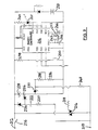
- the electronic circuit of Figure 3 is contained within a housing 201 of a momentary contact switch 200 having a mounting plate 202 and a push plate 20, which acts to close the switch when pressed.
- An light emitting diode (LED) 208 is mounted in the push plate, and a tab 204 operates on air gap switch 206 (see Figure 5) enabling isolation of the controlled circuit independently of any solely electronic circuit, as required by some certification authorities.
- LED light emitting diode
- the circuit itself is based upon the MC68HCO5J1 microcontroller from Motorola, although other suitable microcontrollers will be apparent to those skilled in the art, such as the ST6210 from SGS-Thompson which is specifically designed for use in power control applications and incorporates clamping diodes designed to provide a high degree of transient protection.
- the circuit is connected between line and load terminals 210 and 212 and may be isolated from the terminal 212 by the switch 206.
- the circuit includes a triac 214 connected directly between the switch and the terminal 210.
- the triac 214 When suitable signals are applied to the triac 214 from parallel connected output ports, lines PAO and PA1 of the microcontroller 216, through a current limiting resistor 218, the triac is turned on a short period, 2ms in the example to be described, set by a program controlling the microcontroller, after the beginning of each half cycle of the supply; otherwise it remains turned off.
- the power supply circuit for the microcontroller is also connected across the triac 214, and includes a dropper resistor 220, a capacitor 222 and a zener diode 224 in series so as to produce voltage limited negative going pulse across the diode 224 during at least the short period of the beginning of each negative half-cycle of the supply, which is connected to direct current by a rectifier diode 226 and a reservoir capacitor or equivalent 228.
- One terminal 210 is also connected through a resistor 248 through a pair of resistors 234 and 236 in parallel with a zener diode 230, to the negative supply terminal VSS of the microcontroller 216, forming a potentiometer whose tap is connected to an input port line PB5 of the microcontroller.
- a further input port line PBO is normally pulled up by a resistor 238, but may be pulled down by the momentary contact switch 200.
- Output port lines PA2 and PA3 can sink current through a resistor240 and the LED 201.
- Non-maskable interrupt (NMI) and test terminals of the microcontroller are not used and are grounded, while a reset terminal is connected to a power-on delay circuit consisting of a resistor and a capacitor.
- a crystal 242 in conjunction with capacitors 244 and 246 and a resistor 232 connected to terminals OSC1 and OSC2 provide a clock signal for the micro- controller.
- a rechargeable battery 250 may provide backup power to the microcontroller 216 in the event of a power failure.
- the SCANOFF routine is similar except that the START and END addresses are eight bytes higher.
- a routine is also preferably included which copies the contents of the memory locations to be used to provide the current day's ON and OFF storage locations to alternate locations at the beginning of the day, and restores these contents at the end of the day if none of the locations have been used to store new ON or OFF times, thus avoiding deprogramming of the device if the switch is unused for several days.
- any such activation of the switch will reverse the condition of the device, and will also take it out of the 'automatic' mode.
- the switch In order to place the device in automatic mode, the switch is pressed for at least two seconds, and thereafter, until the switch is again pressed to toggle the state of the device, the microcontroller will change the condition of the device according to the data stored as to switch transitions in the tables for three successive twenty-four hour periods, the data in the tables relating to transitions of the type necessary to reverse the state of the switch being logically ORed to provide a composite switching pattern, and the timing of any transition applied being subjected to a random variance of up to 14 minutes ahead or 15 minutes beyond its nominal type (in this example).
- An additional advantage of this ran- domisation of switching times is that it disguises the fact that transitions are only recorded with a 15 minute resolution (in this example).
- the tables In normal mode, the tables are written to on successive days, one at a time.
- each of'ON' and 'OFF' transitions could be maintained, with additions of transitions of each type beyond a predetermined total, for example eight, resulting in the oldest stored transition being discarded.
- Either system results in the stored pattern of switch transitions being updated on a continuous basis when the switch is in normal use, and in a composite pattern being regenerated during a cycle or automatic operation which is based upon a composite of several cycles (usually 24 hour periods) of normal operation. This is a major improvement over systems in which the automatic operation period is set up during an initialization of the switch, whether the programming of the actual switch transition times is manual or'inherent'.
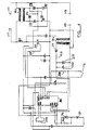
- Figure 4 illustrates the circuit of an alternative embodiment for incorporation in a conventional single or multi-adaptor through which one or more appliances can be connected to an outlet. This resembles the previous embodiment in many respects, and only the differences will be described.
- the unit will incorporate line and neutral pins 110 for insertion into an outlet, and line and neutral pin receptacles 112, duplicated as necessary, for the reception of the pins of appliance plugs.
- a ground pin and connected ground receptacle may be provided but do not form part of the invention.
- the only external difference from a conventional adaptor is the provision of a single pole on/off switch 114, which in the ON position corresponds in function to a two second depression of the switch in the previous embodiment, i.e. it places the device in automatic mode.
- This embodiment does not provide a facility for manual switching of a controlled light or appliance. Instead it senses, when the switch 114 is off, whether or not a controlled appliance is turned on by sensing the passage of current to the receptacles 112 by means of a current sensing transformer TR2, similar to those used for example in ground fault interrupter devices.
- the primary of the transformer is in series with the line receptacle(s) 112, whilst its secondary is connected via a diode D9 and a current limiting resistor R13 to a reservoir capacitor CE2.
- a diode D9 diode
- R13 current limiting resistor
- the bridge rectifier formed by diodes D1 to D4 is supplied from a transformer TR3 across the line and neutral pins 110, thus reducing heat dissipation problems and permitting use of a simplified power supply circuit.
- a rechargeable battery B1 is provided. During normal operation, the battery trickle charges through R12, whilst under power failure or unplugged conditions, the battery powers the microcontroller MC through diode D6.
- a capacitative or non-contact, e.g. optical, switch could be utilized, within the scope of the invention.
Applications Claiming Priority (2)
| Application Number | Priority Date | Filing Date | Title |
|---|---|---|---|
| US919241 | 1992-07-27 | ||
| US07/919,241 US5481452A (en) | 1991-04-19 | 1992-07-27 | Programmable switching unit |
Publications (2)
| Publication Number | Publication Date |
|---|---|
| EP0581555A1 true EP0581555A1 (fr) | 1994-02-02 |
| EP0581555B1 EP0581555B1 (fr) | 1997-10-01 |
Family
ID=25441764
Family Applications (1)
| Application Number | Title | Priority Date | Filing Date |
|---|---|---|---|
| EP19930305878 Expired - Lifetime EP0581555B1 (fr) | 1992-07-27 | 1993-07-26 | Unité de commutation programmable |
Country Status (7)
| Country | Link |
|---|---|
| US (1) | US5481452A (fr) |
| EP (1) | EP0581555B1 (fr) |
| AT (1) | ATE158874T1 (fr) |
| AU (1) | AU667722B2 (fr) |
| CA (1) | CA2101283A1 (fr) |
| DE (1) | DE69314259D1 (fr) |
| HK (1) | HK1003495A1 (fr) |
Cited By (5)
| Publication number | Priority date | Publication date | Assignee | Title |
|---|---|---|---|---|
| WO1997006542A1 (fr) * | 1995-08-09 | 1997-02-20 | 1012384 Ontario Inc. | Interrupteur de commande a fonctions multiples destine a des dispositifs electriques |
| DE19728066C1 (de) * | 1997-07-01 | 1999-01-28 | Thomas Nitsche | Schalterelement und Verfahren zu seiner Steuerung |
| NL1004753C2 (nl) * | 1996-03-16 | 1999-07-13 | Insta Elektro Gmbh & Co Kg | Lichtschakelaar voor aanwezigheidssimulatie. |
| GB2425002A (en) * | 2005-04-04 | 2006-10-11 | Arc Technology Co Ltd | Burglar-proof wireless light adjusting module |
| WO2009027355A3 (fr) * | 2007-08-27 | 2009-05-07 | John Boersting | Modules de commutation servant de protection contre l'effraction |
Families Citing this family (18)
| Publication number | Priority date | Publication date | Assignee | Title |
|---|---|---|---|---|
| US5390324A (en) * | 1992-10-02 | 1995-02-14 | Compaq Computer Corporation | Computer failure recovery and alert system |
| US6356038B2 (en) | 1994-12-14 | 2002-03-12 | Richard A. Bishel | Microcomputer-controlled AC power switch controller and DC power supply method and apparatus |
| US5615107A (en) * | 1995-05-16 | 1997-03-25 | Fiskars Inc. | Power control method and apparatus |
| US6414587B1 (en) | 1998-03-13 | 2002-07-02 | The Chamberlain Group, Inc. | Code learning system for a movable barrier operator |
| US5751224A (en) * | 1995-05-17 | 1998-05-12 | The Chamberlain Group, Inc. | Code learning system for a movable barrier operator |
| US5883816A (en) * | 1995-10-13 | 1999-03-16 | Belanger, Inc. | Interface circuit for processor controlled system and vehicle laundry system utilizing such interface circuit |
| US6078159A (en) | 1999-02-17 | 2000-06-20 | The Chamberlain Group, Inc. | Method and apparatus for programming a logic board from switching power |
| DE19943124A1 (de) * | 1999-09-09 | 2001-03-15 | Bsh Bosch Siemens Hausgeraete | Vorrichtung zur Netzausfallerkennung in einem programmgesteuerten Haushaltgerät |
| GB0029644D0 (en) * | 2000-12-06 | 2001-01-17 | Koninkl Philips Electronics Nv | Method of powering-up battery powered apparatus |
| US6933686B1 (en) | 2003-01-09 | 2005-08-23 | Richard Anthony Bishel | Programmable AC power switch |
| US6903284B2 (en) * | 2003-07-30 | 2005-06-07 | Linda Williams Dunfield | Timed switch control for electric devices |
| FR2878647B1 (fr) * | 2004-11-26 | 2007-02-23 | Delta Dore | Procede de programmation de la duree de temporisation d'une minuterie |
| WO2006080066A1 (fr) * | 2005-01-27 | 2006-08-03 | Fujitsu Limited | Dispositif, procede et programme de calcul d'itineraire |
| DE102006044008A1 (de) * | 2006-09-19 | 2008-03-27 | Conti Temic Microelectronic Gmbh | Schaltungsanordnung zur Spannungsprüfung an einem Schaltungspunkt mit einem Mikrocontroller |
| US8050145B2 (en) * | 2008-02-26 | 2011-11-01 | Leviton Manufacturing Co., Inc. | Wall mounted programmable timer system |
| US7863777B2 (en) * | 2008-03-05 | 2011-01-04 | Gallen Ka Leung Tsui | Low power switching circuit |
| US20130325150A1 (en) * | 2012-06-05 | 2013-12-05 | Henryk Bury | Method for the Operation of a Control Unit and a Control Unit |
| WO2016179655A1 (fr) * | 2015-05-13 | 2016-11-17 | Beyer Peter Ernest | Système d'éclairage avec détecteur de fumée intégré |
Citations (4)
| Publication number | Priority date | Publication date | Assignee | Title |
|---|---|---|---|---|
| DE8702477U1 (fr) * | 1987-02-18 | 1987-05-14 | Lindner Gmbh, Fabrik Elektrischer Lampen Und Apparate, 8600 Bamberg, De | |
| US4695739A (en) * | 1985-10-18 | 1987-09-22 | Pierce Lyle R | Multi-function switch-controlled lamp circuit |
| DE3710850C1 (en) * | 1987-04-01 | 1988-06-30 | Vedder Gmbh Geb | Electrotechnical accessory device |
| FR2618233A1 (fr) * | 1987-07-15 | 1989-01-20 | Cleja Vladimir | Appareil programmable de commutation, notamment pour simulation de presence. |
Family Cites Families (13)
| Publication number | Priority date | Publication date | Assignee | Title |
|---|---|---|---|---|
| US4095139B1 (en) * | 1977-05-18 | 1997-07-08 | Vari Lite Inc | Light control system |
| USRE31848F1 (en) * | 1978-08-28 | 1993-12-28 | Electronic assembly | |
| US4300090A (en) * | 1979-03-02 | 1981-11-10 | Weber Harold J | Direct current power supply |
| US4349748A (en) * | 1979-03-21 | 1982-09-14 | Dynascan Corporation | Timer and power control system |
| US4354120A (en) * | 1979-03-21 | 1982-10-12 | Dynascan Corporation | Daily variability timer |
| US4274045A (en) * | 1979-04-09 | 1981-06-16 | Richard Goldstein | Power supply and control circuit for series connected controller |
| US4593234A (en) * | 1982-05-11 | 1986-06-03 | Yang Jerry S C | Programmable apparatus for controlling illuminating lamps |
| JPS58222310A (ja) * | 1982-06-21 | 1983-12-24 | Omron Tateisi Electronics Co | 状態パタ−ン比較機能を備えたプログラマブル・コントロ−ラ |
| US4521843A (en) * | 1982-08-16 | 1985-06-04 | Intermatic Incorporated | Programmable wall switch for controlling lighting times and loads |
| US4570216A (en) * | 1983-02-10 | 1986-02-11 | Brightmond Company Limited | Programmable switch |
| CH655587B (fr) * | 1983-09-22 | 1986-04-30 | ||
| US4672232A (en) * | 1986-02-10 | 1987-06-09 | Pittway Corporation | Microprocessor operated timing controller |
| US5258656A (en) * | 1991-07-25 | 1993-11-02 | Pawlick William F | Electronic on/off timer apparatus and method incorporating predetermined time delay intervals |
-
1992
- 1992-07-27 US US07/919,241 patent/US5481452A/en not_active Expired - Fee Related
-
1993
- 1993-07-26 DE DE69314259T patent/DE69314259D1/de not_active Expired - Lifetime
- 1993-07-26 AU AU42170/93A patent/AU667722B2/en not_active Ceased
- 1993-07-26 EP EP19930305878 patent/EP0581555B1/fr not_active Expired - Lifetime
- 1993-07-26 AT AT93305878T patent/ATE158874T1/de active
- 1993-07-26 CA CA 2101283 patent/CA2101283A1/fr not_active Abandoned
-
1998
- 1998-03-26 HK HK98102577A patent/HK1003495A1/xx unknown
Patent Citations (4)
| Publication number | Priority date | Publication date | Assignee | Title |
|---|---|---|---|---|
| US4695739A (en) * | 1985-10-18 | 1987-09-22 | Pierce Lyle R | Multi-function switch-controlled lamp circuit |
| DE8702477U1 (fr) * | 1987-02-18 | 1987-05-14 | Lindner Gmbh, Fabrik Elektrischer Lampen Und Apparate, 8600 Bamberg, De | |
| DE3710850C1 (en) * | 1987-04-01 | 1988-06-30 | Vedder Gmbh Geb | Electrotechnical accessory device |
| FR2618233A1 (fr) * | 1987-07-15 | 1989-01-20 | Cleja Vladimir | Appareil programmable de commutation, notamment pour simulation de presence. |
Cited By (7)
| Publication number | Priority date | Publication date | Assignee | Title |
|---|---|---|---|---|
| US5753983A (en) * | 1992-06-16 | 1998-05-19 | 1012384 Ontario, Inc. | Multi-function control switch for electrically operating devices |
| WO1997006542A1 (fr) * | 1995-08-09 | 1997-02-20 | 1012384 Ontario Inc. | Interrupteur de commande a fonctions multiples destine a des dispositifs electriques |
| NL1004753C2 (nl) * | 1996-03-16 | 1999-07-13 | Insta Elektro Gmbh & Co Kg | Lichtschakelaar voor aanwezigheidssimulatie. |
| DE19728066C1 (de) * | 1997-07-01 | 1999-01-28 | Thomas Nitsche | Schalterelement und Verfahren zu seiner Steuerung |
| GB2425002A (en) * | 2005-04-04 | 2006-10-11 | Arc Technology Co Ltd | Burglar-proof wireless light adjusting module |
| WO2009027355A3 (fr) * | 2007-08-27 | 2009-05-07 | John Boersting | Modules de commutation servant de protection contre l'effraction |
| EP2584872A1 (fr) * | 2007-08-27 | 2013-04-24 | Jensen, John Børsting | Module de commutation destiné à être utilisé comme protection contre l'effraction |
Also Published As
| Publication number | Publication date |
|---|---|
| DE69314259D1 (de) | 1997-11-06 |
| ATE158874T1 (de) | 1997-10-15 |
| CA2101283A1 (fr) | 1994-01-28 |
| EP0581555B1 (fr) | 1997-10-01 |
| US5481452A (en) | 1996-01-02 |
| AU667722B2 (en) | 1996-04-04 |
| HK1003495A1 (en) | 1998-10-30 |
| AU4217093A (en) | 1994-02-03 |
Similar Documents
| Publication | Publication Date | Title |
|---|---|---|
| EP0581555B1 (fr) | Unité de commutation programmable | |
| US5323307A (en) | Power management and automation system | |
| US5742466A (en) | Power outlet device with multiple individual timer controlled receptacles | |
| US4964058A (en) | Power management and automation system | |
| US20150061546A1 (en) | Two-outlet digital timer | |
| JPS62118760A (ja) | 負荷制御システム | |
| US5317632A (en) | Timed telephone silencer. (telephone silencer with timer function) | |
| AU657892B2 (en) | Computer-controlled circuit breaker energy management arrangement having reliable memory and clock | |
| CA1205853A (fr) | Commande electronique pour lampe | |
| US4198574A (en) | Timing control circuit | |
| US6798631B1 (en) | Convenience safety timer | |
| US4777384A (en) | Source voltage triggered timer | |
| US5138185A (en) | Electrical backup interface device having low power output | |
| US8963731B1 (en) | Electrical outlet unit | |
| US5461288A (en) | Power management device for large electronic flash units | |
| AU2010100961A4 (en) | A control device | |
| CN210517452U (zh) | 一种自动识别输入电压的电气箱 | |
| US5495385A (en) | Fully automatic, photosensor-controlled time switch device | |
| US10224907B2 (en) | Control of generator exerciser timers | |
| GB2256101A (en) | Power supply alarm with indication of failure duration | |
| GB2199705A (en) | An electrical plug incorporating a time switch | |
| US11610749B2 (en) | Programmable timer outlet | |
| JPH0311485Y2 (fr) | ||
| CN2205020Y (zh) | Led数字钟自控多功能电源插座 | |
| GB2245994A (en) | Time switch |
Legal Events
| Date | Code | Title | Description |
|---|---|---|---|
| PUAI | Public reference made under article 153(3) epc to a published international application that has entered the european phase |
Free format text: ORIGINAL CODE: 0009012 |
|
| AK | Designated contracting states |
Kind code of ref document: A1 Designated state(s): AT BE CH DE ES FR GB IT LI NL |
|
| 17P | Request for examination filed |
Effective date: 19940722 |
|
| 17Q | First examination report despatched |
Effective date: 19951120 |
|
| GRAG | Despatch of communication of intention to grant |
Free format text: ORIGINAL CODE: EPIDOS AGRA |
|
| GRAH | Despatch of communication of intention to grant a patent |
Free format text: ORIGINAL CODE: EPIDOS IGRA |
|
| GRAH | Despatch of communication of intention to grant a patent |
Free format text: ORIGINAL CODE: EPIDOS IGRA |
|
| GRAA | (expected) grant |
Free format text: ORIGINAL CODE: 0009210 |
|
| AK | Designated contracting states |
Kind code of ref document: B1 Designated state(s): AT BE CH DE ES FR GB IT LI NL SE |
|
| PG25 | Lapsed in a contracting state [announced via postgrant information from national office to epo] |
Ref country code: NL Free format text: LAPSE BECAUSE OF FAILURE TO SUBMIT A TRANSLATION OF THE DESCRIPTION OR TO PAY THE FEE WITHIN THE PRESCRIBED TIME-LIMIT Effective date: 19971001 Ref country code: LI Free format text: LAPSE BECAUSE OF FAILURE TO SUBMIT A TRANSLATION OF THE DESCRIPTION OR TO PAY THE FEE WITHIN THE PRESCRIBED TIME-LIMIT Effective date: 19971001 Ref country code: IT Free format text: LAPSE BECAUSE OF FAILURE TO SUBMIT A TRANSLATION OF THE DESCRIPTION OR TO PAY THE FEE WITHIN THE PRE;WARNING: LAPSES OF ITALIAN PATENTS WITH EFFECTIVE DATE BEFORE 2007 MAY HAVE OCCURRED AT ANY TIME BEFORE 2007. THE CORRECT EFFECTIVE DATE MAY BE DIFFERENT FROM THE ONE RECORDED.SCRIBED TIME-LIMIT Effective date: 19971001 Ref country code: FR Free format text: LAPSE BECAUSE OF FAILURE TO SUBMIT A TRANSLATION OF THE DESCRIPTION OR TO PAY THE FEE WITHIN THE PRESCRIBED TIME-LIMIT Effective date: 19971001 Ref country code: ES Free format text: THE PATENT HAS BEEN ANNULLED BY A DECISION OF A NATIONAL AUTHORITY Effective date: 19971001 Ref country code: CH Free format text: LAPSE BECAUSE OF FAILURE TO SUBMIT A TRANSLATION OF THE DESCRIPTION OR TO PAY THE FEE WITHIN THE PRESCRIBED TIME-LIMIT Effective date: 19971001 Ref country code: BE Free format text: LAPSE BECAUSE OF FAILURE TO SUBMIT A TRANSLATION OF THE DESCRIPTION OR TO PAY THE FEE WITHIN THE PRESCRIBED TIME-LIMIT Effective date: 19971001 Ref country code: AT Free format text: LAPSE BECAUSE OF FAILURE TO SUBMIT A TRANSLATION OF THE DESCRIPTION OR TO PAY THE FEE WITHIN THE PRESCRIBED TIME-LIMIT Effective date: 19971001 |
|
| REF | Corresponds to: |
Ref document number: 158874 Country of ref document: AT Date of ref document: 19971015 Kind code of ref document: T |
|
| REG | Reference to a national code |
Ref country code: CH Ref legal event code: EP |
|
| RAP2 | Party data changed (patent owner data changed or rights of a patent transferred) |
Owner name: MINDER RESEARCH CORPORATION |
|
| RIN2 | Information on inventor provided after grant (corrected) |
Free format text: SIMMONS, ROBERT G. |
|
| REF | Corresponds to: |
Ref document number: 69314259 Country of ref document: DE Date of ref document: 19971106 |
|
| NLT2 | Nl: modifications (of names), taken from the european patent patent bulletin |
Owner name: MINDER RESEARCH CORPORATION |
|
| RBV | Designated contracting states (corrected) |
Designated state(s): AT BE CH DE ES FR GB IT LI NL SE |
|
| K2C1 | Correction of patent specification (title page) published |
Effective date: 19971001 |
|
| PG25 | Lapsed in a contracting state [announced via postgrant information from national office to epo] |
Ref country code: DE Free format text: LAPSE BECAUSE OF FAILURE TO SUBMIT A TRANSLATION OF THE DESCRIPTION OR TO PAY THE FEE WITHIN THE PRESCRIBED TIME-LIMIT Effective date: 19980103 |
|
| EN | Fr: translation not filed | ||
| NLV1 | Nl: lapsed or annulled due to failure to fulfill the requirements of art. 29p and 29m of the patents act | ||
| PG25 | Lapsed in a contracting state [announced via postgrant information from national office to epo] |
Ref country code: SE Free format text: LAPSE BECAUSE OF FAILURE TO SUBMIT A TRANSLATION OF THE DESCRIPTION OR TO PAY THE FEE WITHIN THE PRESCRIBED TIME-LIMIT Effective date: 19980310 |
|
| REG | Reference to a national code |
Ref country code: CH Ref legal event code: PL |
|
| PLBE | No opposition filed within time limit |
Free format text: ORIGINAL CODE: 0009261 |
|
| STAA | Information on the status of an ep patent application or granted ep patent |
Free format text: STATUS: NO OPPOSITION FILED WITHIN TIME LIMIT |
|
| 26N | No opposition filed | ||
| REG | Reference to a national code |
Ref country code: GB Ref legal event code: IF02 |
|
| PGFP | Annual fee paid to national office [announced via postgrant information from national office to epo] |
Ref country code: GB Payment date: 20030728 Year of fee payment: 11 |
|
| PG25 | Lapsed in a contracting state [announced via postgrant information from national office to epo] |
Ref country code: GB Free format text: LAPSE BECAUSE OF NON-PAYMENT OF DUE FEES Effective date: 20040726 |
|
| GBPC | Gb: european patent ceased through non-payment of renewal fee |
Effective date: 20040726 |