EP0581237A1 - Device for air conditioning - Google Patents
Device for air conditioning Download PDFInfo
- Publication number
- EP0581237A1 EP0581237A1 EP93111967A EP93111967A EP0581237A1 EP 0581237 A1 EP0581237 A1 EP 0581237A1 EP 93111967 A EP93111967 A EP 93111967A EP 93111967 A EP93111967 A EP 93111967A EP 0581237 A1 EP0581237 A1 EP 0581237A1
- Authority
- EP
- European Patent Office
- Prior art keywords
- air
- heat exchanger
- line
- rooms
- compressor
- Prior art date
- Legal status (The legal status is an assumption and is not a legal conclusion. Google has not performed a legal analysis and makes no representation as to the accuracy of the status listed.)
- Withdrawn
Links
Images
Classifications
-
- B—PERFORMING OPERATIONS; TRANSPORTING
- B61—RAILWAYS
- B61D—BODY DETAILS OR KINDS OF RAILWAY VEHICLES
- B61D27/00—Heating, cooling, ventilating, or air-conditioning
- B61D27/0018—Air-conditioning means, i.e. combining at least two of the following ways of treating or supplying air, namely heating, cooling or ventilating
-
- B—PERFORMING OPERATIONS; TRANSPORTING
- B60—VEHICLES IN GENERAL
- B60H—ARRANGEMENTS OF HEATING, COOLING, VENTILATING OR OTHER AIR-TREATING DEVICES SPECIALLY ADAPTED FOR PASSENGER OR GOODS SPACES OF VEHICLES
- B60H1/00—Heating, cooling or ventilating [HVAC] devices
- B60H1/32—Cooling devices
-
- B—PERFORMING OPERATIONS; TRANSPORTING
- B64—AIRCRAFT; AVIATION; COSMONAUTICS
- B64D—EQUIPMENT FOR FITTING IN OR TO AIRCRAFT; FLIGHT SUITS; PARACHUTES; ARRANGEMENTS OR MOUNTING OF POWER PLANTS OR PROPULSION TRANSMISSIONS IN AIRCRAFT
- B64D13/00—Arrangements or adaptations of air-treatment apparatus for aircraft crew or passengers, or freight space, or structural parts of the aircraft
- B64D13/06—Arrangements or adaptations of air-treatment apparatus for aircraft crew or passengers, or freight space, or structural parts of the aircraft the air being conditioned
- B64D2013/0603—Environmental Control Systems
- B64D2013/0688—Environmental Control Systems with means for recirculating cabin air
-
- F—MECHANICAL ENGINEERING; LIGHTING; HEATING; WEAPONS; BLASTING
- F25—REFRIGERATION OR COOLING; COMBINED HEATING AND REFRIGERATION SYSTEMS; HEAT PUMP SYSTEMS; MANUFACTURE OR STORAGE OF ICE; LIQUEFACTION SOLIDIFICATION OF GASES
- F25B—REFRIGERATION MACHINES, PLANTS OR SYSTEMS; COMBINED HEATING AND REFRIGERATION SYSTEMS; HEAT PUMP SYSTEMS
- F25B9/00—Compression machines, plants or systems, in which the refrigerant is air or other gas of low boiling point
- F25B9/002—Compression machines, plants or systems, in which the refrigerant is air or other gas of low boiling point characterised by the refrigerant
- F25B9/004—Compression machines, plants or systems, in which the refrigerant is air or other gas of low boiling point characterised by the refrigerant the refrigerant being air
-
- Y—GENERAL TAGGING OF NEW TECHNOLOGICAL DEVELOPMENTS; GENERAL TAGGING OF CROSS-SECTIONAL TECHNOLOGIES SPANNING OVER SEVERAL SECTIONS OF THE IPC; TECHNICAL SUBJECTS COVERED BY FORMER USPC CROSS-REFERENCE ART COLLECTIONS [XRACs] AND DIGESTS
- Y02—TECHNOLOGIES OR APPLICATIONS FOR MITIGATION OR ADAPTATION AGAINST CLIMATE CHANGE
- Y02T—CLIMATE CHANGE MITIGATION TECHNOLOGIES RELATED TO TRANSPORTATION
- Y02T30/00—Transportation of goods or passengers via railways, e.g. energy recovery or reducing air resistance
-
- Y—GENERAL TAGGING OF NEW TECHNOLOGICAL DEVELOPMENTS; GENERAL TAGGING OF CROSS-SECTIONAL TECHNOLOGIES SPANNING OVER SEVERAL SECTIONS OF THE IPC; TECHNICAL SUBJECTS COVERED BY FORMER USPC CROSS-REFERENCE ART COLLECTIONS [XRACs] AND DIGESTS
- Y02—TECHNOLOGIES OR APPLICATIONS FOR MITIGATION OR ADAPTATION AGAINST CLIMATE CHANGE
- Y02T—CLIMATE CHANGE MITIGATION TECHNOLOGIES RELATED TO TRANSPORTATION
- Y02T50/00—Aeronautics or air transport
- Y02T50/50—On board measures aiming to increase energy efficiency
Definitions
- the invention relates to a device for air conditioning of rooms with at least one compressor for compressing outside air and at least one intercooler, with a downstream expansion machine, in particular expansion turbine, for recovering mechanical energy and with a mixing chamber for admixing recirculated exhaust air from the rooms to the outlet of the Air leaving the expansion machine before it is sent to the rooms.
- the invention is particularly intended for recreation rooms for people or animals in rail vehicles or other land vehicles, although it can also be used on ships or for stationary operation.
- the present invention is based on the object of proposing a device for the air conditioning of rooms in which the quality or efficiency is increased to such an extent that the values of the overall system approach those of evaporator systems.
- This object is achieved in a device of the type mentioned in that the amount of air passed through the compressor, intercooler and the expansion machine is dimensioned for optimum cooling performance, and that additional air is supplied to the mixing chamber if necessary by an additional fan.
- a further improvement in the overall efficiency can be achieved in that the additional outside air is supplied via a first heat exchanger, by means of which the outside air is pre-cooled (in cooling mode) or preheated (in heating mode) by means of exhaust air from the rooms, depending on the operating state of the device.
- the additional air introduced by means of the additional fan is precooled in the first heat exchanger by exhaust air from the rooms to be air-conditioned, so that the efficiency of the overall system, which is already favorable due to the optimization of the device, is further increased.
- a particularly advantageous device is characterized in that a first compressor for precompression the outside air and a second compressor for further compression as well as intermediate heat exchangers for intermediate cooling are provided, and that the second compressor is driven by the expansion machine.
- the expansion machine is advantageously preceded by a condensation heat exchanger which separates out condensation water.
- the condensation heat exchanger is fed with the expanded air from the expansion machine.
- the water of condensation occurring in the condenser heat exchanger in the separator can preferably be used to improve the efficiency by injecting it into the exhaust air supplied to the first heat exchanger.
- An injection of condensation water can also take place in the heat exchanger downstream of the second compressor if this is cooled by means of the outside air supplied.
- the heat exchanger is advantageously divided into two sections, through which the compressed air flows in succession. Condensation water (or extraneous water) is then injected into the outside air supplied to the second (colder) section of the heat exchanger.
- the exhaust air passed through the first heat exchanger (for pre-cooling the fresh air supplied via the additional fan) is still so low that it can then be passed through a second heat exchanger for intermediate cooling of the air pre-compressed by the first compressor.
- the recirculating exhaust air from the rooms of the mixing chamber for dehumidification is fed via a (further) condensation heat exchanger, which is fed with the treated air from the expansion machine, condensation water in a separator is deposited.
- pre-compressed and thus heated outside air can be introduced from the outlet of the first compressor into the mixing chamber via a temperature control valve.
- the device according to the invention makes it possible in a simple manner to suddenly keep excess pressures that occur in the outside air briefly or over longer periods of time from the rooms to be air-conditioned. This takes place in that at least some of the inflows and outflows of the rooms to be air-conditioned which are connected to the outside air can be partially or completely closed off via pressure protection valves during excess pressure in the outside air. This is particularly important when using the device according to the invention for the air conditioning of railway trains when passing through tunnels.
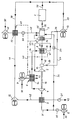
- the drawing shows a schematic diagram of a device for air conditioning rooms according to the invention.
- a first compressor 2 which pre-compresses outside air 30 and supplies it to the inlet of a second compressor 4 via a line 31 and a heat exchanger 3 for the purpose of intermediate cooling.
- this second compressor 4 which is driven by an expansion machine 5 via a shaft 16, the precompressed and intercooled ambient air is compressed further and precooled via a further heat exchanger 6.
- Outside air 30 serves as cooling medium for this heat exchanger 6, which is led through the heat exchanger 6 by a fan 7 and discharged into the open air 43.
- the precooled and compressed air flows via a line 34, a condensation heat exchanger 8 and a line 35 to the inlet of the expansion machine 5 and leaves it via an outlet 36 with a pressure which in the present case is slightly above the ambient pressure.
- the temperature of the air leaving outlet 36 is well below 0 ° C.
- the condensation heat exchanger 8 serves to dehumidify the compressed air which has been precooled by the heat exchanger 6, which takes place through the cold air coming from the outlet 36 of the expansion machine 5.
- Condensation water (dashed line 47) is separated in a separator 18 of the condensation heat exchanger 8. The air cooled and dehumidified in the condensation heat exchanger 8 reaches the inlet of the expansion machine 5 via line 35.
- the temperature of the air heated in the condensation heat exchanger 8 is still considerably below the ambient temperature and passes as conditioned (cooled and dehumidified) air via a line 37 and via a further condensation heat exchanger 14 into a mixing chamber 9 via line 37
- the heat exchanger 10 fulfills a double function.
- the outside temperature acts as a pre-cooler for the fresh air, while at lower outside temperatures, that is to say in the case of heating, the heat exchanger 10 serves for preheating.
- the air mixed in the mixing chamber 9 then passes through a filter 25 and a line 38 into the rooms 1 to be air-conditioned.
- the exhaust air exiting through the line 39 of the rooms 1 to be air-conditioned is not only recirculated to the mixing chamber 9, but also passes outside via the heat exchanger 10 (or directly), a line 41, a fan 12, a line 42 and via the heat exchanger 3 43.
- the exhaust air thus causes a pre-cooling of the outside air 30 passed through the heat exchanger 10, which is fed to the mixing chamber 9 as fresh air and, moreover, the exhaust air supplied via the line 41 to the heat exchanger 3 is so cold, however, that the means by the first compressor 2 pre-compressed air (line 31) can be intercooled more intensively than if only outside air were used for this.
- the exhaust air (line 39) in the heat exchangers 10 and 3 the efficiency of the device is significantly increased.
- the condensation heat exchanger 14 with a separator 17 inserted between line 37 and the mixing chamber 9 serves to dehumidify the recirculating exhaust air (line 39), which can be necessary in particular when many people are in rooms 1 to be air-conditioned.
- the dehumidification in the condensation heat exchanger 8 with separator 18 may not be sufficient here.
- the separator 17 there is now further condensation water which is fed into a common line system (dashed line 47).
- the condensation water (line 47) obtained in the condensation heat exchangers 8 and 14 can now be used to further increase the efficiency of the system.
- the dashed line of line 47 shows, condensation water is injected into the exhaust air leading to the heat exchanger 10, on the one hand, since the relative air humidity of the exhaust air coming from room 1 is normally approx.
- the humidity of the exhaust air supplied to the heat exchanger can, however, be increased to 100%, so that the evaporation results in a much more intensive cooling in the heat exchanger 10.
- water of condensation can be injected into the heat exchanger 6 in a suitable manner in order to effect a more effective pre-cooling of the compressed air.
- the heat exchanger 6 is divided into two sections 6a and 6b, which are connected in series with respect to the compressed air. Outside sections 30 are fed in parallel to both sections 6a and 6b via the fan 7. In the colder section 6b of the heat exchanger 6, the supplied outside air is supplied with condensation water (line 47) by injection in order to significantly improve the cooling effect.
- a pressure protection system can be implemented in a simple manner, which keeps pressure surges away from the rooms 1 to be air-conditioned (passenger cabins) during tunnel journeys or train encounters.
- the inflows and outflows to the rooms 1 to be air-conditioned namely the inflow in line 45 and the outflow in line 42, are protected by pressure protection valves 22, 21 which are partially or completely closed if and for as long as pressure fluctuations in the Outside air occur.
- a pressure protection valve 20 is also provided at the outlet of the first compressor 2, but this must be of a special design since the outlet of the compressor 2 is not simply closed, but is expediently deflected into the open.
- exhaust air from the line 39 is passed via a line 44 via a quantity limiting valve 23 into an additional mixing chamber 15, around the coming from the outlet of the expansion machine 5 Preheat the air so far that the danger of icing is eliminated.
- a bypass path 46 (for heating operation) is provided from the outlet of the first compressor 2 to the mixing chamber 9 in order to supply preheated air due to the compression, bypassing the other structural units .
- the supply takes place via a temperature control valve 24.
- the expansion machine provided with the reference number 5, which drives the second compressor 4 via the shaft 16, is preferably an expansion turbine in the present example.
- the expansion machine 5 does not drive the second compressor 4, but rather a few or more fans.
- the device works with two-stage compression by the two compressors 2 and 4, it is of course also possible to provide only one compressor. In such a case, the mechanical output power of the expansion machine 5 can then either be used to additionally drive the single compressor, or it drives auxiliary units.
Abstract
Description
Die Erfindung betrifft eine Vorrichtung zur Klimatisierung von Räumen mit mindestens einem Kompressor zur Verdichtung von Außenluft und mindestens einem Zwischenkühler, mit einer nachgeschalteten Expansionsmaschine, insbesondere Expansionsturbine, zur Rückgewinnung mechanischer Energie und mit einer Mischkammer zum Beimischen rezirkulierter Abluft aus den Räumen zu der den Auslaß der Expansionsmaschine verlassenden Luft, bevor diese den Räumen zugeleitet wird. Die Erfindung ist insbesondere für Aufenthaltsräume für Menschen oder Tiere in Schienenfahrzeugen oder anderen Landfahrzeugen bestimmt, obwohl ein Einsatz auch auf Schiffen oder für den stationären Betrieb möglich ist.The invention relates to a device for air conditioning of rooms with at least one compressor for compressing outside air and at least one intercooler, with a downstream expansion machine, in particular expansion turbine, for recovering mechanical energy and with a mixing chamber for admixing recirculated exhaust air from the rooms to the outlet of the Air leaving the expansion machine before it is sent to the rooms. The invention is particularly intended for recreation rooms for people or animals in rail vehicles or other land vehicles, although it can also be used on ships or for stationary operation.
Wie bereits aus dem Aufsatz "Kaltluftkältemaschinen nach dem Joule-Prozeß" in der Zeitschrift Klima-Kälte-Heizung 5/1990, Seiten 206 bis 211, hervorgeht, nimmt im Rahmen der Suche nach alternativen Kältetechnologien zur Substitution von Kaltdampfprozessen mit vollhalogenierten Fluorchlorkohlenwasserstoffen (FCKW) das Interesse am Kaltluftprozeß wegen der Unschädlichkeit des Kältemittels Luft erneut zu. Solche Anlagen sind bisher insbesondere im Bereich der Flugzeugklimatisierung bekannt geworden, wo es vor allem auf geringes Gewicht der Anlage ankommt und Turboverdichter im Strahltriebwerk bereits vorhanden sind.As can already be seen from the article "Cold air chillers according to the Joule process" in the magazine Klima-Kühl-Heizung 5/1990, pages 206 to 211, the search for alternative refrigeration technologies for the substitution of cold steam processes with fully halogenated chlorofluorocarbons (CFCs) the interest in the cold air process due to the harmlessness of the refrigerant air increases again. Systems of this type have hitherto become known in particular in the field of aircraft air conditioning, where the low weight of the system is particularly important and turbo compressors are already present in the jet engine.
Außerdem sind bereits Untersuchungen von Kaltluft-Kälteprozessen für den Einsatz in zu klimatisierenden Schienenfahrzeugen, insbesondere Güterwagen bekannt geworden (Wissenschaftliche Zeitschrift der Hochschule für Verkehrswesen "Friedrich List" in Dresden, 27 (1980) Heft 1, Seiten 35 bis 41). Die dort beschriebenen Kaltluftanlagen arbeiten nach einem offenen Prozeß unter Verwendung eines Verdichters, eines Wärmeübertragers, einer Expansionsturbine und einer Mischkammer. Eine ähnliche Vorrichtung ist aus der DE-OS 40 05 698 bekannt. Die Gütegrade solcher Anlagen liegen jedoch deutlich niedriger als bei den bisher mit FCKW arbeitenden Verdampferanlagen, so daß Anlagen nach dem Kaltluftprozeß sich bisher wegen des hohen Leistungsverbrauches nicht durchsetzen konnten.In addition, studies of cold air cooling processes for use in rail vehicles to be air-conditioned, in particular freight cars, have already become known (scientific journal of the University of Transportation "Friedrich List" in Dresden, 27 (1980) Issue 1,
Schließlich ist es aus dem Buch "Wärmerückgewinnung in raumtechnischen Anlagen", 2. Auflage, Verlag C.F. Müller, Karlsruhe, 1980, S. 97-107, bekannt, in Heizungsanlagen die Abluft von Räumen sowie die zugeführte Zuluft über einen Wärmetauscher zwecks Energierückgewinnung zu leiten.Finally, it is from the book "Heat recovery in spatial systems", 2nd edition, C.F. Müller, Karlsruhe, 1980, pp. 97-107, known to direct the exhaust air from rooms and the supplied supply air through a heat exchanger for the purpose of energy recovery in heating systems.
Der vorliegenden Erfindung liegt die Aufgabe zugrunde, eine Vorrichtung zur Klimatisierung von Räumen vorzuschlagen, bei der Gütegrad bzw. Wirkungsgrad dermaßen erhöht wird, daß sich die Werte der Gesamtanlage denen von Verdampferanlagen nähern.The present invention is based on the object of proposing a device for the air conditioning of rooms in which the quality or efficiency is increased to such an extent that the values of the overall system approach those of evaporator systems.
Diese Aufgabe wird bei einer Vorrichtung der eingangs genannten Art dadurch gelöst, daß die durch den Kompressor, Zwischenkühler und die Expansionsmaschine geführte Luftmenge für eine optimale Kälteleistung bemessen ist, und daß der Mischkammer durch einen Zusatzlüfter bei Bedarf zusätzlich Außenluft zugeführt wird.This object is achieved in a device of the type mentioned in that the amount of air passed through the compressor, intercooler and the expansion machine is dimensioned for optimum cooling performance, and that additional air is supplied to the mixing chamber if necessary by an additional fan.
Durch diese Maßnahme werden dadurch Verbesserungen möglich, weil der Kompressor und der Luftaufbereitungsanteil der Anlage für Kälteleistung optimiert werden können, ohne daß durch einen erhöhten Luftdurchsatz durch den Kompressor entsprechend dem gewünschten Frischluftanteil im Verhältnis zur rezirkulierten Luft diese optimale Einstellung gestört werden müßte. Mit anderen Worten: Wenn die Anlage bei voller Kühlleistung über den Kompressor den erforderlichen Frischluftanteil im Verhältnis der rezirkulierten Luft in den zu klimatisierenden Räumen bereitstellt, kann bei einer Drosselung der Kühlleistung, z.B. bei höherer Außentemperatur, die Anlage mit gutem Wirkungsgrad weiterbetrieben werden, weil dann zusätzliche Frischluft über den Zusatzlüfter zugeführt werden kann.This measure makes improvements possible because the compressor and the air treatment part of the system can be optimized for cooling capacity without this optimal setting having to be disturbed by an increased air flow through the compressor in accordance with the desired fresh air proportion in relation to the recirculated air. In other words: If the system provides the required proportion of fresh air in the ratio of the recirculated air in the rooms to be air-conditioned at full cooling capacity via the compressor, the cooling capacity, e.g. at higher outside temperatures, the system can continue to be operated with good efficiency, because additional fresh air can then be supplied via the additional fan.
Eine weitere Verbesserung des Gesamtwirkungsgrades kann dadurch erreicht werden, daß die zusätzliche Außenluft über einen ersten Wärmetauscher zugeführt wird, durch den die Außenluft mittels Abluft aus den Räumen je nach Betriebszustand der Vorrichtung vorgekühlt (bei Kühlbetrieb) oder vorgewärmt (bei Heizbetrieb) wird. Hierdurch wird die mittels des Zusatzlüfters eingeführte Zusatzluft in dem ersten Wärmetauscher durch Abluft aus den zu klimatisierenden Räumen vorgekühlt, so daß sich der durch die Optimierung der Vorrichtung schon günstige Wirkungsgrad der Gesamtanlage noch weiter erhöht.A further improvement in the overall efficiency can be achieved in that the additional outside air is supplied via a first heat exchanger, by means of which the outside air is pre-cooled (in cooling mode) or preheated (in heating mode) by means of exhaust air from the rooms, depending on the operating state of the device. As a result, the additional air introduced by means of the additional fan is precooled in the first heat exchanger by exhaust air from the rooms to be air-conditioned, so that the efficiency of the overall system, which is already favorable due to the optimization of the device, is further increased.
Obwohl die bei der Vorrichtung vorgesehene Expansionsmaschine auch zum mechanischen Antrieb anderer Einrichtungen, z.B. von Lüftern, verwendet werden kann, ist eine besonders vorteilhafte Vorrichtung dadurch gekennzeichnet, daß ein erster Kompressor zur Vorverdichtung der Außenluft und ein zweiter Kompressor zur weiteren Verdichtung sowie zwischengeschaltete Wärmetauscher zur Zwischenkühlung vorgesehen sind, und daß der zweite Kompressor durch die Expansionsmaschine angetrieben wird.Although the expansion machine provided in the device can also be used to mechanically drive other devices, for example fans, a particularly advantageous device is characterized in that a first compressor for precompression the outside air and a second compressor for further compression as well as intermediate heat exchangers for intermediate cooling are provided, and that the second compressor is driven by the expansion machine.
Um eine Entfeuchtung der zugeführten Außenluft sowie eine Vereisung aufgrund der niedrigen Temperaturen am Auslaß der Expansionsmaschine zu verhindern, ist zweckmäßigerweise der Expansionsmaschine ein Kondensations-Wärmetauscher vorgeschaltet, der Kondensationswasser abscheidet. Der Kondensations-Wärmetauscher wird hierbei mit der expandierten Luft aus der Expansionsmaschine beschickt.In order to prevent dehumidification of the supplied outside air and icing due to the low temperatures at the outlet of the expansion machine, the expansion machine is advantageously preceded by a condensation heat exchanger which separates out condensation water. The condensation heat exchanger is fed with the expanded air from the expansion machine.
Das im Kondensations-Wärmetauscher im Abscheider anfallende Kondensationswasser kann vorzugsweise zur Verbesserung des Wirkungsgrades herangezogen werden, indem es in die dem ersten Wärmetauscher zugeführte Abluft eingespritzt wird. Eine Einspritzung von Kondensationswasser kann auch in den dem zweiten Kompressor nachgeschalteten Wärmetauscher erfolgen, wenn dieser mittels zugeführter Außenluft gekühlt wird. Der Wärmetauscher ist zweckmäßigerweise in zwei Abschnitte unterteilt, die nacheinander von derverdichteten Luft durchströmt werden. In die dem zweiten (kälteren) Abschnitt des Wärmetauschers zugeführten Außenluft wird dann Kondensationswasser (oder Fremdwasser) eingespritzt.The water of condensation occurring in the condenser heat exchanger in the separator can preferably be used to improve the efficiency by injecting it into the exhaust air supplied to the first heat exchanger. An injection of condensation water can also take place in the heat exchanger downstream of the second compressor if this is cooled by means of the outside air supplied. The heat exchanger is advantageously divided into two sections, through which the compressed air flows in succession. Condensation water (or extraneous water) is then injected into the outside air supplied to the second (colder) section of the heat exchanger.
Für den Fall, daß kein Kondensations-Wärmetauscher vorhanden ist oder aufgrund zu trockener Außenluft kaum Kondensationswasser abgeschieden wird, ist es auch möglich, Fremdwasser einzuspritzen.In the event that there is no condensation heat exchanger or hardly any condensation water is separated due to too dry outside air, it is also possible to inject extraneous water.
Die über den ersten Wärmetauscher geführte Abluft (zum Vorkühlen der über den Zusatzlüfter zugeführten Frischluft) hat noch eine so niedrige Temperatur, daß sie anschließend über einen zweiten Wärmetauscher zwecks Zwischenkühlung der durch den ersten Kompressor vorverdichteten Luft geführt werden kann.The exhaust air passed through the first heat exchanger (for pre-cooling the fresh air supplied via the additional fan) is still so low that it can then be passed through a second heat exchanger for intermediate cooling of the air pre-compressed by the first compressor.
Auch wenn die aufbereitete Luft bereits vor dem Entspannen entfeuchtet wird, so ist es dennoch möglich, daß in den zu klimatisierenden Räumen, z.B. aufgrund vieler anwesender Personen, die Luft zu feucht wird. Aus diesem Grunde ist gemäß einer vorteilhaften Ausgestaltung der Erfindung vorgesehen, daß die rezirkulierende Abluft aus den Räumen der Mischkammer zur Entfeuchtung über einen (weiteren) Kondensations-Wärmetauscher zugeführt wird, der mit der aufbereiteten Luft aus der Expansionsmaschine beschickt wird, wobei in einem Abscheider Kondensationswasser abgeschieden wird.Even if the treated air is already dehumidified before relaxing, it is still possible that in the rooms to be air-conditioned, e.g. due to many people present, the air becomes too humid. For this reason, it is provided according to an advantageous embodiment of the invention that the recirculating exhaust air from the rooms of the mixing chamber for dehumidification is fed via a (further) condensation heat exchanger, which is fed with the treated air from the expansion machine, condensation water in a separator is deposited.
Da dennoch bei bestimmten Zuständen der Vorrichtung aufgrund niedriger Temperaturen am Auslaß der Expansionsmaschine, und insbesondere im Kondensations-Wärmetauscher, Vereisungen vorkommen können, wird am Auslaß der Expansionsmaschine gemäß einer vorteilhaften Ausgestaltung der Erfindung rezirkulierende Abluft aus den Räumen beigemischt, um Vereisungen zu vermeiden.Since, despite certain conditions of the device, owing to low temperatures at the outlet of the expansion machine, and in particular in the condensation heat exchanger, icing can occur, recirculating exhaust air from the rooms is mixed in at the outlet of the expansion machine according to an advantageous embodiment of the invention, in order to avoid icing.
Für den Fall, daß die Außenluft eine niedrigere Temperatur als die Luft in den zu klimatisierten Räumen hat, kann gemäß einer vorteilhaften Ausgestaltung der Erfindung bei Heizbetrieb vorverdichtete und damit erwärmte Außenluft vom Auslaß des ersten Kompressors in die Mischkammer über ein Temperaturregelventil eingeleitet werden.In the event that the outside air has a lower temperature than the air in the rooms to be air-conditioned, according to an advantageous embodiment of the invention, pre-compressed and thus heated outside air can be introduced from the outlet of the first compressor into the mixing chamber via a temperature control valve.
Die erfindungsgemäße Vorrichtung läßt es auf einfache Weise zu, in der Außenluft plötzlich kurzzeitig oder über längere Zeiträume auftretende Überdrücke von den zu klimatisierenden Räumen fernzuhalten. Dies erfolgt dadurch, daß mindestens einige der mit der Außenluft in Verbindung stehenden Zuflüsse und Abflüsse der zu klimatisierenden Räume über Druckschutzventile während auftretenden Überdruckes in der Außenluft teilweise oder ganz verschließbar sind. Dies ist insbesondere bei der Anwendung der erfindungsgemäßen Vorrichtung für die Klimatisierung von Eisenbahnzügen bei der Durchfahrt von Tunneln wichtig.The device according to the invention makes it possible in a simple manner to suddenly keep excess pressures that occur in the outside air briefly or over longer periods of time from the rooms to be air-conditioned. This takes place in that at least some of the inflows and outflows of the rooms to be air-conditioned which are connected to the outside air can be partially or completely closed off via pressure protection valves during excess pressure in the outside air. This is particularly important when using the device according to the invention for the air conditioning of railway trains when passing through tunnels.
Die Erfindung wird nachfolgend anhand eines Ausführungsbeispiels unter Bezug auf die beigefügte Zeichnung näher erläutert. Die Zeichnung zeigt ein Prinzipdiagramm einer Vorrichtung zur Klimatisierung von Räumen gemäß der Erfindung.The invention is explained below using an exemplary embodiment with reference to the accompanying drawings. The drawing shows a schematic diagram of a device for air conditioning rooms according to the invention.
Es ist ein erster Kompressor 2 vorgesehen, der Außenluft 30 vorverdichtet und über eine Leitung 31 sowie einen Wärmetauscher 3 zwecks Zwischenkühlung dem Einlaß eines zweiten Kompressors 4 zuleitet. In diesem zweiten Kompressor 4, der über eine Welle 16 von einer Expansionsmaschine 5 angetrieben wird, wird die vorverdichtete und zwischengekühlte Umgebungsluft weiter verdichtet und über einen weiteren Wärmetauscher 6 vorgekühlt. Als Kühlmedium für diesen Wärmetauscher 6 dient Außenluft 30, die durch einen Lüfter 7 durch den Wärmetauscher 6 geführt und ins Freie 43 abgelassen wird. Im weiteren Verlauf strömt die vorgekühlte und verdichtete Luft über eine Leitung 34, einen Kondensations-Wärmetauscher 8 und eine Leitung 35 zum Einlaß der Expansionsmaschine 5 und verläßt diese über einen Auslaß 36 mit einem Druck, der im vorliegenden Fall geringfügig über dem Umgebungsdruck liegt. Die Temperatur der den Auslaß 36 verlassenden Luft liegt deutlich unter 0° C.A
Der Kondensations-Wärmetauscher 8 dient dazu, die verdichtete und durch den Wärmetauscher 6 vorgekühlte Luft zu entfeuchten, was durch die vom Auslaß 36 der Expansionsmaschine 5 kommende kalte Luft erfolgt. In einem Abscheider 18 des Kondensations-Wärmetauschers 8 wird Kondensationswasser (gestrichelte Linie 47) abgeschieden. Die im Kondensations-Wärmetauscher 8 gekühlte und entfeuchtete Luft gelangt über die Leitung 35 zum Einlaß der Expansionsmaschine 5.The
Die Temperatur der im Kondensations-Wärmetauscher 8 erwärmten Luft liegt immer noch erheblich unter der Umgebungstemperatur und gelangt als aufbereitete (gekühlte und entfeuchtete) Luft über eine Leitung 37 sowie über einen weiteren Kondensations-Wärmetauscher 14 in eine Mischkammer 9. In dieser Mischkammer 9 wird der über die Leitung 37 zugeführten Luft einerseits Rezirkulationsluft (Leitung 39) von den zu klimatisierenden Räumen 1 über einen Lüfter 13, und andererseits Außenluft (Frischluft) 30 über einen Zusatzlüfter 11 und einen Wärmetauscher 10 sowie über eine Leitung 45 zugeleitet. Der Wärmetauscher 10 erfüllt eine Doppelfunktion. Bei Wetterbedingungen, bei denen die Außentemperatur höher als die Temperatur des zu klimatisierenden Raumes 1 liegt, wirkt er als Vorkühler für die Frischluft, während bei niedrigeren Außentemperaturen, also im Heizfall, der Wärmeaustauscher 10 zur Vorwärmung dient. Die in der Mischkammer 9 gemischte Luft gelangt dann über einen Filter 25 und eine Leitung 38 in die zu klimatisierenden Räume 1.The temperature of the air heated in the
Es ist auch möglich, den Wärmetauscher 10 fortzulassen und die zusätzliche Außenluft (Frischluft) 30 direkt in die Mischkammer 9 einzuführen. In diesem Fall ist zwar der Gesamtwirkungsgrad bei großen Temperaturunterschieden zwischen Außenluft und Raumluft geringer, jedoch bleibt der Vorteil, daß bei Drosselung der Kälteleistung (Luftdurchsatz der Kompressoren 2 und 4) die notwendige zusätzliche Frischluft über den Lüfter 11 zugeführt werden kann. Bei geringeren Temperaturunterschieden zwischen Außenluft und Raumluft ist der Wirkungsgradverlust wegen fehlender Energierückgewinnung jedoch nicht so hoch.It is also possible to omit the
Die durch die Leitung 39 der zu klimatisierenden Räume 1 austretende Abluft wird nicht nur zur Mischkammer 9 rezirkuliert, sondern gelangt auch über den Wärmetauscher 10 (oder direkt), eine Leitung 41, einen Lüfter 12, eine Leitung 42 und über den Wärmetauscher 3 ins Freie 43. Die Abluft bewirkt also gegebenenfalls eine Vorkühlung der über den Wärmetauscher 10 geführten Außenluft 30, die der Mischkammer 9 als Frischluft zugeleitet wird und darüber hinaus ist die über die Leitung 41 dem Wärmetauscher 3 zugeführte Abluft jedoch so kalt, daß die mittels des ersten Kompressors 2 vorverdichtete Luft (Leitung 31) intensiver zwischengekühlt werden kann, als wenn hierzu nur Außenluft verwendet würde. Durch diese doppelte Ausnutzung der Abluft (Leitung 39) in den Wärmetauschern 10 und 3 wird der Wirkungsgrad der Vorrichtung deutlich erhöht.The exhaust air exiting through the
Der zwischen Leitung 37 und der Mischkammer 9 eingefügte Kondensations-Wärmetauscher 14 mit einem Abscheider 17 dient dazu, die rezirkulierende Abluft (Leitung 39) zu entfeuchten, was insbesondere beim Aufenthalt vieler Personen in den zu klimatisierenden Räumen 1 erforderlich werden kann. Die Entfeuchtung in dem Kondensations-Wärmetauscher 8 mit Abscheider 18 reicht hier möglicherweise nicht aus. In dem Abscheider 17 fällt nun weiteres Kondensationswasser an, das in ein gemeinsames Leitungssystem (gestrichelte Leitung 47) gespeist wird.The
Das in den Kondensations-Wärmetauschern 8 und 14 anfallende Kondensationswasser (Leitung 47) kann nun benutzt werden, um den Wirkungsgrad der Anlage weiter zu erhöhen. Wie der gestrichelte Verlauf der Leitung 47 zeigt, wird zum einen in die Abluft zum Wärmetauscher 10 führende Leitung 39 Kondensationswasser eingespritzt, da die relative Luftfeuchte der vom Raum 1 kommenden Abluft normalerweise bei ca. 50 % RLF liegt. Die Luftfeuchte der dem Wärmetauscher zugeführten Abluft kann jedoch bis auf 100 % erhöht werden, so daß durch die Verdunstung eine wesentlich intensivere Kühlung im Wärmetauscher 10 erfolgt. Zum zweiten kann Kondensationswasser auf geeignete Weise in den Wärmetauscher 6 eingespritzt werden, um eine wirkungsvollere Vorkühlung der verdichteten Luft zu bewirken. Um eine besonders gute Wirkung zu erzielen, ist der Wärmetauscher 6 in zwei Abschnitte 6a und 6b unterteilt, die bezüglich der komprimierten Luft hintereinander geschaltet sind. Beiden Abschnitten 6a und 6b wird parallel Außenluft 30 über den Lüfter 7 zugeführt. Im kälteren Abschnitt 6b des Wärmetauschers 6 wird der zugeführten Außenluft Kondensationswasser (Leitung 47) durch Einspritzen zugeführt, um die Kühlwirkung deutlich zu verbessern.The condensation water (line 47) obtained in the
Für den Fall, daß kein oder nur wenig Kondensationswasser anfällt, ist es auch möglich, an den angegebenen Stellen Fremdwasser einzuspritzen, um eine zusätzliche Kühlwirkung zu erzielen.In the event that there is little or no condensation water, it is also possible to inject extraneous water at the specified points in order to achieve an additional cooling effect.
Wird die Vorrichtung z.B. für die Klimatisierung von Eisenbahn-Reisezügen verwendet, so kann auf einfache Weise ein Druckschutzsystem realisiert werden, das bei Tunnelfahrten oder Zugbegegnungen Druckstöße auf die zu klimatisierenden Räume 1 (Passagierkabinen) fernhält. Im vorliegenden Ausführungsbeispiel sind die Zuflüsse und Abflüsse zu den zu klimatisierenden Räumen 1, nämlich der Zufluß in der Leitung 45 und der Abfluß in der Leitung 42 durch Druckschutzventile 22, 21 geschützt, die teilweise oder ganz verschlossen werden, wenn und so lange Druckschwankungen in der Außenluft auftreten. Auch am Auslaß des ersten Kompressors 2 ist ein Druckschutzventil 20 vorgesehen, das jedoch besonders aufgebaut sein muß, da der Auslaß des Kompressors 2 nicht einfach verschlossen, sondern zweckmäßigerweise ins Freie umgelenkt wird.If the device is e.g. used for the air conditioning of railroad passenger trains, a pressure protection system can be implemented in a simple manner, which keeps pressure surges away from the rooms 1 to be air-conditioned (passenger cabins) during tunnel journeys or train encounters. In the present exemplary embodiment, the inflows and outflows to the rooms 1 to be air-conditioned, namely the inflow in
Da die niedrigen Temperaturen am Auslaß 36 der Expansionsmaschine 5 zu Vereisungen im nachgeschalteten Kondensations-Wärmetauscher 8 führen können, wird über eine Leitung 44 Abluft aus der Leitung 39 über ein Mengenbegrenzungsventil 23 in eine zusätzliche Mischkammer 15 geleitet, um die vom Auslaß der Expansionsmaschine 5 kommende Luft so weit vorzuwärmen, daß die Vereisungsgefahr beseitigt ist.Since the low temperatures at the
Ist die Temperatur der Außenluft 30 niedriger als die Temperatur in den zu klimatisierten Räumen 1, so ist (für den Heizbetrieb) ein Umgehungsweg 46 vom Auslaß des ersten Kompressors 2 zur Mischkammer 9 vorgesehen, um aufgrund der Kompression vorgewärmte Luft unter Umgehung der anderen Baueinheiten zuzuführen. Die Zuführung erfolgt hierbei über ein Temperaturregelventil 24.If the temperature of the
Die mit dem Bezugszeichen 5 versehene Expansionsmaschine, die über die Welle 16 den zweiten Kompressor 4 antreibt, ist im vorliegenden Beispiel vorzugsweise eine Expansionsturbine. Es sind jedoch auch Verdrängermaschinen möglich. Denkbar ist auch, mit der Expansionsmaschine 5 nicht den zweiten Kompressor 4 anzutreiben, sondern einige oder mehrere Lüfter. Während im vorliegenden Beispiel die Vorrichtung mit zweistufiger Kompression durch die beiden Kompressoren 2 und 4 arbeitet, ist es selbstverständlich auch möglich, nur einen Kompressor vorzusehen. In einem solchen Fall kann die mechanische Ausgangsleistung der Expansionsmaschine 5 dann entweder zum zusätzlichen Antrieb des einzigen Kompressors mit herangezogen werden, oder er treibt Hilfsaggregate.The expansion machine provided with the
Claims (11)
mit mindestens einem Kompressor zur Verdichtung von Außenluft und mindestens einem Zwischenkühler, mit einer nachgeschalteten Expansionsmaschine, insbesondere Expansionsturbine, zur Rückgewinnung mechanischer Energie und mit einer Mischkammer zum Beimischen rezirkulierter Abluft aus den Räumen zu der den Auslaß der Expansionsmaschine verlassenden Luft, bevor diese den Räumen zugeleitet wird;
dadurch gekennzeichnet,
daß die durch den Kompressor (2, 4), Zwischenkühler (3, 6) und die Expansionsmaschine (5) geführte Luftmenge für eine optimale Kälteleistung bemessen ist, und
daß der Mischkammer (9) durch einen Zusatzlüfter (11) bei Bedarf zusätzlich Außenluft (30) zugeführt wird.Device for the air conditioning of rooms, especially common rooms,
with at least one compressor for compressing outside air and at least one intercooler, with a downstream expansion machine, in particular expansion turbine, for recovering mechanical energy and with a mixing chamber for admixing recirculated exhaust air from the rooms to the air leaving the outlet of the expansion machine before it is supplied to the rooms becomes;
characterized,
that the amount of air passed through the compressor (2, 4), intercooler (3, 6) and the expansion machine (5) is dimensioned for optimum cooling capacity, and
that additional air (30) is supplied to the mixing chamber (9) by an additional fan (11) if required.
dadurch gekennzeichnet, daß die zusätzliche Außenluft (30) über einen ersten Wärmetauscher (10) zugeführt wird, durch den die Außenluft mittels Abluft (Leitung 39) aus den Räumen (1) je nach Betriebszustand der Vorrichtung (bei Kühlbetrieb) vorgekühlt oder (bei Heizbetrieb) vorgewärmt wird.Device according to claim 1,
characterized in that the additional outside air (30) is supplied via a first heat exchanger (10), through which the outside air is pre-cooled by means of exhaust air (line 39) from the rooms (1) depending on the operating state of the device (in cooling mode) or (in heating mode ) is preheated.
dadurch gekennzeichnet, daß ein erster Kompressor (2) zur Vorverdichtung der Außenluft (30) und ein zweiter Kompressor (4) zur weiteren Verdichtung sowie zwischengeschaltete Wärmetauscher (3, 6) zur Zwischenkühlung vorgesehen sind, und
daß der zweite Kompressor (4) durch die Expansionsmaschine (5) angetrieben wird.Device according to claim 1 or 2,
characterized in that a first compressor (2) for pre-compressing the outside air (30) and a second compressor (4) for further compression as well as intermediate heat exchangers (3, 6) are provided for intermediate cooling, and
that the second compressor (4) is driven by the expansion machine (5).
gekennzeichnet durch einen der Expansionsmaschine (5) vorgeschalteten Kondensations-Wärmetauscher (8) zur Abscheidung von Kondensationswasser ( Leitung 47), wobei der Kondensations-Wärmetauscher (8) durch die expandierte Luft aus der Expansionsmaschine (5) beschickt wird.Device according to one of claims 1 to 3,
characterized by a condensation heat exchanger (8) connected upstream of the expansion machine (5) for separating condensation water (line 47), the condensation heat exchanger (8) being fed by the expanded air from the expansion machine (5).
dadurch gekennzeichnet, daß in die dem ersten Wärmetauscher (10) zugeführte Abluft (Leitung 39) Kondensationswasser (Leitung 47) und/oder Fremdwasser eingespritzt wird.Device according to one of claims 1 to 4,
characterized in that condensation water (line 47) and / or extraneous water is injected into the exhaust air (line 39) supplied to the first heat exchanger (10).
dadurch gekennzeichnet, daß der dem zweiten Kompressor (4) nachgeschaltete Wärmetauscher (6) in zwei Abschnitte (6a, 6b) unterteilt ist, die nacheinander von der verdichteten Luft durchströmt werden,
daß die Kühlung mittels beiden Abschnitten (6a, 6b) zugeführter Außenluft erfolgt, und
daß in die dem zweiten (kälteren) Abschnitt (6b) des Wärmetauschers (6) zugeführte Außenluft Kondensationswasser (Leitung 47) und/oder Fremdwasser eingespritzt wird.Device according to one of claims 3 to 5,
characterized in that the heat exchanger (6) connected downstream of the second compressor (4) is divided into two sections (6a, 6b) through which the compressed air flows in succession,
that the cooling takes place by means of both sections (6a, 6b) of outside air supplied, and
that condensation water (line 47) and / or extraneous water is injected into the outside air supplied to the second (colder) section (6b) of the heat exchanger (6).
dadurch gekennzeichnet, daß die über den ersten Wärmetauscher (10) geführte Abluft (Leitung 39) anschließend über einen zweiten Wärmetauscher (3) zwecks Zwischenkühlung der durch den ersten Kompressor (2) vorverdichteten Luft (Leitung 31) geführt wird.Device according to one of claims 3 to 6,
characterized in that the exhaust air (line 39) guided via the first heat exchanger (10) is then passed through a second heat exchanger (3) for the purpose of intermediate cooling of the air (line 31) pre-compressed by the first compressor (2).
dadurch gekennzeichnet, daß die rezirkulierende Abluft (Leitung 39) aus den Räumen (1) der Mischkammer (9) zur Entfeuchtung über einen Kondensations-Wärmetauscher (14) geführt wird, der mit der aufbereiteten Luft aus der Expansionsmaschine (5) beschickt wird, wobei in einem Abscheider (17) Kondensationswasser (Leitung 47) abgeschieden wird.Device according to one of the preceding claims,
characterized in that the recirculating exhaust air (line 39) from the rooms (1) of the mixing chamber (9) is guided for dehumidification via a condensation heat exchanger (14) which is fed with the treated air from the expansion machine (5), whereby in a separator (17) condensation water (line 47) is separated.
dadurch gekennzeichnet, daß am Auslaß (36) der Expansionsmaschine (5) rezirkulierende Abluft (Leitung 39) aus den Räumen (1) beigemischt wird, um Vereisungen, insbesondere im Kondensations-Wärmetauscher (8), zu vermeiden.Device according to one of the preceding claims,
characterized in that recirculating exhaust air (line 39) from the rooms (1) is mixed in at the outlet (36) of the expansion machine (5) in order to avoid icing, in particular in the condensation heat exchanger (8).
dadurch gekennzeichnet, daß bei Heizbetrieb vorverdichtete und damit erwärmte Außenluft (Leitung 31) vom Auslaß des ersten Kompressors (2) in die Mischkammer (9) über ein Temperaturregelventil (24) eingeleitet wird.Device according to one of the preceding claims,
characterized in that, during heating operation, pre-compressed and thus heated outside air (line 31) is introduced from the outlet of the first compressor (2) into the mixing chamber (9) via a temperature control valve (24).
Applications Claiming Priority (2)
| Application Number | Priority Date | Filing Date | Title |
|---|---|---|---|
| DE4224710A DE4224710C1 (en) | 1992-07-27 | 1992-07-27 | Device for air conditioning rooms |
| DE4224710 | 1992-07-27 |
Publications (1)
| Publication Number | Publication Date |
|---|---|
| EP0581237A1 true EP0581237A1 (en) | 1994-02-02 |
Family
ID=6464162
Family Applications (1)
| Application Number | Title | Priority Date | Filing Date |
|---|---|---|---|
| EP93111967A Withdrawn EP0581237A1 (en) | 1992-07-27 | 1993-07-27 | Device for air conditioning |
Country Status (2)
| Country | Link |
|---|---|
| EP (1) | EP0581237A1 (en) |
| DE (1) | DE4224710C1 (en) |
Cited By (9)
| Publication number | Priority date | Publication date | Assignee | Title |
|---|---|---|---|---|
| EP0672872A2 (en) * | 1994-03-16 | 1995-09-20 | ABBPATENT GmbH | Open two stage cold air refrigerating installation |
| EP1279594A1 (en) * | 2001-07-27 | 2003-01-29 | Honeywell Normalair-Garrett (Holdings) Limited | Air cycle cooling system |
| FR2829465A1 (en) * | 2001-09-10 | 2003-03-14 | Liebherr Aerospace Toulouse Sa | Control system for air conditioning in aircraft interior involves interposing refrigeration circuit between turbines in cold operating mode |
| EP1491443A1 (en) * | 2003-06-25 | 2004-12-29 | Honeywell Normalair-Garrett (Holdings) Limited | Air conditioning system |
| CN102211591A (en) * | 2011-04-29 | 2011-10-12 | 上海松芝轨道车辆空调有限公司 | Energy-saving high-temperature-resistant subway train air conditioning |
| CN101922818B (en) * | 2009-06-09 | 2013-01-23 | 上海法维莱交通车辆设备有限公司 | Air conditioning unit of rail transit train |
| CN106168408A (en) * | 2016-08-17 | 2016-11-30 | 江苏兆胜空调有限公司 | A kind of multi-functional optional air conditioning system of Opti AC dedicated fresh air |
| CN106196357A (en) * | 2016-08-15 | 2016-12-07 | 江苏兆胜空调有限公司 | A kind of Intelligent region formula air-conditioning unit |
| WO2018122334A1 (en) | 2016-12-29 | 2018-07-05 | Liebherr-Aerospace Toulouse Sas | Method for supplying air at a controlled temperature to a cabin of a land vehicle, and land vehicle |
Families Citing this family (1)
| Publication number | Priority date | Publication date | Assignee | Title |
|---|---|---|---|---|
| CN110986287B (en) * | 2019-10-31 | 2021-01-22 | 珠海格力电器股份有限公司 | Air conditioner control method and device, storage medium and air conditioner |
Citations (4)
| Publication number | Priority date | Publication date | Assignee | Title |
|---|---|---|---|---|
| US3877246A (en) * | 1973-07-18 | 1975-04-15 | Ver Flugtechnische Werke | Air-conditioning for aircraft cabins |
| US4246759A (en) * | 1976-04-28 | 1981-01-27 | Abg-Semca S.A. | Method and apparatus for conditioning air |
| GB2153513A (en) * | 1983-12-12 | 1985-08-21 | United Technologies Corp | Multiple load, high efficiency air cycle air conditioning system |
| DE4005698A1 (en) * | 1990-02-20 | 1991-08-29 | Mannesmann Ag | Closed space conditioning in motorised plants or vehicles - involves recycling of air through compressor and expander coupled together for electrical or mechanical energy recovery |
-
1992
- 1992-07-27 DE DE4224710A patent/DE4224710C1/en not_active Expired - Fee Related
-
1993
- 1993-07-27 EP EP93111967A patent/EP0581237A1/en not_active Withdrawn
Patent Citations (4)
| Publication number | Priority date | Publication date | Assignee | Title |
|---|---|---|---|---|
| US3877246A (en) * | 1973-07-18 | 1975-04-15 | Ver Flugtechnische Werke | Air-conditioning for aircraft cabins |
| US4246759A (en) * | 1976-04-28 | 1981-01-27 | Abg-Semca S.A. | Method and apparatus for conditioning air |
| GB2153513A (en) * | 1983-12-12 | 1985-08-21 | United Technologies Corp | Multiple load, high efficiency air cycle air conditioning system |
| DE4005698A1 (en) * | 1990-02-20 | 1991-08-29 | Mannesmann Ag | Closed space conditioning in motorised plants or vehicles - involves recycling of air through compressor and expander coupled together for electrical or mechanical energy recovery |
Non-Patent Citations (3)
| Title |
|---|
| HERBERT J¨TTEMANN "WÛrmerÙck- gewinnung in raumlufttech- nischen Anlagen" 2. Auflage, 1980, VERLAG C.F. M¨LLER, Karlsruhe Seiten 97-107 * |
| KLIMA-K|LTE-HEIZUNG, 18. Jahrgang, Nr. 5, Mai 1990, VERLAG C.F. M¨LLER, Karlsruhe H. KRUSE, M. KAUFFELD "KaltluftkÛltemaschinen nach dem Joule-Proze" Seiten 206-211 * |
| WISSENSCHAFTLICHE ZEITSCHRIFT DER HOCHSCHULE F¨R VERKEHRS- WESEN "FRIEDRICH LIST" Heft 1, 1980 SCHMIDT/HENATSCH "Untersuch- ungen von Kaltluft-KÛlte- prozessen fÙr den Einsatz in zu klimatisierenden Schienen- fahrzeugen" Seiten 35-41 * |
Cited By (12)
| Publication number | Priority date | Publication date | Assignee | Title |
|---|---|---|---|---|
| EP0672872A2 (en) * | 1994-03-16 | 1995-09-20 | ABBPATENT GmbH | Open two stage cold air refrigerating installation |
| EP0672872A3 (en) * | 1994-03-16 | 1996-06-12 | Abb Patent Gmbh | Open two stage cold air refrigerating installation. |
| EP1279594A1 (en) * | 2001-07-27 | 2003-01-29 | Honeywell Normalair-Garrett (Holdings) Limited | Air cycle cooling system |
| US6658873B2 (en) | 2001-07-27 | 2003-12-09 | Honeywell Normalair-Garrett Limited | Air cycle cooling system |
| FR2829465A1 (en) * | 2001-09-10 | 2003-03-14 | Liebherr Aerospace Toulouse Sa | Control system for air conditioning in aircraft interior involves interposing refrigeration circuit between turbines in cold operating mode |
| EP1491443A1 (en) * | 2003-06-25 | 2004-12-29 | Honeywell Normalair-Garrett (Holdings) Limited | Air conditioning system |
| CN101922818B (en) * | 2009-06-09 | 2013-01-23 | 上海法维莱交通车辆设备有限公司 | Air conditioning unit of rail transit train |
| CN102211591A (en) * | 2011-04-29 | 2011-10-12 | 上海松芝轨道车辆空调有限公司 | Energy-saving high-temperature-resistant subway train air conditioning |
| CN102211591B (en) * | 2011-04-29 | 2013-08-07 | 上海松芝轨道车辆空调有限公司 | Energy-saving high-temperature-resistant subway train air conditioning |
| CN106196357A (en) * | 2016-08-15 | 2016-12-07 | 江苏兆胜空调有限公司 | A kind of Intelligent region formula air-conditioning unit |
| CN106168408A (en) * | 2016-08-17 | 2016-11-30 | 江苏兆胜空调有限公司 | A kind of multi-functional optional air conditioning system of Opti AC dedicated fresh air |
| WO2018122334A1 (en) | 2016-12-29 | 2018-07-05 | Liebherr-Aerospace Toulouse Sas | Method for supplying air at a controlled temperature to a cabin of a land vehicle, and land vehicle |
Also Published As
| Publication number | Publication date |
|---|---|
| DE4224710C1 (en) | 1994-03-03 |
Similar Documents
| Publication | Publication Date | Title |
|---|---|---|
| DE2336500C3 (en) | Device for air conditioning of aircraft cabins | |
| EP1329381B1 (en) | Aircraft air conditioning system | |
| DE602005003167T2 (en) | Air conditioning with closed cooling circuit | |
| EP1752377B1 (en) | Method of operating an aircraft system | |
| DE10201426B4 (en) | Cooling system | |
| EP1527994B1 (en) | Environmental control system and method of conditioning air for the climatisation of a space | |
| DE2834256A1 (en) | ARRANGEMENT FOR THE AIR CONDITIONING OF AIRCRAFT CABINS | |
| EP1586504B1 (en) | System for the conditioning of air | |
| EP0945291A1 (en) | Means and method for heating and colling a utility space of a motor vehicle | |
| DE102015222193A1 (en) | Aircraft air conditioner with a cabin exhaust air turbine | |
| DE10247335B3 (en) | Aircraft climate control system has a condenser unit with inlet and outlet for the recirculated air, inlet and outlet for the refrigerated air and a heat exchanger with a bypass | |
| EP1078854A1 (en) | Device for air-conditioning of passenger aircraft | |
| DE10139483B4 (en) | Cooling system | |
| DE3801042C2 (en) | Indoor air conditioning system for aircraft | |
| DE3444012C2 (en) | Air conditioning with air circulation | |
| DE102018126933A1 (en) | Steam injection heat pump and control method | |
| DE102015223548A1 (en) | Aircraft air conditioning system with ambient air supply and method for operating such an aircraft air conditioning system | |
| DE60311559T2 (en) | air conditioning | |
| EP0581237A1 (en) | Device for air conditioning | |
| DE102018213274A1 (en) | air conditioning | |
| DE102016223531A1 (en) | Cabin exhaust supported operable aircraft air conditioning system with a pneumatically powered ambient air compressor | |
| DE102009018401A1 (en) | System and method for cooling a room in a vehicle | |
| DE102016223528A1 (en) | Cabin exhaust supports operable aircraft air conditioning with an electrically powered ambient air compressor | |
| DE4303219A1 (en) | Cold air chiller system | |
| EP0988879A1 (en) | Process and device for gas purification |
Legal Events
| Date | Code | Title | Description |
|---|---|---|---|
| PUAI | Public reference made under article 153(3) epc to a published international application that has entered the european phase |
Free format text: ORIGINAL CODE: 0009012 |
|
| AK | Designated contracting states |
Kind code of ref document: A1 Designated state(s): DE FR GB IT |
|
| 17P | Request for examination filed |
Effective date: 19940628 |
|
| STAA | Information on the status of an ep patent application or granted ep patent |
Free format text: STATUS: THE APPLICATION IS DEEMED TO BE WITHDRAWN |
|
| 18D | Application deemed to be withdrawn |
Effective date: 19960201 |