EP0581005B1 - Roman shade - Google Patents
Roman shade Download PDFInfo
- Publication number
- EP0581005B1 EP0581005B1 EP93109579A EP93109579A EP0581005B1 EP 0581005 B1 EP0581005 B1 EP 0581005B1 EP 93109579 A EP93109579 A EP 93109579A EP 93109579 A EP93109579 A EP 93109579A EP 0581005 B1 EP0581005 B1 EP 0581005B1
- Authority
- EP
- European Patent Office
- Prior art keywords
- winding drum
- roman blind
- blind according
- strip
- spring
- Prior art date
- Legal status (The legal status is an assumption and is not a legal conclusion. Google has not performed a legal analysis and makes no representation as to the accuracy of the status listed.)
- Expired - Lifetime
Links
Images


Classifications
-
- E—FIXED CONSTRUCTIONS
- E06—DOORS, WINDOWS, SHUTTERS, OR ROLLER BLINDS IN GENERAL; LADDERS
- E06B—FIXED OR MOVABLE CLOSURES FOR OPENINGS IN BUILDINGS, VEHICLES, FENCES OR LIKE ENCLOSURES IN GENERAL, e.g. DOORS, WINDOWS, BLINDS, GATES
- E06B9/00—Screening or protective devices for wall or similar openings, with or without operating or securing mechanisms; Closures of similar construction
- E06B9/24—Screens or other constructions affording protection against light, especially against sunshine; Similar screens for privacy or appearance; Slat blinds
- E06B9/26—Lamellar or like blinds, e.g. venetian blinds
- E06B9/28—Lamellar or like blinds, e.g. venetian blinds with horizontal lamellae, e.g. non-liftable
- E06B9/30—Lamellar or like blinds, e.g. venetian blinds with horizontal lamellae, e.g. non-liftable liftable
- E06B9/32—Operating, guiding, or securing devices therefor
- E06B9/322—Details of operating devices, e.g. pulleys, brakes, spring drums, drives
-
- E—FIXED CONSTRUCTIONS
- E06—DOORS, WINDOWS, SHUTTERS, OR ROLLER BLINDS IN GENERAL; LADDERS
- E06B—FIXED OR MOVABLE CLOSURES FOR OPENINGS IN BUILDINGS, VEHICLES, FENCES OR LIKE ENCLOSURES IN GENERAL, e.g. DOORS, WINDOWS, BLINDS, GATES
- E06B9/00—Screening or protective devices for wall or similar openings, with or without operating or securing mechanisms; Closures of similar construction
- E06B9/24—Screens or other constructions affording protection against light, especially against sunshine; Similar screens for privacy or appearance; Slat blinds
- E06B9/26—Lamellar or like blinds, e.g. venetian blinds
- E06B9/262—Lamellar or like blinds, e.g. venetian blinds with flexibly-interconnected horizontal or vertical strips; Concertina blinds, i.e. upwardly folding flexible screens
- E06B2009/2622—Gathered vertically; Roman, Austrian or festoon blinds
Definitions
- the invention relates to a Roman blind according to the preamble of Claim 1.
- a roller blind is known, the pull cords fixed at one end to a rail and each over two deflection rollers arranged in the rail are guided, where the blind is raised or lowered by changing the mutual distance between the two pulleys becomes.
- one of the guide rollers of each pair of guide rollers is used arranged on a common slider that by means of a pearl chain in the rail along the Rail is movable. Winding drums for winding the pull cords are not provided here. The excess pull cord length when lifting the curtain, it is simply in the Rail tensioned between the two pulleys. An arcuate It is also not possible to design this roller blind, because then the slide in the rail can no longer be moved would be and rub the pull cords themselves on the rail or even jump off the pulleys.
- the present invention has for its object a To enable the production of Roman blinds in the shape of an arch.
- the bar can easily are bent, with the small winding drums arranged on it do not bother.
- the chain or other flexible drive means are simply in the grooves of the bar when bending carried along.
- the at least one winding drum can do this be connected to a gear arranged coaxially to it. If the at least one winding drum is in a housing is rotatably supported against the force of a spring, can prevent the automatic lowering of the blind without one To have to provide locking for the chain or the like.
- the spring can be a coil spring, the live under tension on a stored in the housing against rotation cylindrical pin is wound, the spring ends bent radially outward and in the circumferential direction of the Spring are spaced apart by a certain angle, the winding drum has a hollow cylindrical extension with a has axially parallel recess that rotates the cylindrical pin plugged with the coil spring is that the spring ends protrude into the recess, and on the outer circumference of the extension of the winding drum Gear is rotatably arranged, one radially inward has pointing nose, which from the outside into the recess of the Extension and protrudes between the two spring ends, see above that when the gear rotates one of the spring ends is loaded by the nose. Grabs the nose by pressing the gear, for example by means of a pearl necklace one of the spring ends, it is widened, d. H. your Windings detach from the bearing journal and allow turning the winding drum and thus pulling up or lowering the Curtain.
- the winding drum rotates, for example, under the Weight of a heavy curtain automatically, so the hollow cylindrical extension of the winding drum with the edges its recess from the outside on one of the two spring ends and thereby compresses the spring.
- the Winding drum and the gear but also made from one piece be, for example an automatic unrolling of the curtain can be prevented by a simple leaf spring can, against the force of which the winding drum is mounted in the housing is.
- the strip of the Roman blind can advantageously be a profile rail be with three longitudinal grooves, wherein in the the outer grooves, the chain or the toothed belt or the like. are guided and the middle groove of the fastening of the winding drums and the fastening of the rail itself to the ceiling or serves on a carrier.
- a rail is inexpensive producible and enables exact chain guidance or the like in relation to the winding drums.
- the housing of the winding drums can in a preferred embodiment by means of a clip connection in the middle groove of the profile rail be attachable. This has to do with the provision of separate attachment points - for example holes - for the winding drums have the advantage that no custom-made products of rails for blinds of different widths are necessary.
- the rail is simply made as a long profile from which individual rails of the desired length can be separated.
- the drums are then placed according to the location of the Fastening points of the cords on the curtain clipped into the rail.
- the position of the winding drums can be so regulate finely that an exact engagement of the drive chain or the like into the gears connected to the winding drums is guaranteed.
- the strip can be parallel to the strip level at one of its ends aligned pulley and at its other end two deflection rollers arranged perpendicular to the last level have a pearl chain for driving the winding drums.
- the Pearl chain is designed as an endless chain and hangs over the two vertical pulleys of the bar in one loose loop down to adjust the winding drums and thus enable the position of the curtain by hand.
- the bar can have one at both ends Deflection roller aligned parallel to the last level Chain or a toothed belt or the like. have one of the Rollers can be driven by a motor. This is where the drive takes place again via an endless drive element, the however, is guided around the two guide rollers with a precise fit.
- a motor on one of the deflection rollers drives the Chain or the like This motor can expediently be operated by means of a Quick release on the pulley to be attachable to to enable quick assembly and disassembly.
- the curtain is also on the bar is attached.
- This is the roman blind the invention much more space-saving than the previously known Roller blinds, in addition to the drive shaft for the Winding drums a separate mounting strip for the Blinds are necessary.
- winding drums, Blind and drive chain together in one Bar attachable This also reduces the weight of the blind, and it gets a more delicate look.
- the curtain can be detachably attached to the Bar be attached.
- the free end of the winding cord detachable on the winding drum by means of a plastic clip be attached. In this way, the curtain can be shared with the cords for cleaning or for exchange another curtain can be removed.
- cords 13 is adjustable in height.
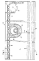
- the cord 13 is on a drop bar not shown in Fig. 1 at the lower end of the curtain 11 attached and in several places of the curtain guided by eyelets 14, whereby the curtain 11 when pulling up the cord 13 folds 16.
- the cord will be there wound on a winding drum 17, which in a housing 18th inserted freely rotatable and with this on the aluminum rail 12 is attached.
- the winding drum 17 is firmly connected to a gear 19, that protrudes into a longitudinal groove 20 in the rail 12 and engages with a pearl necklace 21 guided in this groove 20 stands.
- the pearl necklace 21 is designed as an endless chain and is guided along the entire length of the rail 12, so that with their help, several winding drums 17 parallel to each other are drivable.
- the pearl necklace 21 At the left end of the rail 12 is the pearl necklace 21 via a horizontally arranged deflection roller 22, the 2 can be seen more clearly, guided and in one second longitudinal groove in the rail 12 to the right end of the rail returned.
- At the right end of the rail 12 are two vertical deflection rollers 23 arranged parallel to one another and 24 arranged for the pearl necklace 21.
- the pearl necklace 21 hangs freely in a loop bottom so that by pulling on the front or rear loop end the winding drums either clockwise or counterclockwise driven and thus the roller blind 10 up or down can be moved.
- the curtain 11 of the blind 10 is there by means of a Velcro fastener 40 (FIG. 2) on the bar 12 attached.
- the aluminum rail 12 has three longitudinal grooves 20, 25 and 26 on.
- the longitudinal grooves 20 and 25 serve to guide the Pearl necklace 21.
- the groove 20 is U-shaped and after fully open at the bottom. The part of the pearl necklace led in it 21 engages the gear 19 of the winding drum 17 and stands therefore constantly under tension, so that threading out of the pearl necklace 21 from the groove 20 is impossible.
- the groove 25 is partially closed at the bottom to prevent it from falling out the pearl necklace 21 as the tension on the chain decreases 21 to prevent.
- the middle groove 26 serves the one hand Attachment of the winding drums and on the other hand the attachment the entire rail 12 on a ceiling or on beams or the like
- the groove 26 has locking projections 27 and 28, with the help of a snap connection between the winding drums 17 and the rail 12 are manufactured can.
- the housing 18 of the winding drum 17 has a 4 and 5 apparent elastic locking clips 29th on.
- the housing 18 also has a spur 30, which is also engages in the groove 26 of the strip 12 and a side Moving or twisting of the winding drum prevented.
- the Housing 18 of the winding drum 17 can also by a Screw attached to the rail 12 for displacement the winding drum in the longitudinal direction of the rail 12 at To prevent actuation of the pearl necklace 21.
- This screw can however, be a simple clamping screw so that it is not necessary holes in the rail for attaching the winding drum 17 to be provided. This is a simple and precise installation of the winding drums 17 on the rail 12 in Dependence on the arrangement of the cords 13 on the curtain 11 possible.
- the winding drum 17 is in one 5 visible U-shaped curved housing 18 mounted, whereby they are cut out on two also U-shaped Intermediate walls 33 and 34 are supported in the housing.
- On the gear 19 opposite end of the winding drum 17 is one Leaf spring 35 arranged, the winding drum semi-circular encloses and with their bent end regions 36 and 37 at a level in the housing which is not apparent from FIG. 4 18 supports.
- the leaf spring 35 thereby prevents the roller blind automatically due to the weight of the curtain unrolled. In this way, special locking devices for the pearl necklace 21 can be dispensed with.
- the winding drum 17 also does not have one with one from FIG. 4 apparent side locking groove provided opening 38 in, who fastens the end of the cord 13 with the aid of a locking clip can be. Together with the Velcro fastener shown in FIG. 2 40 between the rail 12 and the curtain 11 of the Roller blinds 10 is used for this easily detachable clip connection Strings to enable quick removal of the Roller blinds from the rail 12, for example around the curtain 11 clean or replace with another.
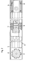
- the housing 60 shown in FIG. 6 corresponds in shape the housing 18 from FIGS. 4 and 5.
- the winding drum 41 supports again on intermediate walls 42 cut out in a U-shape and 43 in the housing 60. Outside their side walls 44 and 45, the winding drum each has a cylindrical one Extension 46 and 47, with a gear on the extension 47 48 is rotatably attached. On its top, the Extension 47 has an axially parallel recess 49.
- the extension 47 is on one cylindrical bearing journal 50 pushed on by means of a square projection 51 in a correspondingly shaped Opening 52 is mounted in the housing 40 against rotation.
- Coil spring 53 wound the ends 54 and 55 are bent radially outward and thereby an angular distance ⁇ to each other.
- the cylindrical extension 47 of the winding drum 41 is now placed on the journal 50 that the two spring ends 54 and 55 protrude into its recess 49 (Fig. 7).
- the rotatably attached to the extension 47 Gear 48 however, has a nose pointing radially inwards 57, which protrudes between the two spring ends 54 and 55 and can act on both.
- the gear 48 is, for example, a pearl necklace set in rotation
- the nose 57 presses from the inside according to the direction of rotation on one of the spring ends 54 or 55 and this widens the spring 53.
Abstract
Description
Die Erfindung betrifft ein Raffrollo nach dem Oberbegriff des
Anspruchs 1.The invention relates to a Roman blind according to the preamble of
Ein solches Raffrollo ist aus der EP-A-0 267 358 bereits bekannt. Die Antriebsschnur oder Perlkette der Wickeltrommeln dieses bekannten Rollos ist jedoch lediglich im Bereich von Antriebsrollen geführt. Dazwischen läuft die Schnur völlig frei unterhalb einer Schiene, an der die Gehäuse für die Antriebsrollen und Wickeltrommeln befestigt sind. Dieses Raffrollo läßt sich somit nicht in gebogener Form, beispielsweise zur Anordnung vor Fenstern in Erkern oder Eckbereichen, herstellen. Die Kette oder Schnur würde sich dann geradlinig von Rolle zu Rolle erstrecken und daher an der oder den in der Nähe des Scheitels des Bogens angeordneten Antriebsrollen scheuern oder gar aus diesen heraushüpfen.Such a Roman shade is already known from EP-A-0 267 358. The drive cord or pearl chain of the winding drums this known blind is only in the range of Drive rollers guided. In between, the cord runs completely freely below a rail on which the housing for the drive rollers and winding drums are attached. This Roman blind can not be in a curved form, for example to arrange in front of windows in bay windows or corner areas. The chain or cord would then straighten out Role to roll and therefore at the or in the Drive rollers located near the apex of the arc scrub or even hop out of them.
Aus der WO-A-92/09779 ist ein Rollo bekannt, dessen Zugschnüre mit einem Ende an einer Schiene befestigt und jeweils über zwei in der Schiene angeordnete Umlenkrollen geführt sind, wobei ein Raffen oder Absenken des Rollos durch Veränderung des gegenseitigen Abstandes der beiden Umlenkrollen erreicht wird. Hierzu ist jeweils eine der Umlenkrollen jedes Umlenkrollenpaares an einem gemeinsamen Gleitstück angeordnet, das mittels einer in der Schiene geführten Perlkette entlang der Schiene bewegbar ist. Wickeltrommeln zum Aufspulen der Zugschnüre sind hier nicht vorgesehen. Die überschüssige Zugschnurlänge beim Anheben des Behangs wird hier einfach in der Schiene zwischen den beiden Umlenkrollen gespannt. Eine bogenförmige Ausgestaltung dieses Rollos ist ebenfalls nicht möglich, da dann das Gleitstück in der Schiene nicht mehr bewegbar wäre und die Zugschnüre selbst an der Schiene scheuern oder sogar von den Umlenkrollen herunterhüpfen würden.From WO-A-92/09779 a roller blind is known, the pull cords fixed at one end to a rail and each over two deflection rollers arranged in the rail are guided, where the blind is raised or lowered by changing the mutual distance between the two pulleys becomes. For this purpose, one of the guide rollers of each pair of guide rollers is used arranged on a common slider that by means of a pearl chain in the rail along the Rail is movable. Winding drums for winding the pull cords are not provided here. The excess pull cord length when lifting the curtain, it is simply in the Rail tensioned between the two pulleys. An arcuate It is also not possible to design this roller blind, because then the slide in the rail can no longer be moved would be and rub the pull cords themselves on the rail or even jump off the pulleys.
Der vorliegenden Erfindung liegt die Aufgabe zugrunde, eine Herstellung von Raffrollos in Bogenform zu ermöglichen.The present invention has for its object a To enable the production of Roman blinds in the shape of an arch.
Die gestellte Aufgabe wird mit einem Raffrollo mit den Merkmalen
des Anspruchs 1 gelöst.The task is done with a Roman blind with the features
of
Bei dem erfindungsgemäßen Raffrollo kann die Leiste leicht gebogen werden, wobei die darauf angeordneten kleinen Wickeltrommeln nicht stören. Die Kette oder andere flexible Antriebsmittel werden beim Biegen einfach in den Nuten der Leiste mitgeführt. Die mindestens eine Wickeltrommel kann hierbei mit einem koaxial zu ihr angeordneten Zahnrad verbunden sein. Wenn die mindestens eine Wickeltrommel dabei in einem Gehäuse entgegen der Kraft einer Feder drehbar gelagert ist, läßt sich das selbsttätige Absenken des Rollos verhindern, ohne eine Arretierung für die Kette o. dgl. vorsehen zu müssen. Bei schwereren Behängen kann die Feder eine Schraubenfeder sein, die unter Spannung auf einem im Gehäuse verdrehsicher gelagerten zylindrischen Zapfen aufgewickelt ist, wobei die Federenden radial nach außen gebogen und in Umfangsrichtung der Feder um einen bestimmten Winkel voneinander beabstandet sind, die Wickeltrommel einen hohlzylindrischen Fortsatz mit einer achsparallel verlaufenden Aussparung aufweist, der drehbar auf dem zylindrischen Zapfen mit der Schraubenfeder derart aufgesteckt ist, daß die Federenden in die Aussparung hineinragen, und auf dem Außenumfang des Fortsatzes der Wickeltrommel ein Zahnrad drehbar angeordnet ist, das eine radial nach innen weisende Nase aufweist, die von außen in die Aussparung des Fortsatzes und zwischen die beiden Federenden hineinragt, so daß bei einer Drehung des Zahnrades jeweils eines der Federenden von der Nase beaufschlagt ist. Greift die Nase durch Betätigen des Zahnrades beispielsweise mittels einer Perlkette an einem der Federenden an, so wird diese aufgeweitet, d. h. ihre Windungen lösen sich vom Lagerzapfen und ermöglichen ein Drehen der Wickeltrommel und damit Hochziehen oder Absenken des Behangs. In the Roman shade according to the invention, the bar can easily are bent, with the small winding drums arranged on it do not bother. The chain or other flexible drive means are simply in the grooves of the bar when bending carried along. The at least one winding drum can do this be connected to a gear arranged coaxially to it. If the at least one winding drum is in a housing is rotatably supported against the force of a spring, can prevent the automatic lowering of the blind without one To have to provide locking for the chain or the like. At heavier curtains, the spring can be a coil spring, the live under tension on a stored in the housing against rotation cylindrical pin is wound, the spring ends bent radially outward and in the circumferential direction of the Spring are spaced apart by a certain angle, the winding drum has a hollow cylindrical extension with a has axially parallel recess that rotates the cylindrical pin plugged with the coil spring is that the spring ends protrude into the recess, and on the outer circumference of the extension of the winding drum Gear is rotatably arranged, one radially inward has pointing nose, which from the outside into the recess of the Extension and protrudes between the two spring ends, see above that when the gear rotates one of the spring ends is loaded by the nose. Grabs the nose by pressing the gear, for example by means of a pearl necklace one of the spring ends, it is widened, d. H. your Windings detach from the bearing journal and allow turning the winding drum and thus pulling up or lowering the Curtain.
Dreht sich jedoch die Wickeltrommel beispielsweise unter dem Gewicht eines schweren Behangs selbsttätig, so greift der hohlzylindrische Fortsatz der Wickeltrommel mit den Rändern seiner Aussparung von außen an einem der beiden Federenden an und drückt die Feder dadurch zusammen. Ihre Windungen legen sich fest um den Lagerzapfen und blockieren damit ein Weiterdrehen der Wickeltrommel. Bei leichteren Behängen können die Wickeltrommel und das Zahnrad aber auch aus einem Stück gefertigt sein, wobei ein selbsttätiges Entrollen des Behangs beispielsweise durch eine einfache Blattfeder verhindert werden kann, gegen deren Kraft die Wickeltrommel im Gehäuse gelagert ist.However, the winding drum rotates, for example, under the Weight of a heavy curtain automatically, so the hollow cylindrical extension of the winding drum with the edges its recess from the outside on one of the two spring ends and thereby compresses the spring. Lay your turns firmly around the trunnion and block further rotation the winding drum. With lighter curtains, the Winding drum and the gear but also made from one piece be, for example an automatic unrolling of the curtain can be prevented by a simple leaf spring can, against the force of which the winding drum is mounted in the housing is.
Die Leiste des Raffrollos kann vorteilhafterweise eine Profilschiene mit drei längsverlaufenden Nuten sein, wobei in den beiden äußeren Nuten die Kette oder der Zahnriemen o.dgl. geführt sind und die mittlere Nut der Befestigung der Wickeltrommeln sowie der Befestigung der Schiene selbst an der Decke oder an einem Träger dient. Eine solche Schiene ist preiswert herstellbar und ermöglicht eine exakte Führung der Kette o.dgl. in bezug auf die Wickeltrommeln. Die Gehäuse der Wikkeltrommeln können bei einer bevorzugten Ausführungsform mittels einer Clipsverbindung in der mittleren Nut der Profilschiene befestigbar sein. Dies hat gegenüber dem Vorsehen von separaten Befestigungsstellen - beispielsweise Bohrungen - für die Wickeltrommeln den Vorteil, daß keine Sonderanfertigungen von Schienen für Rollos verschiedener Breite notwendig sind. Die Schiene wird einfach als Langprofil hergestellt, von dem einzelne Schienen gewünschter Länge abgetrennt werden können. Die Trommeln werden anschließend entsprechend der Lage der Befestigungsstellen der Schnüre am Behang in die Schiene eingeclipst. Hierbei läßt sich die Lage der Wickeltrommeln so fein regulieren, daß ein exakter Eingriff der Antriebskette o.dgl. in die mit den Wickeltrommeln verbundenen Zahnräder gewährleistet ist. The strip of the Roman blind can advantageously be a profile rail be with three longitudinal grooves, wherein in the the outer grooves, the chain or the toothed belt or the like. are guided and the middle groove of the fastening of the winding drums and the fastening of the rail itself to the ceiling or serves on a carrier. Such a rail is inexpensive producible and enables exact chain guidance or the like in relation to the winding drums. The housing of the winding drums can in a preferred embodiment by means of a clip connection in the middle groove of the profile rail be attachable. This has to do with the provision of separate attachment points - for example holes - for the winding drums have the advantage that no custom-made products of rails for blinds of different widths are necessary. The rail is simply made as a long profile from which individual rails of the desired length can be separated. The drums are then placed according to the location of the Fastening points of the cords on the curtain clipped into the rail. Here, the position of the winding drums can be so regulate finely that an exact engagement of the drive chain or the like into the gears connected to the winding drums is guaranteed.
Die Leiste kann an einem ihrer Enden eine parallel zur Leistenebene ausgerichtete Umlenkrolle und an ihrem anderen Ende zwei senkrecht zur Leistenebene angeordnete Umlenkrollen für eine Perlkette zum Antrieb der Wickeltrommeln aufweisen. Die Perlkette ist hierbei als Endloskette ausgeführt und hängt über die beiden senkrechten Umlenkrollen der Leiste in einer losen Schlaufe nach unten, um ein Verstellen der Wickeltrommeln und damit der Lage des Behangs von Hand zu ermöglichen. Alternativ hierzu kann die Leiste an beiden Enden jeweils eine parallel zur Leistenebene ausgerichtete Umlenkrolle für eine Kette oder einen Zahnriemen o.dgl. aufweisen, wobei eine der Rollen von einem Motor antreibbar ist. Hier erfolgt der Antrieb ebenfalls wieder über ein Endlos-Antriebselement, das jedoch paßgenau um die beiden Umlenkrollen herumgeführt ist. Ein Motor an einer der Umlenkrollen sorgt für den Antrieb der Kette o.dgl. Zweckmäßigerweise kann dieser Motor mittels eines Schnellverschlusses an der Umlenkrolle befestigbar sein, um eine rasche Montage und Demontage zu ermöglichen.The strip can be parallel to the strip level at one of its ends aligned pulley and at its other end two deflection rollers arranged perpendicular to the last level have a pearl chain for driving the winding drums. The Pearl chain is designed as an endless chain and hangs over the two vertical pulleys of the bar in one loose loop down to adjust the winding drums and thus enable the position of the curtain by hand. Alternatively, the bar can have one at both ends Deflection roller aligned parallel to the last level Chain or a toothed belt or the like. have one of the Rollers can be driven by a motor. This is where the drive takes place again via an endless drive element, the however, is guided around the two guide rollers with a precise fit. A motor on one of the deflection rollers drives the Chain or the like This motor can expediently be operated by means of a Quick release on the pulley to be attachable to to enable quick assembly and disassembly.
Weitere Vorteile ergeben sich, wenn der Behang ebenfalls an der Leiste befestigt ist. Auf diese Weise ist das Raffrollo der Erfindung wesentlich platzsparender als die bislang bekannten Rollos, bei denen zusätzlich zur Antriebswelle für die Wickeltrommeln eine gesonderte Befestigungsleiste für den Behang des Rollos notwendig ist. Jetzt hingegen sind Wickeltrommeln, Behang und Antriebskette gemeinsam an einer einzigen Leiste befestigbar. Dadurch reduziert sich auch das Gewicht des Rollos, und es erhält ein filigraneres Aussehen. Der Behang kann dabei mittels eines Klettverschlusses lösbar an der Leiste befestigt sein. Außerdem kann das freie Ende der Wikkelschnur mittels eines Kunststoffclips lösbar an der Wickeltrommel befestigt sein. Auf diese Weise kann der Behang gemeinsam mit den Schnüren zum Reinigen oder zum Austausch gegen einen anderen Behang abgenommen werden. Further advantages arise when the curtain is also on the bar is attached. This is the roman blind the invention much more space-saving than the previously known Roller blinds, in addition to the drive shaft for the Winding drums a separate mounting strip for the Blinds are necessary. Now, however, are winding drums, Blind and drive chain together in one Bar attachable. This also reduces the weight of the blind, and it gets a more delicate look. The curtain can be detachably attached to the Bar be attached. In addition, the free end of the winding cord detachable on the winding drum by means of a plastic clip be attached. In this way, the curtain can be shared with the cords for cleaning or for exchange another curtain can be removed.
Nachfolgend wird ein bevorzugtes Ausführungsbeispiel eines erfindungsgemäßen Raffrollos anhand der Zeichnung näher erläutert.A preferred embodiment of a Roman blinds according to the invention explained in more detail with reference to the drawing.
Im einzelnen zeigen:
- Fig. 1
- eine Rückansicht, teilweise geschnitten, eines Raffrollos;
- Fig. 2
- eine Ansicht von oben auf das Raffrollo aus Fig. 1;
- Fig. 3
- einen Querschnitt durch die Schiene des Rollos nach Fig. 1;
- Fig. 4
- eine Ansicht von oben auf eine Wickeltrommel eines Raffrollos;
- Fig. 5
- eine Seitenansicht der Wickeltrommel nach Fig. 4;
- Fig. 6
- eine der Fig. 4 entsprechende Ansicht von oben auf eine zweite Ausführungsform einer Wickeltrommel mit Gehäuse;
- Fig. 7
- eine Ansicht von vorn auf eine Wickeltrommel nach Fig. 6 ohne Gehäuse;
- Fig. 8
- Detailansicht eines Lagerzapfens mit Schraubenfeder der Wickeltrommel nach Fig. 6;
- Fig. 9
- eine Draufsicht auf den Lagerzapfen mit Schraubenfeder nach Fig. 8.
- Fig. 1
- a rear view, partly in section, of a Roman blind;
- Fig. 2
- a top view of the Roman shade from Fig. 1;
- Fig. 3
- a cross section through the rail of the blind according to Fig. 1;
- Fig. 4
- a view from above of a winding drum of a Roman shade;
- Fig. 5
- a side view of the winding drum of FIG. 4;
- Fig. 6
- 4 a view from above corresponding to a second embodiment of a winding drum with housing;
- Fig. 7
- a front view of a winding drum of Figure 6 without the housing.
- Fig. 8
- Detailed view of a journal with coil spring of the winding drum according to Fig. 6;
- Fig. 9
- a plan view of the bearing pin with coil spring according to FIG. 8.
Das Raffrollo 10 nach Fig. 1 besteht aus einem Behang 11, der
an einer Aluminiumschiene 12 befestigt ist und mittels einer
oder bei entsprechender Länge des Rollos auch mehrerer Schnüre
13 in der Höhe verstellbar ist. Die Schnur 13 ist hierzu an
einem in Fig. 1 nicht dargestellten Fallstab am unteren Ende
des Behangs 11 befestigt und an mehreren Stellen des Behangs
durch ösen 14 geführt, wodurch sich der Behang 11 beim Hochziehen
der Schnur 13 in Falten 16 legt. Die Schnur wird dabei
auf eine Wickeltrommel 17 aufgespult, die in ein Gehäuse 18
frei drehbar eingesetzt und mit diesem an der Aluminiumschiene
12 befestigt ist.1 consists of a
Die Wickeltrommel 17 ist fest mit einem Zahnrad 19 verbunden,
das in eine Längsnut 20 in der Schiene 12 hineinragt und
mit einer in dieser Nut 20 geführten Perlkette 21 in Eingriff
steht. Die Perlkette 21 ist als Endloskette ausgeführt und
wird entlang der gesamten Länge der Schiene 12 geführt, so daß
mit ihrer Hilfe mehrere Wickeltrommeln 17 parallel zueinander
antreibbar sind. Am linken Ende der Schiene 12 wird die Perlkette
21 über eine horizontal angeordnete Umlenkrolle 22, die
aus Fig. 2 deutlicher ersichtlich ist, geführt und in einer
zweiten Längsnut in der Schiene 12 zum rechten Ende der Schiene
zurückgeführt. Am rechten Ende der Schiene 12 sind zwei
senkrechte und parallel zueinander angeordnete Umlenkrollen 23
und 24 für die Perlkette 21 angeordnet. Von diesen Rollen 23
und 24 hängt die Perlkette 21 in einer Schlaufe frei nach
unten, so daß durch Ziehen am vorderen oder hinteren Schlaufenende
die Wickeltrommeln entweder im oder entgegen dem Uhrzeigersinn
angetrieben und damit das Rollo 10 auf oder ab
bewegt werden kann. Der Behang 11 des Rollos 10 ist dabei
mittels eines Klettverschlusses 40 (Fig. 2) an der Leiste 12
befestigt.The winding
In Fig. 3 ist ein Querschnitt durch die Schiene 12 dargestellt.
Die Aluminiumschiene 12 weist drei Längsnuten 20, 25
und 26 auf. Die Längsnuten 20 und 25 dienen der Führung der
Perlkette 21. Die Nut 20 ist U-förmig ausgebildet und nach
unten vollständig offen. Der in ihr geführte Teil der Perlkette
21 greift am Zahnrad 19 der Wickeltrommel 17 an und steht
daher ständig unter Spannung, so daß ein Ausfädeln der Perlkette
21 aus der Nut 20 unmöglich ist. Im Gegensatz dazu ist
die Nut 25 nach unten hin teilweise verschlossen, um ein Herausfallen
der Perlkette 21 bei nachlassendem Zug auf der Kette
21 zu verhindern. Die mittlere Nut 26 dient einerseits der
Befestigung der Wickeltrommeln und andererseits der Befestigung
der gesamten Schiene 12 an einer Decke oder an Trägern
o.dgl. An ihrem unteren Ende weist die Nut 26 Rastvorsprünge
27 und 28 auf, mit deren Hilfe eine Rastverbindung zwischen
den Wickeltrommeln 17 und der Schiene 12 hergestellt werden
kann. Hierzu weist das Gehäuse 18 der Wickeltrommel 17 einen
aus den Fig. 4 und 5 ersichtlichen elastischen Rastclips 29
auf. Das Gehäuse 18 weist zudem einen Sporn 30 auf, der ebenfalls
in die Nut 26 der Leiste 12 eingreift und ein seitliches
Verschieben oder Verdrehen der Wickeltrommel verhindert. Das
Gehäuse 18 der Wickeltrommel 17 kann zudem noch durch eine
Schraube an der Schiene 12 befestigt werden, um eine Verschiebung
der Wickeltrommel in Längsrichtung der Schiene 12 beim
Betätigen der Perlkette 21 zu verhindern. Diese Schraube kann
jedoch eine einfache Klemmschraube sein, so daß es nicht notwendig
ist, in der Schiene Bohrungen zum Anbringen der Wickeltrommel
17 vorzusehen. Auf diese Weise ist eine einfache und
lagegenaue Montage der Wickeltrommeln 17 an der Schiene 12 in
Abhängigkeit von der Anordnung der Schnüre 13 am Behang 11
möglich.3 shows a cross section through the
Aus Fig. 4 ist die einstückige Ausbildung der Wickeltrommel 17
mit ihren beiden Seitenwandungen 31 und 32 sowie dem Zahnrad
19 ersichtlich. Die Wickeltrommel 17 ist dabei in einem aus
Fig. 5 ersichtlichen U-förmig gebogenen Gehäuse 18 gelagert,
wobei sie sich auf zwei ebenfalls U-förmig ausgeschnittene
Zwischenwandungen 33 und 34 im Gehäuse abstützt. An dem Zahnrad
19 gegenüberliegenden Ende der Wickeltrommel 17 ist eine
Blattfeder 35 angeordnet, die die Wickeltrommel halbkreisförmig
umschließt und mit ihren abgebogenen Endbereichen 36 und
37 auf einer aus Fig. 4 nicht ersichtlichen Stufe im Gehäuse
18 abstützt. Bei Drehung der Wickeltrommel 17 wird jeweils
einer der Endbereiche 36, 37 der Blattfeder 35 gegen die Stufe
des Gehäuses gedrückt, wodurch ein Gegendruck von der Feder 35
auf die Wickeltrommel 17 ausgeübt wird und diese in ihrer
Bewegung bremst. Die Blattfeder 35 verhindert dadurch, daß
sich das Rollo durch das Gewicht des Behanges selbsttätig
entrollt. Auf diese Weise kann auf besondere Arretierungsvorrichtungen
für die Perlkette 21 verzichtet werden. Die Wickeltrommel
17 weist außerdem eine mit einer aus Fig. 4 nicht
ersichtlichen seitlichen Rastnut versehene Öffnung 38 auf, in
der das Ende der Schnur 13 mit Hilfe eines Rastclips befestigt
werden kann. Gemeinsam mit dem aus Fig. 2 ersichtlichen Klettverschluß
40 zwischen der Schiene 12 und dem Behang 11 des
Rollos 10 dient diese einfach lösbare Clipsverbindung des
Schnurendes der Ermöglichung einer schnellen Entnahme des
Rollos von der Schiene 12, beispielsweise um den Behang 11 zu
reinigen oder gegen einen anderen auszutauschen.4 is the one-piece design of the winding drum 17th
with its two
Bei Rollos mit sehr schweren Behängen kann eine Lagerung der Wickeltrommel gemäß den Fig. 6 bis 9 vorgenommen werden.In the case of blinds with very heavy curtains, storage of the Winding drum can be made according to FIGS. 6 to 9.
Das in Fig. 6 gezeigte Gehäuse 60 entspricht in seiner Form
dem Gehäuse 18 aus Fig. 4 und 5. Die Wickeltrommel 41 stützt
sich wieder auf U-förmig ausgeschnittene Zwischenwandungen 42
und 43 im Gehäuse 60 ab. Außerhalb ihrer Seitenwandungen 44
und 45 weist die Wickeltrommel jeweils einen zylindrischen
Fortsatz 46 und 47 auf, wobei auf den Fortsatz 47 ein Zahnrad
48 drehbar aufgesetzt ist. Auf seiner Oberseite weist der
Fortsatz 47 eine achsparallel verlaufende Aussparung 49 auf.The
Wie aus Fig. 7 ersichtlich, ist der Fortsatz 47 auf einen
zylindrischen Lagerzapfen 50 aufgeschoben, der mittels eines
vierkantigen Vorsprungs 51 in einer entsprechend geformten
Öffnung 52 im Gehäuse 40 verdrehsicher gelagert ist. Um den
Lagerzapfen 50 ist eine aus den Fig. 8 und 9 deutlicher ersichtliche
Schraubenfeder 53 gewickelt, deren Enden 54 und 55
radial nach außen gebogen sind und dabei einen Winkelabstand α
zueinander aufweisen. Der zylindrische Fortsatz 47 der Wickeltrommel
41 ist nun so auf den Lagerzapfen 50 aufgesetzt, daß
die beiden Federenden 54 und 55 in seine Aussparung 49 hineinragen
(Fig. 7). Das auf den Fortsatz 47 drehbar aufgesteckte
Zahnrad 48 hingegen weist eine radial nach innen weisende Nase
57 auf, die zwischen die beiden Federenden 54 und 55 hineinragt
und beide beaufschlagen kann.As can be seen from FIG. 7, the
Versucht sich nun die Wickeltrommel 41 z.B. aufgrund des Gewichts
des Behanges selbstätig zu drehen, so drückt je nach
Drehrichtung eine der beiden Innenkanten 58 oder 59 der Aussparung
49 des Fortsatzes 47 der Wickeltrommel 41 von außen
gegen eines der beiden Federenden 54 oder 55 und drückt dadurch
die Schraubenfeder 53 zusammen. Ihre Windungen 56 legen
sich fest um den Lagerzapfen 50 und verhindern somit ein Weiterdrehen
der Wickeltrommel 41 und damit ein selbsttätiges
Absenken des Rollos.Now tries the winding
Wird hingegen das Zahnrad 48 beispielsweise über eine Perlenkette
in Drehung versetzt, so drückt die Nase 57 von innen je
nach Drehrichtung auf eines der Federenden 54 oder 55 und
weitet die Feder 53 dadurch auf.If, on the other hand, the
Ihre Windungen 56 lösen sich vom Lagerzapfen 50 und ermöglichen
ein Drehen der Gesamtanordnung bestehend aus Zahnrad 48,
Wickeltrommel 41 und Schraubenfeder 53 auf dem Lagerzapfen 50.
Das Rollo kann nun leicht entweder hochgezogen oder abgesenkt
werden.Their turns 56 detach from the
Claims (13)
- Roman blind with at least one winding drum (17) onto which is coiled a string (13) which is attached to the drape or tape for gathering and lowering the drape (11), and the at least one winding drum (17) is rotationally mounted on a strip (12) which extends parallel to the drape (11), characterised in that the winding drum (17) is driven by a chain (21) or toothed belt or the like which is guided along the flexible strip (12) in grooves (20, 25).
- Roman blind according to Claim 1, characterised in that the at least one winding drum (17) is linked to a toothed wheel (19) which is arranged coaxially to the latter.
- Roman blind according to Claim 1 or 2, characterised in that the at least one winding drum (17) is mounted in a housing (18) so as to be rotary against the load of a spring (35).
- Roman blind according to Claim 3, characterised in that the spring is a helical spring (53) which is wound under tension onto a cylindrical pin (50) which is non-rotationally mounted in the housing, and the spring ends (54, 55) are bent radially outwards and spaced in the peripheral direction of spring (53) at a specified angle (α), the winding drum (41) comprises a hollow-cylindrical extension (47) with an axis-parallel extending cutout (49), which is rotationally pushed onto the cylindrical pin (50) with the helical spring (53) in such a manner that the spring ends (54, 55) protrude into the cutouts (49), and on the outer periphery of the extension (47) of the winding drum (41) is rotationally arranged a toothed wheel (48) having a radially inwardly oriented nose (57) which protrudes from the outside into the cutout (49) of the extension (47) and between the two spring ends (54, 55), so that during a rotation of the toothed wheel (48) one of the spring ends (54, 55) is loaded by the nose (57).
- Roman blind according to Claim 2 or 3, characterised in that the winding drum (17) and the toothed wheel (19) are made in one piece.
- Roman blind according to one of Claims 1 to 5, characterised in that the strip is a profile track (12) with three longitudinally extending grooves (20, 25, 26), and in the two outer grooves (20, 25) is guided the chain (21) or the toothed belt or the like, and the central groove (26) serves to mount the winding drums (17) as well as to mount the track (12) to a ceiling or a support.
- Roman blind according to Claim 6, characterised in that the housing (18) of the winding drums (17) is mountable by means of a clip connection (27, 28; 29) in the central groove (26) of the profile track (12).
- Roman blind according to one of Claims 1 to 7, characterised in that the strip (12) has at one of its ends a diverting roller (22), which is oriented parallel to the strip plane, and at its other end two diverting rollers, which are arranged vertically to the strip plane, for a pearl chain (21) to drive the winding drums (17).
- Roman blind according to one of Claims 1 to 7, characterised in that the strip (12) has on both ends a respective diverting roller (22), which is aligned parallel to the strip plane, for a chain (21) or a toothed belt or the like, and one of the rollers is driven by a motor.
- Roman blind according to Claim 9, characterised in that the motor is mountable to the diverting roller by means of an instantaneous coupling.
- Roman blind according to one of Claims 1 to 10, characterised in that the drape (11) is also attached to the strip (12).
- Roman blind according to Claim 11, characterised in that the drape (11) is releasably attached to the strip (12) by means of a barbed wire closure.
- Roman blind according to one of Claims 1 to 12, characterised in that one end of the winding cord (13) is releasably attached to the winding drum (17) by means of a plastic clip.
Applications Claiming Priority (4)
| Application Number | Priority Date | Filing Date | Title |
|---|---|---|---|
| DE4223507 | 1992-07-17 | ||
| DE4223507 | 1992-07-17 | ||
| DE4244334 | 1992-12-28 | ||
| DE4244334A DE4244334C2 (en) | 1992-07-17 | 1992-12-28 | Raff curtain |
Publications (2)
| Publication Number | Publication Date |
|---|---|
| EP0581005A1 EP0581005A1 (en) | 1994-02-02 |
| EP0581005B1 true EP0581005B1 (en) | 1998-12-16 |
Family
ID=25916674
Family Applications (1)
| Application Number | Title | Priority Date | Filing Date |
|---|---|---|---|
| EP93109579A Expired - Lifetime EP0581005B1 (en) | 1992-07-17 | 1993-06-16 | Roman shade |
Country Status (2)
| Country | Link |
|---|---|
| EP (1) | EP0581005B1 (en) |
| AT (1) | ATE174656T1 (en) |
Families Citing this family (1)
| Publication number | Priority date | Publication date | Assignee | Title |
|---|---|---|---|---|
| CN114934428B (en) * | 2022-05-09 | 2023-08-22 | 田晓明 | Concrete pavement maintenance device |
Citations (1)
| Publication number | Priority date | Publication date | Assignee | Title |
|---|---|---|---|---|
| WO1992009779A1 (en) * | 1990-11-23 | 1992-06-11 | Ctv S.R.L. | Device for working vertically-operated window curtains with multiplied travel |
Family Cites Families (3)
| Publication number | Priority date | Publication date | Assignee | Title |
|---|---|---|---|---|
| IT8421810V0 (en) * | 1984-05-15 | 1984-05-15 | Arquati Spa | DRIVE DEVICE, PARTICULARLY DESIGNED FOR PACKAGE OR PANEL CURTAINS. |
| DE3634547A1 (en) * | 1986-10-10 | 1988-04-14 | Dieter Rometsch | REEL CURTAIN SYSTEM |
| DE3800631A1 (en) * | 1987-12-15 | 1989-06-29 | Bratschi Silent Gliss | GATHERING CURTAIN |
-
1993
- 1993-06-16 AT AT93109579T patent/ATE174656T1/en not_active IP Right Cessation
- 1993-06-16 EP EP93109579A patent/EP0581005B1/en not_active Expired - Lifetime
Patent Citations (1)
| Publication number | Priority date | Publication date | Assignee | Title |
|---|---|---|---|---|
| WO1992009779A1 (en) * | 1990-11-23 | 1992-06-11 | Ctv S.R.L. | Device for working vertically-operated window curtains with multiplied travel |
Also Published As
| Publication number | Publication date |
|---|---|
| ATE174656T1 (en) | 1999-01-15 |
| EP0581005A1 (en) | 1994-02-02 |
Similar Documents
| Publication | Publication Date | Title |
|---|---|---|
| DE69831098T2 (en) | FLAT SPRING AND WINDOW COVER | |
| DE602004012523T2 (en) | Rouleaux for light intensity adjustment | |
| EP0861040B1 (en) | Curtain, in particular a curtain to be gathered | |
| EP0372004B1 (en) | Tableau curtain | |
| DE3037701A1 (en) | SHUTTERS, SHUTTERS OR THE LIKE | |
| AT399370B (en) | LOUVRE | |
| DE3345503A1 (en) | Roller blind for vehicle windows | |
| DE3037759A1 (en) | REEL SLAT STORE | |
| AT394880B (en) | REEL SLAT STORE | |
| DE4034614C3 (en) | Device for shading window areas | |
| EP0860579B1 (en) | Roller shutter tassel drive | |
| EP0267358A1 (en) | Take-up device for raising and lowering a take-up curtain | |
| EP0581005B1 (en) | Roman shade | |
| CH650311A5 (en) | REEL SLAT STORE. | |
| DE4244334C2 (en) | Raff curtain | |
| DE102007011267B4 (en) | Apparatus for shirring a curtain with Einzelzugschnüren | |
| DE3037703A1 (en) | Venetian blinds with guide elements arranged at the ends of the slats | |
| DE19534970C2 (en) | Turning device for a venetian blind | |
| DE10236869A1 (en) | Gathered blind has winding rollers for draw cords and turning rollers for adjusting incline and with inclined flanks above coupling band guide which diverts ends of coupling bands into desired plane | |
| EP1840319A2 (en) | Coiling device of a roller blind | |
| EP0618340B1 (en) | Drive mechanism for slat blind, particularly for roof windows | |
| CH653095A5 (en) | Gatherable lamellar blind with an arrangement for approximately horizontal alignment of the lowest lamella | |
| DE2400643A1 (en) | Winder mechanism for venetian blind - has cord-holder joined to attachment pivot-connected to coil spring | |
| EP1842464B1 (en) | Device for gathering a gathered curtain with individual cords | |
| DE3901994C2 (en) |
Legal Events
| Date | Code | Title | Description |
|---|---|---|---|
| PUAI | Public reference made under article 153(3) epc to a published international application that has entered the european phase |
Free format text: ORIGINAL CODE: 0009012 |
|
| AK | Designated contracting states |
Kind code of ref document: A1 Designated state(s): AT BE CH FR GB IT LI NL |
|
| 17P | Request for examination filed |
Effective date: 19940104 |
|
| 17Q | First examination report despatched |
Effective date: 19951214 |
|
| GRAG | Despatch of communication of intention to grant |
Free format text: ORIGINAL CODE: EPIDOS AGRA |
|
| GRAG | Despatch of communication of intention to grant |
Free format text: ORIGINAL CODE: EPIDOS AGRA |
|
| GRAH | Despatch of communication of intention to grant a patent |
Free format text: ORIGINAL CODE: EPIDOS IGRA |
|
| GRAH | Despatch of communication of intention to grant a patent |
Free format text: ORIGINAL CODE: EPIDOS IGRA |
|
| GRAA | (expected) grant |
Free format text: ORIGINAL CODE: 0009210 |
|
| AK | Designated contracting states |
Kind code of ref document: B1 Designated state(s): AT BE CH FR GB IT LI NL |
|
| REF | Corresponds to: |
Ref document number: 174656 Country of ref document: AT Date of ref document: 19990115 Kind code of ref document: T |
|
| REG | Reference to a national code |
Ref country code: CH Ref legal event code: NV Representative=s name: ROTTMANN, ZIMMERMANN + PARTNER AG Ref country code: CH Ref legal event code: EP |
|
| ITF | It: translation for a ep patent filed |
Owner name: STUDIO APRA' BREVETTI |
|
| GBT | Gb: translation of ep patent filed (gb section 77(6)(a)/1977) |
Effective date: 19990204 |
|
| ET | Fr: translation filed | ||
| PLBE | No opposition filed within time limit |
Free format text: ORIGINAL CODE: 0009261 |
|
| STAA | Information on the status of an ep patent application or granted ep patent |
Free format text: STATUS: NO OPPOSITION FILED WITHIN TIME LIMIT |
|
| 26N | No opposition filed | ||
| REG | Reference to a national code |
Ref country code: GB Ref legal event code: IF02 |
|
| PGFP | Annual fee paid to national office [announced via postgrant information from national office to epo] |
Ref country code: BE Payment date: 20030425 Year of fee payment: 11 |
|
| PGFP | Annual fee paid to national office [announced via postgrant information from national office to epo] |
Ref country code: CH Payment date: 20030428 Year of fee payment: 11 |
|
| PGFP | Annual fee paid to national office [announced via postgrant information from national office to epo] |
Ref country code: FR Payment date: 20030507 Year of fee payment: 11 |
|
| PGFP | Annual fee paid to national office [announced via postgrant information from national office to epo] |
Ref country code: GB Payment date: 20030606 Year of fee payment: 11 |
|
| PGFP | Annual fee paid to national office [announced via postgrant information from national office to epo] |
Ref country code: AT Payment date: 20030626 Year of fee payment: 11 |
|
| PGFP | Annual fee paid to national office [announced via postgrant information from national office to epo] |
Ref country code: NL Payment date: 20030630 Year of fee payment: 11 |
|
| PG25 | Lapsed in a contracting state [announced via postgrant information from national office to epo] |
Ref country code: GB Free format text: LAPSE BECAUSE OF NON-PAYMENT OF DUE FEES Effective date: 20040616 Ref country code: AT Free format text: LAPSE BECAUSE OF NON-PAYMENT OF DUE FEES Effective date: 20040616 |
|
| PG25 | Lapsed in a contracting state [announced via postgrant information from national office to epo] |
Ref country code: LI Free format text: LAPSE BECAUSE OF NON-PAYMENT OF DUE FEES Effective date: 20040630 Ref country code: CH Free format text: LAPSE BECAUSE OF NON-PAYMENT OF DUE FEES Effective date: 20040630 Ref country code: BE Free format text: LAPSE BECAUSE OF NON-PAYMENT OF DUE FEES Effective date: 20040630 |
|
| BERE | Be: lapsed |
Owner name: *MHZ HACHTEL G.M.B.H. & CO. K.G. Effective date: 20040630 |
|
| PG25 | Lapsed in a contracting state [announced via postgrant information from national office to epo] |
Ref country code: NL Free format text: LAPSE BECAUSE OF NON-PAYMENT OF DUE FEES Effective date: 20050101 |
|
| GBPC | Gb: european patent ceased through non-payment of renewal fee |
Effective date: 20040616 |
|
| REG | Reference to a national code |
Ref country code: CH Ref legal event code: PL |
|
| PG25 | Lapsed in a contracting state [announced via postgrant information from national office to epo] |
Ref country code: FR Free format text: LAPSE BECAUSE OF NON-PAYMENT OF DUE FEES Effective date: 20050228 |
|
| NLV4 | Nl: lapsed or anulled due to non-payment of the annual fee |
Effective date: 20050101 |
|
| REG | Reference to a national code |
Ref country code: FR Ref legal event code: ST |
|
| PG25 | Lapsed in a contracting state [announced via postgrant information from national office to epo] |
Ref country code: IT Free format text: LAPSE BECAUSE OF NON-PAYMENT OF DUE FEES Effective date: 20050616 |