EP0580705B1 - Zerstäuber - Google Patents
Zerstäuber Download PDFInfo
- Publication number
- EP0580705B1 EP0580705B1 EP92909202A EP92909202A EP0580705B1 EP 0580705 B1 EP0580705 B1 EP 0580705B1 EP 92909202 A EP92909202 A EP 92909202A EP 92909202 A EP92909202 A EP 92909202A EP 0580705 B1 EP0580705 B1 EP 0580705B1
- Authority
- EP
- European Patent Office
- Prior art keywords
- spray
- nozzle
- shroud
- liquid
- heated gas
- Prior art date
- Legal status (The legal status is an assumption and is not a legal conclusion. Google has not performed a legal analysis and makes no representation as to the accuracy of the status listed.)
- Expired - Lifetime
Links
Images

Classifications
-
- B—PERFORMING OPERATIONS; TRANSPORTING
- B05—SPRAYING OR ATOMISING IN GENERAL; APPLYING FLUENT MATERIALS TO SURFACES, IN GENERAL
- B05B—SPRAYING APPARATUS; ATOMISING APPARATUS; NOZZLES
- B05B7/00—Spraying apparatus for discharge of liquids or other fluent materials from two or more sources, e.g. of liquid and air, of powder and gas
- B05B7/16—Spraying apparatus for discharge of liquids or other fluent materials from two or more sources, e.g. of liquid and air, of powder and gas incorporating means for heating or cooling the material to be sprayed
- B05B7/20—Spraying apparatus for discharge of liquids or other fluent materials from two or more sources, e.g. of liquid and air, of powder and gas incorporating means for heating or cooling the material to be sprayed by flame or combustion
-
- B—PERFORMING OPERATIONS; TRANSPORTING
- B05—SPRAYING OR ATOMISING IN GENERAL; APPLYING FLUENT MATERIALS TO SURFACES, IN GENERAL
- B05B—SPRAYING APPARATUS; ATOMISING APPARATUS; NOZZLES
- B05B7/00—Spraying apparatus for discharge of liquids or other fluent materials from two or more sources, e.g. of liquid and air, of powder and gas
- B05B7/02—Spray pistols; Apparatus for discharge
- B05B7/08—Spray pistols; Apparatus for discharge with separate outlet orifices, e.g. to form parallel jets, i.e. the axis of the jets being parallel, to form intersecting jets, i.e. the axis of the jets converging but not necessarily intersecting at a point
- B05B7/0807—Spray pistols; Apparatus for discharge with separate outlet orifices, e.g. to form parallel jets, i.e. the axis of the jets being parallel, to form intersecting jets, i.e. the axis of the jets converging but not necessarily intersecting at a point to form intersecting jets
Definitions
- This invention relates to liquid spray devices of the kind wherein liquid is discharged in the form of a thin sheet which subsequently breaks down to form droplets.
- the sheet has the shape of a hollow cone.
- the liquid spray devices of this invention find particular application in agricultural or horticultural spraying apparatus and in coating apparatus such as is used for paint application. Regulation of the droplet size is important, particularly to minimise wastage of expensive agrochemicals or other materials. Small drops which can be lost as mist or large drops which fall to the ground are uneconomical and may create toxicity problems. Elimination of spray drift is especially important.
- GB-A-1561642 discloses a liquid spray device wherein hot gas from a methane burner is led to the vicinity of the orifice of a conical sprayer nozzle.
- the present invention relates to an improvement on the prior disclosure which enables the invention to be put into practice effectively. Several improvements are also realised.
- a liquid spray device includes a nozzle adapted to form a conical sheet of liquid which disintegrates downstream of the nozzle to form a spray, a source of heated gas and a shroud adapted to protect said gas in the vicinity of the nozzle from draughts the source being located so that the gas stream is directed onto the spray at a region wherein the sheet disintegrates to form droplets.
- the gas stream impinges directly on said region of the liquid so that heated gas is drawn through the conical liquid curtain so that the gas contacts the interior surface of it at the point of initiation of the break-up into droplets or immediately upstream of that point.
- the heated gas stream is preferably provided by combustion of gaseous fuel, although liquid fuel burners may be employed. While electrically heated gas streams are not excluded, use of combustion gas is more efficient and practically convenient.
- the droplet size distribution is enhanced by reduction in the number of undersized droplets.
- the apical angle of a conical spray is increased, enhancing the coverage achieved by the spray and allowing reduction in hydrostatic pressure.
- the shroud encloses the nozzle and has inlets through which air can be drawn by the spray, and an outlet for the spray and entrained air.
- the shroud is preferably arranged to enclose a toroidal body of gas to maintain the heated gas stream in contact with the break-up region of the sprayed liquid.
- the shroud also serves to protect the emergent spray from wind and other external influences.
- the shroud provides a jet pump to entrain ambient air and equalise pressure in the burner tube. This also serves to cool the burner tube. This may take the form of an open ended tube surrounding the burner jet at which fuel gas combustion occurs. The periphery of the shroud adjacent the outlet for the spray is preferably perpendicular to the latter. This serves to reduce turbulence within the shroud.
- a thermal sensor may be located on the shroud on the opposite side to the inlet for heated gas.
- the sensor may be arranged to interrupt the fuel supply to the flame or other supply of heated gas if the spray is interrupted. This serves to prevent damage to the spray nozzle and shroud in the event that the cooling liquid spray is interrupted. In addition pyrolysis or oxidation of agrochemicals, which can lead to toxic products is avoided. This allows the nozzle and shroud to be fabricated from plastics or another heat sensitive material.
- the burner unit is preferably arranged so that the inlet for heated gas is perpendicular to the axis of a conical spray, for example horizontal, radially to the axis of the conical spray in a downwardly directed agricultural sprayer.
- a shroud may afford a secondary jet pump due to the passage of the body of liquid through it. This allows control of the mass density of the ionised species within the gas stream to optimise efficient droplet formation. This effect is enhanced by the perpendicular edge of the shroud and the proximity of the edge of the shroud to the conical body of liquid emergent from the apparatus.
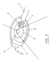
- the sprayer shown in cross-section in Figure 1 comprises a conventional plastics spray nozzle 1 having an inlet swirl chamber and outlet which generates a conical sheet of liquid 2.
- Barrel 4 is open-ended at 5 to create a jet pump to accelerate heated gas from the flame 9 towards the sprayed liquid 2.
- the heated gas 9 impinges radially on the conical body of liquid 2 at the axial distance from the nozzle orifice shown by the arrow 10 where the sheet 2 breaks into droplets.
- Action of the heated gas 9 on the jet 2 causes the position of the break- up zone 10 to move upstream from the position if no heated gas is applied.
- the barrel 3 is located at a distance from the nozzle 1 at which a steady state is achieved in use of the apparatus.
- a toroidal shroud 7 having inlets 8 and an outlet 12 surrounds the spray to retain the heated gas in contact with the break-up zone 10. This may be conveniently achieved by arranging the inlet 8 so that air flows within the toroidal shroud to retain heated air adjacent the breakup zone 10.
- the Bernouilli effect causes a reduction of pressure within the cone 11 drawing heated gas through the liquid curtain 2. Promotion of the rupture of the liquid sheet 2 by ionised or other particles in the heated gas stream is enhanced by contact of the heated gas with the interior of the sheet as shown at 11.
- the apical angle of the emergent spray (a) is increased and the number of small droplets which form mist is reduced, reducing the losses from the spray.
- the thickness (b) of the annular ring of droplets in the spray curtain is reduced.
- Proximity of the periphery of the shroud 12 to the spray leaving the apparatus reduces the effect of draughts. Entrainment of air entering through the holes 8 in the body of sprayed liquid creates a jet pump effect drawing air into the interior of the shroud 7 to control the atmosphere within it.
- a heat sensor 13 located upon a support 14 is disposed behind an aperture 15 in the shroud opposite to the burner 3. Interruption of the liquid flow causes the flame 9 to contact the sensor 13 to actuate the regulator 6 and cut off the gas flow. Damage to the nozzle 1 and shroud by the presence of a flame is avoided.
Landscapes
- Chemical & Material Sciences (AREA)
- Engineering & Computer Science (AREA)
- Combustion & Propulsion (AREA)
- Nozzles (AREA)
Claims (7)
- Flüssigkeits-Zerstäuber, mit einer Düse (1), die so ausgebildet ist, daß sie einen konischen Flüssigkeits-Film bildet, welcher sich stromab der Düse zur Bildung eines Sprühnebels auflöst, einer Quelle (3) für erhitztes Gas (9) und einer Abschirmung (7), welche zum Schützen des Gases nahe der Düse (1) vor Luftzug ausgebildet ist,
dadurch gekennzeichnet,
daß die Quelle (3) derart angeordnet ist, daß der Gasstrom (9) in einem Bereich (10) auf den Sprühnebel gerichtet ist, wo sich der Sprühnebel unter Bildung von Tröpfchen auflöst. - Zerstäuber nach Anspruch 1, bei dem erhitztes Gas während des Betriebs durch den Flüssigkeits-Film (2) angesogen wird und mit dessen innerer Oberfläche kontaktiert.
- Zerstäuber nach einem der vorhergehenden Ansprüche, bei dem das erhitzte Gas durch Verbrennung eines gasförmigen oder flüssigen Brennstoffes bereitgestellt ist.
- Zerstäuber nach einem der vorhergehenden Ansprüche, bei dem die Abschirmung (7) die Düse (1) umschließt und einen Einlaß (8) für Luft und einen Auslaß (12) für den Sprühnebel und mitgerissene Luft enthält.
- Zerstäuber nach Anspruch 4, bei dem während des Betriebs der Umfang der an den Auslaß angrenzenden Abschirmung (7) senkrecht zu dem Sprühnebel angeordnet ist.
- Zerstäuber nach einem der vorhergenden Ansprüche, bei dem ein Temperatursensor (13) an der Abschirmung (7) gegenüber dem Einlaß für erhitztes Gas angeordnet ist,
- Zerstäuber nach einem der vorhergehenden Ansprüche, bei dem der Einlaß für erhitztes Gas senkrecht zu der Achse des konischen Sprühnebels ist,
Applications Claiming Priority (3)
| Application Number | Priority Date | Filing Date | Title |
|---|---|---|---|
| GB91088658 | 1991-04-25 | ||
| GB919108865A GB9108865D0 (en) | 1991-04-25 | 1991-04-25 | Sprayer |
| PCT/GB1992/000757 WO1992019385A1 (en) | 1991-04-25 | 1992-04-24 | Sprayer |
Publications (2)
| Publication Number | Publication Date |
|---|---|
| EP0580705A1 EP0580705A1 (de) | 1994-02-02 |
| EP0580705B1 true EP0580705B1 (de) | 1995-12-20 |
Family
ID=10693891
Family Applications (1)
| Application Number | Title | Priority Date | Filing Date |
|---|---|---|---|
| EP92909202A Expired - Lifetime EP0580705B1 (de) | 1991-04-25 | 1992-04-24 | Zerstäuber |
Country Status (6)
| Country | Link |
|---|---|
| US (1) | US5441201A (de) |
| EP (1) | EP0580705B1 (de) |
| AU (1) | AU1652892A (de) |
| DE (1) | DE69206979T2 (de) |
| GB (1) | GB9108865D0 (de) |
| WO (1) | WO1992019385A1 (de) |
Families Citing this family (1)
| Publication number | Priority date | Publication date | Assignee | Title |
|---|---|---|---|---|
| GB9316522D0 (en) * | 1993-08-09 | 1993-09-22 | Hopkins William | Apparatus for and methods of producing a particulate spray |
Family Cites Families (14)
| Publication number | Priority date | Publication date | Assignee | Title |
|---|---|---|---|---|
| US2068892A (en) * | 1932-06-06 | 1937-01-26 | Us Quarry Tile Company | Method of coating surfaces |
| US2286888A (en) * | 1937-01-21 | 1942-06-16 | Tobacco By Products And Chemic | Apparatus for fumigating |
| US2644717A (en) * | 1949-11-11 | 1953-07-07 | Kopperschmidt Wilhelm | Spray device for liquids, thermoplastics, molten metal, or the like |
| FR1014273A (fr) * | 1950-03-11 | 1952-08-12 | Neu Sa | Pulvérisateur de liquides, particulièrement applicable à l'eau |
| US2737415A (en) * | 1953-01-29 | 1956-03-06 | Elsa Wheeler Nicholson | Paint spray gun |
| US3017121A (en) * | 1959-11-30 | 1962-01-16 | Vern W Carlson | Material applying attachment for power mowers |
| GB1163900A (en) * | 1965-12-29 | 1969-09-10 | Urquhart S 1926 Ltd | Improvements relating to Flame Cultivation |
| GB1561642A (en) * | 1975-07-24 | 1980-02-27 | Nat Res Dev | Liquidspray devices |
| US4179068A (en) * | 1975-07-24 | 1979-12-18 | National Research Development Corporation | Liquid spray devices |
| US4132357A (en) * | 1976-06-23 | 1979-01-02 | Inmont Corporation | Apparatus and method for spray application of solvent-thinned coating compositions |
| US4512515A (en) * | 1983-06-09 | 1985-04-23 | London Fog, Inc. | Thermal fog generator |
| DE8406368U1 (de) * | 1984-03-01 | 1984-06-28 | Otto, Roland, 8752 Kleinostheim | Duesenelement |
| FR2656970A1 (fr) * | 1990-01-11 | 1991-07-12 | Telephonie Ind Commerciale | Transmission de mssages sur bus partage. |
| US5052618A (en) * | 1990-07-26 | 1991-10-01 | The United States Of America As Represented By The Secretary Of The Army | Method and apparatus for protecting crops from frost by jet-dispersed, microencapsulated aerosols |
-
1991
- 1991-04-25 GB GB919108865A patent/GB9108865D0/en active Pending
-
1992
- 1992-04-24 AU AU16528/92A patent/AU1652892A/en not_active Abandoned
- 1992-04-24 US US08/140,102 patent/US5441201A/en not_active Expired - Fee Related
- 1992-04-24 WO PCT/GB1992/000757 patent/WO1992019385A1/en not_active Ceased
- 1992-04-24 EP EP92909202A patent/EP0580705B1/de not_active Expired - Lifetime
- 1992-04-24 DE DE69206979T patent/DE69206979T2/de not_active Expired - Fee Related
Also Published As
| Publication number | Publication date |
|---|---|
| US5441201A (en) | 1995-08-15 |
| GB9108865D0 (en) | 1991-06-12 |
| WO1992019385A1 (en) | 1992-11-12 |
| DE69206979D1 (de) | 1996-02-01 |
| DE69206979T2 (de) | 1996-08-01 |
| EP0580705A1 (de) | 1994-02-02 |
| AU1652892A (en) | 1992-12-21 |
Similar Documents
| Publication | Publication Date | Title |
|---|---|---|
| US8141798B2 (en) | High velocity low pressure emitter with deflector having closed end cavity | |
| US5456414A (en) | Suction feed nozzle assembly for HVLP spray gun | |
| US3474970A (en) | Air assist nozzle | |
| AU684728B2 (en) | Atomizer | |
| US5553785A (en) | Enhanced efficiency apparatus for atomizing and spraying liquid | |
| CA2556649A1 (en) | Improvements in or relating to a method and apparatus for generating a mist | |
| KR860008803A (ko) | 분말분무 장치 및 방법 | |
| US4179068A (en) | Liquid spray devices | |
| US20030015604A1 (en) | Nozzle to promote flat fluid stream | |
| CA1231637A (en) | Atomization apparatus and method for liquid fuel burners and liquid atomizers | |
| US5441201A (en) | Liquid spray device | |
| GB911998A (en) | Heat-fusible material spray gun and method of spraying | |
| US4634370A (en) | Flare | |
| JPS6132576B2 (de) | ||
| RU2113657C1 (ru) | Факельное устройство | |
| US4063686A (en) | Spray nozzle | |
| US3033292A (en) | High energy atomizer for fire extinguishment | |
| US5397058A (en) | Low pressure fumeless spray gun | |
| US5566887A (en) | Multi-vent airblast atomizer and fuel injector | |
| GB1561642A (en) | Liquidspray devices | |
| JPH06226149A (ja) | 液体微粒化装置 | |
| EP0019022B1 (de) | Brenner für flüssige Brennstoffe | |
| CA2393408C (en) | Atomizing nozzle for fine spray and misting applications | |
| JPH0747307A (ja) | 霧化装置 | |
| JPH11173979A (ja) | 原子吸光分光光度計 |
Legal Events
| Date | Code | Title | Description |
|---|---|---|---|
| PUAI | Public reference made under article 153(3) epc to a published international application that has entered the european phase |
Free format text: ORIGINAL CODE: 0009012 |
|
| 17P | Request for examination filed |
Effective date: 19931027 |
|
| AK | Designated contracting states |
Kind code of ref document: A1 Designated state(s): DE DK FR GB IT NL |
|
| 17Q | First examination report despatched |
Effective date: 19941223 |
|
| GRAA | (expected) grant |
Free format text: ORIGINAL CODE: 0009210 |
|
| AK | Designated contracting states |
Kind code of ref document: B1 Designated state(s): DE DK FR GB IT NL |
|
| PG25 | Lapsed in a contracting state [announced via postgrant information from national office to epo] |
Ref country code: IT Free format text: LAPSE BECAUSE OF FAILURE TO SUBMIT A TRANSLATION OF THE DESCRIPTION OR TO PAY THE FEE WITHIN THE PRE;WARNING: LAPSES OF ITALIAN PATENTS WITH EFFECTIVE DATE BEFORE 2007 MAY HAVE OCCURRED AT ANY TIME BEFORE 2007. THE CORRECT EFFECTIVE DATE MAY BE DIFFERENT FROM THE ONE RECORDED.SCRIBED TIME-LIMIT Effective date: 19951220 Ref country code: DK Effective date: 19951220 |
|
| REF | Corresponds to: |
Ref document number: 69206979 Country of ref document: DE Date of ref document: 19960201 |
|
| PG25 | Lapsed in a contracting state [announced via postgrant information from national office to epo] |
Ref country code: GB Effective date: 19960424 |
|
| ET | Fr: translation filed | ||
| PLBE | No opposition filed within time limit |
Free format text: ORIGINAL CODE: 0009261 |
|
| PG25 | Lapsed in a contracting state [announced via postgrant information from national office to epo] |
Ref country code: NL Effective date: 19961101 |
|
| 26N | No opposition filed | ||
| GBPC | Gb: european patent ceased through non-payment of renewal fee |
Effective date: 19960424 |
|
| PG25 | Lapsed in a contracting state [announced via postgrant information from national office to epo] |
Ref country code: FR Effective date: 19961227 |
|
| PG25 | Lapsed in a contracting state [announced via postgrant information from national office to epo] |
Ref country code: DE Effective date: 19970101 |
|
| NLV4 | Nl: lapsed or anulled due to non-payment of the annual fee |
Effective date: 19961101 |
|
| REG | Reference to a national code |
Ref country code: FR Ref legal event code: ST |