EP0580184B1 - Printer - Google Patents
Printer Download PDFInfo
- Publication number
- EP0580184B1 EP0580184B1 EP93113597A EP93113597A EP0580184B1 EP 0580184 B1 EP0580184 B1 EP 0580184B1 EP 93113597 A EP93113597 A EP 93113597A EP 93113597 A EP93113597 A EP 93113597A EP 0580184 B1 EP0580184 B1 EP 0580184B1
- Authority
- EP
- European Patent Office
- Prior art keywords
- paper
- printer
- recording paper
- recording sheet
- set forth
- Prior art date
- Legal status (The legal status is an assumption and is not a legal conclusion. Google has not performed a legal analysis and makes no representation as to the accuracy of the status listed.)
- Expired - Lifetime
Links
Images


Classifications
-
- B—PERFORMING OPERATIONS; TRANSPORTING
- B41—PRINTING; LINING MACHINES; TYPEWRITERS; STAMPS
- B41J—TYPEWRITERS; SELECTIVE PRINTING MECHANISMS, i.e. MECHANISMS PRINTING OTHERWISE THAN FROM A FORME; CORRECTION OF TYPOGRAPHICAL ERRORS
- B41J11/00—Devices or arrangements of selective printing mechanisms, e.g. ink-jet printers or thermal printers, for supporting or handling copy material in sheet or web form
- B41J11/36—Blanking or long feeds; Feeding to a particular line, e.g. by rotation of platen or feed roller
- B41J11/42—Controlling printing material conveyance for accurate alignment of the printing material with the printhead; Print registering
- B41J11/46—Controlling printing material conveyance for accurate alignment of the printing material with the printhead; Print registering by marks or formations on the paper being fed
-
- B—PERFORMING OPERATIONS; TRANSPORTING
- B41—PRINTING; LINING MACHINES; TYPEWRITERS; STAMPS
- B41J—TYPEWRITERS; SELECTIVE PRINTING MECHANISMS, i.e. MECHANISMS PRINTING OTHERWISE THAN FROM A FORME; CORRECTION OF TYPOGRAPHICAL ERRORS
- B41J13/00—Devices or arrangements of selective printing mechanisms, e.g. ink-jet printers or thermal printers, specially adapted for supporting or handling copy material in short lengths, e.g. sheets
- B41J13/10—Sheet holders, retainers, movable guides, or stationary guides
- B41J13/22—Clamps or grippers
- B41J13/223—Clamps or grippers on rotatable drums
Definitions
- the present invention relates to a printer of a type comprising means for transferring an image onto a recording sheet that is transported from an input path to a printing station and from said printing station to an output path, wherein said output path comprising a discharge mechanism for receiving said recording sheet in said processing flow direction and moving means for moving said recording sheet in a direction substantially orthogonal to said processing flow direction.
- a printer of the aforementioned type is known from GB-A-2 219 281.
- DE-A-36 16 240 discloses a device for changing the direction in which a sheet is conveyed, for example in a paper folding machine. Therein, the two directions to and from the device both lie in the plane of the sheet.
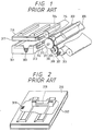
- Fig. 1 of the drawings is a perspective view illustrating the construction of the conventional printer
- Fig. 2 is a perspective view showing the construction of the paper discharging mechanism.
- 301 represents a paper cassette for Storing the recording paper
- 302 indicates the recording paper stored in the inside of this paper cassette
- 303 denotes the platen roller around which the recording paper 302 is wound at the time of transferring the images
- 304 shows a clamper set for its free movement in the direction R of the radius of the platen roller 303 mentioned above
- 305 marks the thermal printing head which performs the transfer of images onto the recording paper 302.
- 314 represents an ink sheet, which is stored inside the ink cassette not shown in the Figures but stored inside the ink cassette, and this ink sheet 314 is made of transparent film coated with ink.
- 315 indicates the paper detecting sensor.
- 316 shows the upper cover for the paper discharging mechanism, and 318 shows a slider which pushes the recording paper 302 to the front face of the printer.
- 319 represents the optical sensor which detects the recording paper 302 upon its arrival at the prescribed position in the paper discharging mechanism.
- Fig. 3 shows the state of paper feeding.
- the recording paper 302 is transported forward and passes through the position of the paper detecting sensor 315.
- the paper detecting sensor 315 detects the passage of the recording paper 302 and generates a signal as shown in Fig. 6.
- the recording paper 302 is inserted between the clamper 304 and the platen roller 303.
- the clamper 304 moves in the direction R 1 towards the center of the platen roller 303, after the above-mentioned A seconds after the paper detecting sensor 315 generates the signal, and holds the recording paper 302 on the platen roller 303 by applying pressure to the said paper. Subsequently, the motor 306 revolves, and its motion is transmitted to the platen roller 303 via the gear 307, the gear 308, the gear 309, and the gear 310, and, with the rotation of the said platen roller 303 in the direction shown by the arrow mark b, the recording paper 302 is wound around the outer circumference of the platen roller 303.
- the said thermal printing head temporarily evacuates upwards lest it should interfere with the said movement of the clamper 304.
- Fig. 5 shows the state of the discharge of the recording paper.
- the platen roller 303 moves in reverse in the direction shown by the arrow mark c in the Figure, and the recording paper 302 is then guided by the paper discharging guides are not shown in the Figure and is transported to the paper discharging mechanism by the paper discharging roller 313. While this operation is being performed, the slider 318 is in its home position as shown in Fig. 7.
- the optical sensor 319 detects the recording paper 302.
- the slider 318 shifts its position in the direction A by means of the driving mechanism not shown in the Figure, pushing the paper in the direction A.
- the recording paper 302 pops out of the front panel not illustrated in the Figure, when the slider 318 has moved to the second position as shown in Fig. 9, and the paper discharging operation is finished thereupon.
- the slider 318 moves in the direction B, returning to its home position.
- the conventional printer is constructed as described above. Yet, as static electricity is generated on the recording paper after the transfer of images onto it, the recording paper 302 may sometimes be stuck to the upper cover of the paper discharging mechanism, in which case it is highly probable that a jam of the paper happens. Also, the conventional printer is liable to the problem that its construction causes considerable difficulty in removing the jammed paper in case a jam of paper has occurred inside its paper discharging mechanism.
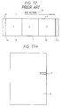
- Fig. 10 is a perspective view illustrating the construction and operations of a paper discharging mechanism of a conventional printer.
- 401 represents the recording paper
- 402 marks the guide, which has a slope 402a as illustrated in the said Figure.
- 403a and 403b are transporting rollers forming a pair and provided in the upper and lower positions respectively, and these rollers are supported in a manner permitting their free rotating motion in the positions shown in the Figure.
- the transporting roller 403a mentioned above is given its force to work on the transporting roller 403b mentioned above by a force providing means not shown in the Figure.
- 404 indicates a motor, which works as the driving means for the transporting roller 403b mentioned above, and the pulley 406, which is fixed on the shaft of the motor 404 mentioned above, and 406 is a pulley fixed on the shaft of the above-mentioned transporting roller 403b.
- 407 is a wire, which is the means of transmitting the revolving force of the motor 404 from the pulley 405 mentioned above to the pulley 406 mentioned above.
- 408 is the upper cover for the above-ment
- the revolving power of the motor 404 is transmitted to the transporting roller 403b by way of the pulley 405, the wire 407, and the pulley 406, and, as the result of this transmission of the power, the transporting rollers 403a and 403b rotate respectively in the direction shown by the arrow mark a and the direction shown by the arrow mark b.
- the forward end of the recording paper 401 is put between the transporting rollers 403a and 403b, and the recording paper 401 is transported forward in the direction shown by the arrow mark c, being thereby pushed out onto the slope 402a.
- the recording paper 401 When the recording paper 401 is thus pushed out to the full extent by the transporting rollers 403a and 403b, the recording paper 401 is released from the capture by the above-mentioned transporting rollers 403a and 403b, so that the paper glides down the slope 402a mentioned above to be delivered out of the lower area of the guide 402.
- the conventional paper discharging mechanism occasionally fails to discharge the paper with certainty since the recording paper sometimes does not slide well over the slope because of a difference in the coefficient of friction between the recording paper and the surface of the slope or since the recording paper sometimes stick to the slope in consequence of static electricity generated thereon.
- a discharging mechanism which operates with a separately provided discharging block, is employed to apply the driving force to discharge the recording paper as pushed out onto the guide by the transporting rollers.
- the mechanism is liable to make an error in its operation in that the paper discharging block may set into its operation although the recording paper is not yet fully released, on account of various factors, from its engagement in the transporting rollers.
- a jam of paper may occur as the result of the capture of the fringe of the paper in the guide or the upper cover in consequence of the skew of the recording paper at the time when the paper discharging block is put into its operation
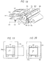
- Figs. 11 to Fig. 17 illustrate an example of the paper transporting method incorporated in a conventional ordinary color thermal printer.
- 501 indicates the recording paper on which information is to be transferred in the form of printed images
- 501 marks the clamper which grips and transports the recording paper 501
- 503 represents the platen roller for winding the recording paper 501 around it and for transporting the recording paper 501 and the ink sheet.
- 504 indicates an ink sheet, which places color on the recording paper 501
- 505 shows the roller for transporting the ink sheet.
- 506 marks the thermal printing head, which performs the transfer of images to the recording paper 501 by putting the ink sheet 504 against the said paper and applying heat to the said ink sheet.
- 507a and 507b show the paper feeding rollers, which transport the recording paper 501 from an outside area into the printer mechanism.
- 508a and 508b indicate the paper discharging rollers, which transport the recording paper 501 to the outside area.
- Fig. 17 illustrates the color pattern for one image screen area, and, in this pattern, 510 shows the area for Y (yellow), 511 shows the area for M (magenta), and 513 shows the area for C (cyan). 515a and 515b represent the detecting part of the sensor.
- Fig. 11 shows the state of paper feeding.
- the recording paper 501 is transported by the paper feeding rollers 507a and 507b to move forward to the clamper 502.
- the clamper which has been open to the outside, closes toward the inner area, clamping the fore end of the recording paper 501.
- the platen roller 503 begins its rotation in the counterclockwise direction, winding the recording paper 501 around the platen roller 503.
- the thermal printing head 506 comes down by rotation and put the ink sheet 504 into close contact with the recording paper 501 wound around the platen roller 503.
- the thermal printing head 506 temporarily shifts its position upward in order that it will not interfere with the passage of the clamper 502, and, when the clamper 502 finishes its passage, the thermal printing head 506 moves down as shown in Fig. 12, and the ink in M (magenta) is transferred this time from the ink sheet 504 to print the images in the same manner as in the transfer of Y (yellow).
- the clamper When the thermal printing head 506 comes down after the passage of the clamper 502 after the completion of the transfer of the images in M (magenta), the clamper operates to form the state of its opening to the outside, as shown in Fig. 14, and, as the images continue to be printed in the final color, C (cyan), with the ink applied from the ink sheet 504, the recording paper 501 arrives at the paper discharging rollers 508a and 508b, and the recording paper is transported to the outside area by the rotation of the said rollers.
- Fig. 16 and Fig. 15 illustrate the state with the case for the ink sheet removed.
- the recording paper 501 which has become free at the time of its discharge fails to move forward together with the ink sheet 504 in the course of the transfer of images onto it because of the resistance the paper receives from the guide, etc., and this lag in the movement of the paper works as a factor causing such defects as a deviation of colors.
- this object is obtained by providing a printer specified in claim 1.
- the recording sheet is sometimes called recording paper.
- the mechanism according to the present invention makes it possible to remove the jammed recording paper with ease by moving the recording paper in the direction A shown in Fig. 19 with a hand put into the mechanism through the opening 361 provided in the paper discharging mechanism and subsequently, when the paper is put into the state shown in Fig. 20, by moving the said paper in the direction B.
- the dimensions of the opening 361 in the upper cover are set smaller than the dimensions of the recording paper, and it is thus made possible constantly to guide the four corners of the recording paper 301 with the upper cover 316, and this feature eliminates the paper jams likely to be otherwise caused by the provision of the opening 361.
- the enlargement of the dimensions of the opening 361 to a size somewhat smaller than the dimensions of the recording paper 302 makes it possible to prevent the occurrence of the phenomenon that the recording paper sticks to the upper cover 316 of the paper discharging mechanism by the effect of static electricity generated on the recording paper after the transfer of images to it and therefore makes it possible to discharge the recording paper in an unfailing way.
- a cylinder-shaped guide 316a is provided in the opening of the mechanism according to the present invention, and this structure prevents the hand from its accidental insertion into the dangerous parts, such as the high tension blocks, in the set when the hand is put into the mechanism from the outside of the set and also serves the purpose of strengthening the rigidity of the upper cover 316 of the paper discharging mechanism.
- the seventh example of preferred embodiments according to the present invention is provided with an opening in the upper cover of the paper discharging mechanism, so that it is possible easily to remove the jammed paper in case a jam has occurred inside the paper discharging mechanism and also offers the advantageous effect of preventing the recording paper from sticking to the upper cover of the paper discharging mechanism by the action of static electricity developed on the paper after the transfer of images to it.
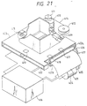
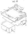
- Fig. 21 is a perspective view with some part cut away in illustration of the printer according to a further preferred embodiment of the present invention
- Fig. 22 is a perspective view illustrating only those members actually put into operation and the construction of the driving mechanism which performs control over those members in the example of the referred embodiment illustrated in Fig. 21
- Fig. 23 is a perspective view with some part cut away showing the parts, excluding the driving mechanism shown in Fig. 21, as disassembled.
- the reference numbers 401 through 408 represent the parts which are either the same as or corresponding to the parts in the conventional printer described above and shown in Fig. 10. Hence, these parts are merely indicated by the same reference numbers, and their description is omitted here.
- the reference number 409 indicates the paper discharging block, which can be put into its sliding movement along the groove in the guide 402 mentioned above, and the reference number 410 denotes the motor, which forms the driving means for setting the above-mentioned paper discharging block 409 into its sliding movement.
- the reference number 411 indicates the pulley mounted axially on the shaft of the motor 410 mentioned above.
- the reference numbers 412 and 413 indicate the pulleys respectively supported in such a way as to permit their free rotation on a shaft not illustrated in the Figure.
- the reference number 414 shows the wire, both ends of which are fixed on the paper discharging block 409 mentioned above and formed into a loop by way of the pulley 411, the pulley 412 and pulley 413 mentioned above, and this wire serves as the transmitting means for the transmission of the driving power to the paper discharging block 409 mentioned above.
- the reference number 415 shows the photoelectric switch
- the reference numbers 416 shows the control circuit
- the reference numbers 417, 418, and 419 indicate the paper holding members.
- the parts of these paper holding members which actually get into contact with the recording paper 401 are made of elastic substance, and these paper holding members are capable of applying adequate pressing pressure to the recording paper 401 mentioned above, thereby correcting the skew of the recording paper 401, when it passes through in contact with the above-mentioned paper holding members 407, 418, and 419 and the guide 402.
- the paper holding members 417 and 418 mentioned above correct the skew of the recording paper 401 the mentioned above at the time when the said paper is transported by the above-mentioned transporting rollers 403a and 403b
- the paper holding member 419 corrects the skew of the above-mentioned recording paper 401 when the said paper 401 is discharged by the above-mentioned paper discharging block.
- the revolving power of the motor 404 is transmitted to the transporting roller 403b via the pulley 405, the wire 407, and the pulley 406, and, as the result of the transmission, the transporting rollers 403a and 403b are rotated respectively in the direction indicated by the arrow mark a and in the direction indicated by the arrow mark b, and, when the top edge of the recording paper 401 is fed into the slit between the transporting roller 403a and the transporting roller 403b, the recording paper 401 is transported in the direction indicated by the arrow mark c, having its skew corrected in this process of transport, and is then pushed out onto the guide 402.
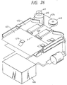
- the control circuit 416 stops the revolution of the motor 404. Subsequently, as illustrated in Fig. 26, the control circuit 416 starts the motor 410 for its revolution, and the revolving power of the motor 410 is transmitted to the paper discharging block 409 through the pully 411,412 and 413 not shown and the wire 414, and, as the result, the paper discharging block 409 proceeds in sliding motion in the direction indicated by the arrow mark d, pushing the sides of the recording paper 401 on the guide 402.
- the recording paper 401 is discharged while its skew is corrected by the paper holding member 419.
- the motor 410 revolves in reverse, under control by the control circuit 416, in order to push the block 409 into its sliding movement in the direction opposite to the direction for the discharge of the recording paper 401 (i.e. in the direction indicated by the arrow mark d), and the motor 410 stops when the paper discharging block 409 is thus evacuated into its normal position.
- the paper handling mechanism according to the present invention is so constructed as described above that it is capable of performing the discharge of the recording paper with certainty through prevention of such troubles as the jamming of paper since the printer performance of the discharge of the recording paper only after the recording paper is released completely from its capture by the transporting rollers after the full completion of the transport of the recording paper and performs all the operations while correcting the skew of the recording paper, performing the discharge of the recording paper.
- the process for the transfer of images in Y (yellow), M (magenta), and C (cyan) is performed by the repetition of a cycle of exactly the same operations, as shown in Fig. 12 and Fig. 14.
- the thermal printing head 506 moves down to the recording paper 501 wound around the platen roller 503 and sets the ink sheet 504 into its close contact with the recording paper 501, and, as heat is applied to the heater line for the thermal printing head 503, each of the colors is transferred to the recording paper 501 in overlapping to a total of three applications.
- the clamper 502 When the thermal printing head 506 moves down upon the completion of the passage of the clamper 502 following the completion of the transfer of images in C (cyan), which is the color to be applied finally, the clamper 502 is set into a state of its opening to the outside, and, the clamper 502 remaining in this state, the recording paper 501 is transported, together with the transparent part of the ink sheet 504, in the direction towards the paper discharging rollers 508a and 508b, and, when the recording paper 501 reaches the paper discharging rollers 508a and 508b, the said paper is transported to the outside.
- C cyan
Description
In addition, the enlargement of the dimensions of the
Claims (9)
- A printer comprising means for transferring an image onto a recording sheet that is transported from an input path to a printing station and from said printing station to an output path,
wherein said output path comprising a discharge mechanism for receiving said recording sheet in said processing flow direction and moving means (409) for moving said recording sheet in a direction substantially orthogonal to said processing flow direction;
characterized in thatsaid discharge mechanism comprises a discharge opening disposed so that said moving means (409) is operable to move the recording sheet through said opening and to discharge said recording sheet from said printer; anda recording sheet holding member (419) is provided for correcting a skew of said recording sheet when it is discharged by said moving means through said opening. - The printer as set forth in claim 1, characterized in that said moving means (409) comprises a pusher mechanism.
- The printer as set forth in claim 1 or 2, characterized in that said recording sheet holding member (419) is disposed proximate said opening.
- The printer as set forth in any of claims 1 to 3, characterized in that said holding member (419) is made of elastic substance.
- The printer as set forth in any of claims 1 to 4, characterized in thatsaid discharge mechanism comprises a cover (408) disposed at a position where said said orthogonal direction intersects said processing flow direction; andsaid cover (408) includes a jam clearing access hole located therein proximate the position of intersection of said processing flow direction and said orthogonal direction.
- The printer as set forth in claim 5, characterized in that said jam clearing access hole is sized to permit access at least by an operator finger, but is maller than the area defined by the size of the recording sheet.
- The printer as set forth in claim 5 or 6, characterized in that said jam clearing access hole is disposed on said cover (408).
- The printer as set forth in any of claim 5 to 7, characterized in that said jam clearing access hole is surrounded by a collar-shaped guide extending perpendicular from said cover (408).
- The printer as set forth in any of claim 5 to 8, characterized in that said cover (408) comprising said jam clearing access hole, further comprises static electricity reducing means.
Applications Claiming Priority (21)
| Application Number | Priority Date | Filing Date | Title |
|---|---|---|---|
| JP1114631A JPH02293184A (en) | 1989-05-08 | 1989-05-08 | Ink sheet of color thermal printer |
| JP114631/89 | 1989-05-08 | ||
| JP154906/89 | 1989-06-15 | ||
| JP1154906A JP2586137B2 (en) | 1989-06-15 | 1989-06-15 | Printer device |
| JP215240/89 | 1989-08-21 | ||
| JP1215239A JP2587111B2 (en) | 1989-08-21 | 1989-08-21 | Printer device |
| JP1215240A JP2587112B2 (en) | 1989-08-21 | 1989-08-21 | Printer device |
| JP215239/89 | 1989-08-21 | ||
| JP1989097544U JP2566942Y2 (en) | 1989-08-21 | 1989-08-21 | Printer device |
| JP97544/89U | 1989-08-21 | ||
| JP19449/90 | 1990-01-29 | ||
| JP2019449A JP2841622B2 (en) | 1990-01-29 | 1990-01-29 | Printer device |
| JP52111/90 | 1990-03-02 | ||
| JP52103/90 | 1990-03-02 | ||
| JP2052103A JP2619100B2 (en) | 1990-03-02 | 1990-03-02 | Printer device |
| JP2052111A JP2556165B2 (en) | 1990-03-02 | 1990-03-02 | Printer device |
| JP27518/90 | 1990-03-16 | ||
| JP2751890U JPH03118651U (en) | 1990-03-16 | 1990-03-16 | |
| JP2092640A JPH03293254A (en) | 1990-04-06 | 1990-04-06 | Printer unit |
| JP92640/90 | 1990-04-06 | ||
| EP90108669A EP0403775B1 (en) | 1989-05-08 | 1990-05-08 | Printer |
Related Parent Applications (2)
| Application Number | Title | Priority Date | Filing Date |
|---|---|---|---|
| EP90108669A Division EP0403775B1 (en) | 1989-05-08 | 1990-05-08 | Printer |
| EP90108669.4 Division | 1990-05-08 |
Publications (3)
| Publication Number | Publication Date |
|---|---|
| EP0580184A2 EP0580184A2 (en) | 1994-01-26 |
| EP0580184A3 EP0580184A3 (en) | 1995-12-20 |
| EP0580184B1 true EP0580184B1 (en) | 1998-12-16 |
Family
ID=27579706
Family Applications (4)
| Application Number | Title | Priority Date | Filing Date |
|---|---|---|---|
| EP93113596A Expired - Lifetime EP0580183B1 (en) | 1989-05-08 | 1990-05-08 | Printer |
| EP93113597A Expired - Lifetime EP0580184B1 (en) | 1989-05-08 | 1990-05-08 | Printer |
| EP93113595A Expired - Lifetime EP0580182B1 (en) | 1989-05-08 | 1990-05-08 | Printer |
| EP90108669A Expired - Lifetime EP0403775B1 (en) | 1989-05-08 | 1990-05-08 | Printer |
Family Applications Before (1)
| Application Number | Title | Priority Date | Filing Date |
|---|---|---|---|
| EP93113596A Expired - Lifetime EP0580183B1 (en) | 1989-05-08 | 1990-05-08 | Printer |
Family Applications After (2)
| Application Number | Title | Priority Date | Filing Date |
|---|---|---|---|
| EP93113595A Expired - Lifetime EP0580182B1 (en) | 1989-05-08 | 1990-05-08 | Printer |
| EP90108669A Expired - Lifetime EP0403775B1 (en) | 1989-05-08 | 1990-05-08 | Printer |
Country Status (3)
| Country | Link |
|---|---|
| US (8) | US5433544A (en) |
| EP (4) | EP0580183B1 (en) |
| DE (4) | DE69032564T2 (en) |
Families Citing this family (31)
| Publication number | Priority date | Publication date | Assignee | Title |
|---|---|---|---|---|
| DE69213484T2 (en) * | 1991-01-12 | 1997-02-06 | Samsung Electronics Co Ltd | Paper clamp |
| US5353049A (en) * | 1991-01-12 | 1994-10-04 | Samsung Electronics Co., Ltd. | Paper holder of video printer |
| KR920016254A (en) * | 1991-02-12 | 1992-09-24 | 강진구 | Video printer devices |
| KR950011933B1 (en) * | 1991-10-16 | 1995-10-12 | 삼성전자주식회사 | Video printer holder device |
| DE69222034T2 (en) * | 1992-06-04 | 1998-01-08 | Samsung Electronics Co Ltd | Paper holder for a video printer |
| EP0586351A3 (en) * | 1992-08-31 | 1994-06-29 | Canon Kk | Ink ribbon winding member for a recording apparatus |
| JPH08174958A (en) * | 1994-12-26 | 1996-07-09 | Brother Ind Ltd | Ink jet type print recorder |
| JP3370517B2 (en) * | 1996-06-14 | 2003-01-27 | ペンタックス株式会社 | Thermal line printer structure |
| US5762431A (en) * | 1997-02-10 | 1998-06-09 | Datacard Corporation | Thermal printer and method for using |
| US5886726A (en) * | 1997-02-10 | 1999-03-23 | Datacard Corporation | Thermal print head module and method for using |
| US5758981A (en) * | 1997-06-16 | 1998-06-02 | Hewlett-Packard Company | Print media ejection kicking after paper drop |
| EP1029429A4 (en) * | 1997-09-15 | 2001-10-10 | Berg Tech Inc | Electronic card with rf extension |
| JP3719334B2 (en) * | 1997-10-02 | 2005-11-24 | セイコーエプソン株式会社 | Winding shaft and printer using the same |
| US6493018B1 (en) | 1999-04-08 | 2002-12-10 | Gerber Scientific Products, Inc. | Wide format thermal printer |
| US6439688B1 (en) | 1999-04-30 | 2002-08-27 | Hewlett-Packard Company | Technique for printing a bar code while conserving colorant |
| US6406200B2 (en) | 1999-07-30 | 2002-06-18 | Inovise Medical, Inc. | Printer assembly with lateral and longitudinal self-alignment |
| US6631902B1 (en) | 2000-03-30 | 2003-10-14 | Hewlett-Packard Development Company, L.P. | Media storage bin and method of using same |
| JP2002137468A (en) * | 2000-08-24 | 2002-05-14 | Sharp Corp | Ink jet imaging apparatus |
| WO2002096667A1 (en) * | 2001-05-28 | 2002-12-05 | Fuji Photo Film Co., Ltd. | Laser thermal transfer recording method |
| KR20020091750A (en) * | 2001-05-30 | 2002-12-06 | 가부시키가이샤 웨지 | Image recording apparatus, thermal transfer ink ribbon and thermal transfer ink ribbon cassette used in this image recording apparatus |
| JP3913720B2 (en) * | 2003-07-22 | 2007-05-09 | 三洋電機株式会社 | Printing device |
| JP2007230701A (en) * | 2006-02-28 | 2007-09-13 | Brother Ind Ltd | Printer |
| EP2111529B1 (en) | 2006-10-23 | 2015-08-26 | J.A. Woollam Co. Inc. | Directing a Beam of Electromagnetic Radiation into the end of an Optical Fibre Using Output from a Multiple Element Detector |
| CN101434151B (en) * | 2007-11-13 | 2010-10-13 | 旭丽电子(广州)有限公司 | Heat sublimation printer |
| JP2011075791A (en) * | 2009-09-30 | 2011-04-14 | Fujifilm Corp | Printer and printing method |
| JP5422458B2 (en) * | 2010-03-25 | 2014-02-19 | 富士フイルム株式会社 | Medium conveying apparatus, image forming apparatus, and medium conveying method |
| US9275093B2 (en) | 2011-01-28 | 2016-03-01 | Cisco Technology, Inc. | Indexing sensor data |
| US9171079B2 (en) * | 2011-01-28 | 2015-10-27 | Cisco Technology, Inc. | Searching sensor data |
| WO2012148402A1 (en) * | 2011-04-28 | 2012-11-01 | Hewlett-Packard Development Company, L.P. | Print media gripper arrangement |
| EP2864124B1 (en) | 2012-06-26 | 2020-06-10 | Hewlett-Packard Development Company, L.P. | Print media guide |
| CN113023434B (en) * | 2021-03-09 | 2023-01-31 | 威海市泰宇印刷包装材料有限公司 | Non-stop printing device |
Family Cites Families (37)
| Publication number | Priority date | Publication date | Assignee | Title |
|---|---|---|---|---|
| FR2199237B1 (en) * | 1972-09-14 | 1975-03-14 | Cit Alcatel | |
| US3906512A (en) * | 1972-12-29 | 1975-09-16 | Minnesota Mining & Mfg | Mechanical drum positioning and sheet-clamping mechanism for facsimile |
| DE2607774C3 (en) * | 1976-02-26 | 1980-01-31 | Hoechst Ag, 6000 Frankfurt | Device for controllably holding originals on a moving support surface of a photocopier |
| JPS5483275A (en) * | 1977-12-14 | 1979-07-03 | Canon Kk | Paper surface detector |
| CH641112A5 (en) * | 1979-10-17 | 1984-02-15 | Grapha Holding Ag | FEEDER FOR PRINTED SHEET. |
| JPS5661255A (en) * | 1979-10-24 | 1981-05-26 | Ricoh Co Ltd | Winder of paper web |
| US4259695A (en) * | 1979-12-03 | 1981-03-31 | Matsushita Graphic Communication Systems, Inc. | Facsimile sheet clamping device |
| JPS57174784A (en) * | 1981-04-22 | 1982-10-27 | Hitachi Ltd | Processor of recording medium |
| EP0073132A3 (en) * | 1981-08-17 | 1985-08-28 | Mccorquodale Machine Systems Limited | Printing in register on sheets |
| JPS58148779A (en) * | 1982-03-02 | 1983-09-03 | Sony Corp | Printer |
| JPS59109393A (en) * | 1982-12-15 | 1984-06-25 | Shinko Electric Co Ltd | Transfer printing method |
| JPS59215880A (en) * | 1983-05-25 | 1984-12-05 | Canon Inc | Recorder |
| JPS6072759A (en) * | 1983-09-30 | 1985-04-24 | Fujitsu Ltd | Print driving for color printer and color ink sheet thereof |
| JPS6085975A (en) * | 1983-10-18 | 1985-05-15 | Matsushita Electric Ind Co Ltd | Color typewriter |
| US4665408A (en) * | 1983-11-29 | 1987-05-12 | Minolta Camera Kabushiki Kaisha | Image recording apparatus for transporting photosensitive film sheet |
| JPS60260363A (en) * | 1984-06-08 | 1985-12-23 | Ricoh Co Ltd | Recording system of thermal transfer type printer |
| JPS6131270A (en) * | 1984-07-25 | 1986-02-13 | Hitachi Ltd | Hard copying device |
| JPS6151391A (en) * | 1984-08-20 | 1986-03-13 | Toshiba Corp | Thermal transfer recording medium and its apparatus |
| JPH0425344Y2 (en) * | 1984-10-27 | 1992-06-17 | ||
| JPS62124991A (en) * | 1985-11-26 | 1987-06-06 | Olympus Optical Co Ltd | Thermal transfer ink sheet and thermal transfer printer using the same |
| JPH0651416B2 (en) * | 1986-01-21 | 1994-07-06 | スガイ化学工業株式会社 | Ink ribbon for thermal transfer recording |
| JPS62212491A (en) * | 1986-03-13 | 1987-09-18 | Konishiroku Photo Ind Co Ltd | Method of radiation image transformation and radiation image transformation panel for use in said method |
| US4734868A (en) * | 1986-07-21 | 1988-03-29 | Vfn Technology Inc. | Precision paper transport system |
| JPS6339364A (en) * | 1986-08-04 | 1988-02-19 | Matsushita Electric Ind Co Ltd | Thermal transfer recorder |
| US4898488A (en) * | 1986-08-22 | 1990-02-06 | Brother Kogyo Kabushiki Kaisha | Printer with multi-function paper feeding mechanism |
| JPS6353075A (en) * | 1986-08-22 | 1988-03-07 | Matsushita Electric Ind Co Ltd | Paper feeder |
| JPS6353070A (en) * | 1986-08-25 | 1988-03-07 | Hitachi Ltd | Thermal transfer recorder |
| JPS63125376A (en) * | 1986-11-13 | 1988-05-28 | Mitsubishi Electric Corp | Thermal transfer ink ribbon |
| US4900008A (en) * | 1986-12-22 | 1990-02-13 | Polaroid Corporation | Sheet clamping arrangement for rotatable drums |
| JP2590477B2 (en) * | 1987-05-13 | 1997-03-12 | 富士ゼロックス株式会社 | Paper transport direction change device |
| US4893134A (en) * | 1987-09-04 | 1990-01-09 | Minolta Camera Kabushiki Kaisha | Thermal transfer recording apparatus |
| JPH074955B2 (en) * | 1987-12-22 | 1995-01-25 | 日本ビクター株式会社 | Thermal transfer printer |
| JPH01249477A (en) * | 1988-03-31 | 1989-10-04 | Sony Corp | Printer |
| JPH01320176A (en) * | 1988-06-22 | 1989-12-26 | Hitachi Ltd | Recording paper fixing device in printer |
| JPH0255172A (en) * | 1988-08-22 | 1990-02-23 | Nec Corp | Printer control system |
| DE3906612A1 (en) * | 1989-03-02 | 1990-09-06 | Philips Patentverwaltung | OFFICE MACHINE, e.g. PRINTER |
| JP2735286B2 (en) * | 1989-04-26 | 1998-04-02 | 株式会社日立製作所 | Paper positioning mechanism |
-
1990
- 1990-05-08 DE DE69032564T patent/DE69032564T2/en not_active Expired - Fee Related
- 1990-05-08 EP EP93113596A patent/EP0580183B1/en not_active Expired - Lifetime
- 1990-05-08 DE DE69032565T patent/DE69032565T2/en not_active Expired - Fee Related
- 1990-05-08 EP EP93113597A patent/EP0580184B1/en not_active Expired - Lifetime
- 1990-05-08 EP EP93113595A patent/EP0580182B1/en not_active Expired - Lifetime
- 1990-05-08 DE DE69032842T patent/DE69032842T2/en not_active Expired - Fee Related
- 1990-05-08 DE DE69018319T patent/DE69018319T2/en not_active Expired - Fee Related
- 1990-05-08 EP EP90108669A patent/EP0403775B1/en not_active Expired - Lifetime
-
1993
- 1993-04-27 US US08/053,016 patent/US5433544A/en not_active Expired - Fee Related
- 1993-04-27 US US08/052,676 patent/US5421661A/en not_active Expired - Fee Related
- 1993-04-27 US US08/052,669 patent/US5421660A/en not_active Expired - Fee Related
- 1993-12-16 US US08/167,160 patent/US5431503A/en not_active Expired - Fee Related
-
1995
- 1995-04-17 US US08/422,939 patent/US5562354A/en not_active Expired - Fee Related
- 1995-05-01 US US08/431,756 patent/US5645362A/en not_active Expired - Fee Related
- 1995-05-01 US US08/431,749 patent/US5547297A/en not_active Expired - Fee Related
- 1995-05-01 US US08/431,750 patent/US5873665A/en not_active Expired - Fee Related
Also Published As
| Publication number | Publication date |
|---|---|
| EP0580182B1 (en) | 1998-08-12 |
| US5421661A (en) | 1995-06-06 |
| DE69018319T2 (en) | 1995-09-14 |
| EP0580182A2 (en) | 1994-01-26 |
| DE69032842D1 (en) | 1999-01-28 |
| DE69032565D1 (en) | 1998-09-17 |
| EP0403775A3 (en) | 1991-03-13 |
| DE69032564T2 (en) | 1999-01-28 |
| EP0580183A2 (en) | 1994-01-26 |
| EP0580183B1 (en) | 1998-08-12 |
| US5645362A (en) | 1997-07-08 |
| DE69032842T2 (en) | 1999-06-02 |
| DE69018319D1 (en) | 1995-05-11 |
| US5433544A (en) | 1995-07-18 |
| DE69032564D1 (en) | 1998-09-17 |
| EP0403775B1 (en) | 1995-04-05 |
| US5873665A (en) | 1999-02-23 |
| US5431503A (en) | 1995-07-11 |
| DE69032565T2 (en) | 1999-01-28 |
| EP0580183A3 (en) | 1996-01-10 |
| EP0580184A3 (en) | 1995-12-20 |
| EP0580184A2 (en) | 1994-01-26 |
| US5547297A (en) | 1996-08-20 |
| US5421660A (en) | 1995-06-06 |
| EP0403775A2 (en) | 1990-12-27 |
| US5562354A (en) | 1996-10-08 |
| EP0580182A3 (en) | 1996-01-03 |
Similar Documents
| Publication | Publication Date | Title |
|---|---|---|
| EP0580184B1 (en) | Printer | |
| GB2141385A (en) | Image forming device | |
| US4506881A (en) | Duplexing paper handling system | |
| EP0216350B1 (en) | Recording apparatus | |
| JPH03286880A (en) | Color printer | |
| JP2000052578A (en) | Thermal transfer recorder | |
| CA1221871A (en) | Paper handling system | |
| JP2619100B2 (en) | Printer device | |
| JPS6271674A (en) | Recorder | |
| JP2912272B2 (en) | Thermal transfer recording device that records by winding paper around the paper transport drum | |
| JPS6271676A (en) | Recorder | |
| JPH04173168A (en) | Transfer image recording device | |
| JPH02286273A (en) | Thermal transfer-type printer | |
| JPH01301275A (en) | Hard copying machine | |
| JPS60250974A (en) | Thermal transfer type recorder | |
| JPS6019625A (en) | Recording device | |
| JPS6271675A (en) | Recorder | |
| JPH0386567A (en) | Printer device | |
| JPH04173167A (en) | Sheet supply of image recording device | |
| JPS6271677A (en) | Recorder | |
| JPS63107574A (en) | Thermal transfer type color printer | |
| JPS6271671A (en) | Recorder | |
| JPH03224766A (en) | Color printer | |
| JPS6274853A (en) | Paper transfer device | |
| JPH04159944A (en) | Thermal printer device |
Legal Events
| Date | Code | Title | Description |
|---|---|---|---|
| PUAI | Public reference made under article 153(3) epc to a published international application that has entered the european phase |
Free format text: ORIGINAL CODE: 0009012 |
|
| AC | Divisional application: reference to earlier application |
Ref document number: 403775 Country of ref document: EP |
|
| AK | Designated contracting states |
Kind code of ref document: A2 Designated state(s): DE FR GB |
|
| PUAL | Search report despatched |
Free format text: ORIGINAL CODE: 0009013 |
|
| RHK1 | Main classification (correction) |
Ipc: B41J 13/00 |
|
| AK | Designated contracting states |
Kind code of ref document: A3 Designated state(s): DE FR GB |
|
| 17P | Request for examination filed |
Effective date: 19960130 |
|
| 17Q | First examination report despatched |
Effective date: 19960506 |
|
| GRAG | Despatch of communication of intention to grant |
Free format text: ORIGINAL CODE: EPIDOS AGRA |
|
| GRAG | Despatch of communication of intention to grant |
Free format text: ORIGINAL CODE: EPIDOS AGRA |
|
| GRAH | Despatch of communication of intention to grant a patent |
Free format text: ORIGINAL CODE: EPIDOS IGRA |
|
| GRAH | Despatch of communication of intention to grant a patent |
Free format text: ORIGINAL CODE: EPIDOS IGRA |
|
| GRAA | (expected) grant |
Free format text: ORIGINAL CODE: 0009210 |
|
| AC | Divisional application: reference to earlier application |
Ref document number: 403775 Country of ref document: EP |
|
| AK | Designated contracting states |
Kind code of ref document: B1 Designated state(s): DE FR GB |
|
| REF | Corresponds to: |
Ref document number: 69032842 Country of ref document: DE Date of ref document: 19990128 |
|
| ET | Fr: translation filed | ||
| PLBE | No opposition filed within time limit |
Free format text: ORIGINAL CODE: 0009261 |
|
| STAA | Information on the status of an ep patent application or granted ep patent |
Free format text: STATUS: NO OPPOSITION FILED WITHIN TIME LIMIT |
|
| 26N | No opposition filed | ||
| REG | Reference to a national code |
Ref country code: GB Ref legal event code: IF02 |
|
| PGFP | Annual fee paid to national office [announced via postgrant information from national office to epo] |
Ref country code: GB Payment date: 20030507 Year of fee payment: 14 |
|
| PGFP | Annual fee paid to national office [announced via postgrant information from national office to epo] |
Ref country code: FR Payment date: 20030508 Year of fee payment: 14 |
|
| PGFP | Annual fee paid to national office [announced via postgrant information from national office to epo] |
Ref country code: DE Payment date: 20030515 Year of fee payment: 14 |
|
| PG25 | Lapsed in a contracting state [announced via postgrant information from national office to epo] |
Ref country code: GB Free format text: LAPSE BECAUSE OF NON-PAYMENT OF DUE FEES Effective date: 20040508 |
|
| PG25 | Lapsed in a contracting state [announced via postgrant information from national office to epo] |
Ref country code: DE Free format text: LAPSE BECAUSE OF NON-PAYMENT OF DUE FEES Effective date: 20041201 |
|
| GBPC | Gb: european patent ceased through non-payment of renewal fee |
Effective date: 20040508 |
|
| PG25 | Lapsed in a contracting state [announced via postgrant information from national office to epo] |
Ref country code: FR Free format text: LAPSE BECAUSE OF NON-PAYMENT OF DUE FEES Effective date: 20050131 |
|
| REG | Reference to a national code |
Ref country code: FR Ref legal event code: ST |