EP0578778B1 - Behälter für reibahle/schlüssel/zahnwurzelstift - Google Patents
Behälter für reibahle/schlüssel/zahnwurzelstift Download PDFInfo
- Publication number
- EP0578778B1 EP0578778B1 EP92911294A EP92911294A EP0578778B1 EP 0578778 B1 EP0578778 B1 EP 0578778B1 EP 92911294 A EP92911294 A EP 92911294A EP 92911294 A EP92911294 A EP 92911294A EP 0578778 B1 EP0578778 B1 EP 0578778B1
- Authority
- EP
- European Patent Office
- Prior art keywords
- primary
- tool
- compartment
- lid
- compartments
- Prior art date
- Legal status (The legal status is an assumption and is not a legal conclusion. Google has not performed a legal analysis and makes no representation as to the accuracy of the status listed.)
- Expired - Lifetime
Links
- 230000002452 interceptive effect Effects 0.000 claims 1
- 230000000284 resting effect Effects 0.000 claims 1
- 230000002093 peripheral effect Effects 0.000 abstract description 3
- 238000004513 sizing Methods 0.000 abstract 1
- 239000000463 material Substances 0.000 description 5
- 229920003023 plastic Polymers 0.000 description 3
- 229910052782 aluminium Inorganic materials 0.000 description 2
- XAGFODPZIPBFFR-UHFFFAOYSA-N aluminium Chemical compound [Al] XAGFODPZIPBFFR-UHFFFAOYSA-N 0.000 description 2
- 238000010276 construction Methods 0.000 description 2
- 229910052751 metal Inorganic materials 0.000 description 2
- 239000002184 metal Substances 0.000 description 2
- 230000004048 modification Effects 0.000 description 2
- 238000012986 modification Methods 0.000 description 2
- 239000004033 plastic Substances 0.000 description 2
- 229920000515 polycarbonate Polymers 0.000 description 2
- 239000004417 polycarbonate Substances 0.000 description 2
- 229910000838 Al alloy Inorganic materials 0.000 description 1
- FYYHWMGAXLPEAU-UHFFFAOYSA-N Magnesium Chemical compound [Mg] FYYHWMGAXLPEAU-UHFFFAOYSA-N 0.000 description 1
- 239000004743 Polypropylene Substances 0.000 description 1
- 206010052428 Wound Diseases 0.000 description 1
- 208000027418 Wounds and injury Diseases 0.000 description 1
- 239000004568 cement Substances 0.000 description 1
- 230000001419 dependent effect Effects 0.000 description 1
- 238000006073 displacement reaction Methods 0.000 description 1
- -1 e.g. Inorganic materials 0.000 description 1
- 230000000694 effects Effects 0.000 description 1
- 208000015181 infectious disease Diseases 0.000 description 1
- 238000001746 injection moulding Methods 0.000 description 1
- 230000003993 interaction Effects 0.000 description 1
- 229910052749 magnesium Inorganic materials 0.000 description 1
- 239000011777 magnesium Substances 0.000 description 1
- 238000010137 moulding (plastic) Methods 0.000 description 1
- 229920000379 polypropylene carbonate Polymers 0.000 description 1
- 230000000717 retained effect Effects 0.000 description 1
- 239000007787 solid Substances 0.000 description 1
- 230000001954 sterilising effect Effects 0.000 description 1
- 238000004659 sterilization and disinfection Methods 0.000 description 1
Images




Classifications
-
- B—PERFORMING OPERATIONS; TRANSPORTING
- B65—CONVEYING; PACKING; STORING; HANDLING THIN OR FILAMENTARY MATERIAL
- B65D—CONTAINERS FOR STORAGE OR TRANSPORT OF ARTICLES OR MATERIALS, e.g. BAGS, BARRELS, BOTTLES, BOXES, CANS, CARTONS, CRATES, DRUMS, JARS, TANKS, HOPPERS, FORWARDING CONTAINERS; ACCESSORIES, CLOSURES, OR FITTINGS THEREFOR; PACKAGING ELEMENTS; PACKAGES
- B65D47/00—Closures with filling and discharging, or with discharging, devices
- B65D47/04—Closures with discharging devices other than pumps
- B65D47/20—Closures with discharging devices other than pumps comprising hand-operated members for controlling discharge
- B65D47/26—Closures with discharging devices other than pumps comprising hand-operated members for controlling discharge with slide valves, i.e. valves that open and close a passageway by sliding over a port, e.g. formed with slidable spouts
- B65D47/261—Closures with discharging devices other than pumps comprising hand-operated members for controlling discharge with slide valves, i.e. valves that open and close a passageway by sliding over a port, e.g. formed with slidable spouts having a rotational or helicoidal movement
- B65D47/265—Closures with discharging devices other than pumps comprising hand-operated members for controlling discharge with slide valves, i.e. valves that open and close a passageway by sliding over a port, e.g. formed with slidable spouts having a rotational or helicoidal movement between planar parts
-
- A—HUMAN NECESSITIES
- A61—MEDICAL OR VETERINARY SCIENCE; HYGIENE
- A61C—DENTISTRY; APPARATUS OR METHODS FOR ORAL OR DENTAL HYGIENE
- A61C3/00—Dental tools or instruments
- A61C3/04—Supports for holding tooth drills in order of use
-
- A—HUMAN NECESSITIES
- A61—MEDICAL OR VETERINARY SCIENCE; HYGIENE
- A61C—DENTISTRY; APPARATUS OR METHODS FOR ORAL OR DENTAL HYGIENE
- A61C5/00—Filling or capping teeth
- A61C5/40—Implements for surgical treatment of the roots or nerves of the teeth; Nerve needles; Methods or instruments for medication of the roots
- A61C5/44—Means for controlling working depth, e.g. supports or boxes with depth-gauging means, stop positioners or files with adjustably-mounted handles
Definitions
- This invention lies generally in the field of dental equipment and more particularly relates to a new and improved dental tool container which has novel utility for dentists. More particularly, but not exclusively, the invention provides a dental tool container which is particularly useful for storing and measuring dental posts, post wrenches and reamers and stops, coordinating several of a dentist's requirements in a unique and helpful way.
- Dental tool containers which comprise an annular tool holder; a plurality of primary tool-storage compartments for dental posts which compartments are disposed around the tool holder; a selector lid rotatably mounted on the tool holder and covering the compartments; and a primary opening in the selector lid for accessing said primary compartments; whereby rotation of the selector lid can register said primary opening with each primary compartment in turn, providing access thereto.
- a container is known from US-A-4245742.
- Such tool holders have found widespread acceptance as a convenient means of storing and dispensing dental posts for dental drills.
- reamers are substantially longer than dental posts, requiring longer compartments, creating difficulty in devising a compact container that retains the simplicity and convenience of the prior art.
- Gauges measuring diameter and length have been available as separate items.
- Another object of this invention is to provide such a dental tool container which can store reamers, as well as dental posts, in a simple and compact construction.
- a still further object of this invention is to provide such a dental tool container and associated tools in the form of a novel and useful kit, to make posts, reamers and wrenches conveniently available to a dentist.
- Yet another object of this invention is to provide such a dental tool container which has means to lock the selector lid closed for marketing and distribution.
- a further object is the means to include a stock of reamers of several different sizes in the container, and to provide a convenient means to measure or determine those sizes.
- the present invention provides a dental tool container which comprises: an annular tool holder; a plurality of primary tool-storage compartments for dental posts disposed around the tool holder; a selector lid rotatably mounted on the tool holder and covering the compartments; a primary opening in the selector lid for accessing said primary compartments; whereby rotation of the selector lid can register said primary opening with each primary compartment in turn, providing access thereto; characterised in that the tool container further comprises: a secondary tool storage compartment for dental post wrenches, which secondary compartment is disposed centrally of the tool holder and surrounded by said primary compartments; and a secondary opening in the selector lid for accessing said secondary compartment; whereby rotation of the selector lid on the tool holder can bring the secondary opening therein into and out of registration with said secondary compartment to access it; and in that at least one of said primary compartments is elongated to project centrally inwards beyond others of said primary compartments to provide a reamer compartment to accommodate reamers.
- the secondary compartment most preferably extends in line across the center to abut the reamer compartment.
- a gauge is provided within a primary compartment, preferably opposite the elongated compartment; most preferably, the gauge also extends beyond the inner wall, towards the center and the elongated compartment; an opening is most preferably formed through the outer wall of the container and registering with a slot extending radially along the gauge.
- the container includes a breakaway tab to lock the selector lid in a closed position for marketing and distribution.
- a flexible pawl member extends from the lid and intersects with an indexing ratchet means on the exterior of the outer wall of the container.
- the invention also provides a gauge block in one of the primary compartments which block is adapted for measuring, both radially and longitudinally, tools to be stored in others of said compartments.
- This gauge block can be a close fit in a compartment to be stably supported therein.
- the breakaway tab is adapted to engage the gauge block thereby to lock the selector lid against rotation and to hold the gauge block in its primary compartment.
- a removable plate extends across the lid opening, during storage, in the index ratchet embodiment.
- one of the radial compartments holds stop rings for the reamers; the compartment a perforated bottom to simplify picking up the rings with a reamer.
- the invention also provides a dental tool kit comprising such a dental tool container having at least three different tools loaded in the compartments thereof.
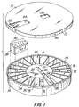
- the dental tool container shown comprises an annular or cylindrical tool holder 10 of circular shape in plan, and a generally circular selector lid 12.
- Directions such as “up” and “down” refer to the disposition of the dental tool container as shown in Fig. 1.
- the tool holder 10 is in the nature of a small circular tray and has a circular outer wall 14 from which radiate inwardly, at regular intervals, a number of dividing walls 16.
- the radial dividing walls 16 define primary tool-storage compartments 18 suitable for storing drill posts, or the like, for use with dental drills.
- the primary compartments 18 are truncated wedge-shaped and arranged in an annulus around the tool holder 10 with their inner walls 22 defining an inner circumferential skirt of a central circular platform 20; the platform top surface can be coplanar with the top edges of the dividing walls 16, or it can be elevated slightly above the walls 16, as explained below.
- the number of primary compartments 18 can be varied within the spirit of this invention, but a substantial number, for example from 10 to 30, is useful, and this first preferred embodiment shown has 21.
- Cutting across this structure is a radial slot divided by a transverse wall 24 into a centrally disposed secondary tool storage compartment 26 and an outwardly extending, deeper, reamer compartment 28.
- the secondary compartment 26 and the reamer compartment 28 are both approximately rectangular in all sections.
- the reamer compartment 28 has the same depth as the primary compartments 18 and shares a circular annular floor 30 with them.
- the reamer compartment 28 extends radially inwardly somewhat beyond the primary compartments 18, to accommodate reamers which are usually longer than drill posts.
- the tool holder 10 is formed in a continuous skin 32 around the secondary compartment 26 which skin merges into the platform 20 so that the underside of the tool holder 10 is closed off.
- the upper edge of the outer wall 14 carries an outwardly extending cover-bearing lip 34 around its periphery from which depend a series of small retainer teeth 36 spaced apart at regular, close intervals around the lip 34.
- the lid can be primarily supported by the inner wall 22, if it extends above the level of the divided walls 16 and the outer wall 14.
- a solid gauge block 38 is located in one of the primary compartments 18 and is shaped to be a close, friction fit therein so as to be supported in its compartment 18 in a stable, immobile manner.
- the gauge block 38 is preferably formed of a hard, machinable material, for example, a metal such as aluminum or an aluminum alloy.
- a line of graduated gauge holes 40 labelled at 42, is provided along the upper face of the gauge block 38.
- the selector lid 12 is also circular, to fit over the tool holder 10, and has a downward peripheral rim 44 terminating in a retainer flange 46, extending under the retainer lip 34 on the tool holder 10 on which the lid 12 is a, preferably close, rotatable fit.
- a tapered primary opening 48 extends radially inwardly from the outer edge of the selector lid 12 and is positioned and shaped to provide access to the primary compartments 18.
- the plan shape of the primary opening 48 matches the wedge shape of the primary compartments 18, so that the gauge block 38 can be removed therefrom, if desired.
- the dental tool container 10 is supplied to a dentist with a breakaway tab 50 attached to the outer edge 52 of the primary opening 48.
- the tab 50 can have a pointed wedge 54 (Fig. 3) which fits into one of the gauge holes 40 in the gauge block 38, the tab 50 being downwardly biased so that the selector lid 12 is locked against rotation.
- the breakaway tab 50 can be an integral plastic molding with the selector lid 12, with score lines 56 providing a weakened seam along which the tab 50 can be removed from the lid 12 by tearing it off.
- a rectangular secondary opening 58 Aligned with the primary opening 48, on a common diameter of the selector lid 12 and across the center of the lid 12 so that it is radially offset therefrom, is a rectangular secondary opening 58 which can be rotated with the lid 12 into a position which provides access to the secondary compartment 26 simultaneously with access to the reamer compartment 28.
- the dental tool container of this invention is designed to be economically and easily fabricated, for example by injection molding from a plastic such as polypropylene, or polycarbonate, and the lid 12 is preferably transparent or translucent to reveal the contents of the tool holder 10.
- a temperature-resistant plastic for example polycarbonate, is desirable if sterilization of the container is required.
- the platform 20 provides a convenient surface for an identification or informational label or legend.
- the dental tool container shown in the drawings can be distributed and sold with the breakaway tab 50 in the position shown in Figs. 1 and 3 with the pointed pin on the underside of the tab 50 pressed into one of the gauge holes 40 in the gauge block 38, so that the tab 50 restrains the selector lid 12 from rotating. In this position, the breakaway tab 50 locks the lid 12 against rotation, while at the same time retaining the gauge block 38 in its compartment 18.
- the gauge block 38 is located in a primary compartment 18 which is displaced from the reamer compartment 28 by from sixty to one hundred and twenty degrees, for example, by approximately ninety degrees, or a little more. This displacement serves to position the secondary opening 58 over the central platform closing the secondary compartment 26. All the compartments, the primary compartments 18, the secondary compartment 26 and the reamer compartment 28, are thus closed.
- the dental tool container can thus be shipped and supplied with the primary compartments 18 charged with dental posts or other tools, with one or more post wrenches in the secondary compartment 26 and with the reamer compartment 28 stocked with reamers, all these tools being secured in their respective compartments by the selector lid 12. It is a valuable feature of this invention that the three different types of compartment can be securely closed for distribution, without the need for a second lid or cover, yet be readily accessible to the user after sale.
- the selector lid 12 can then be rotated on the tool holder 10, riding on the cover-bearing lip 34 (or the inner wall) and being retained thereon by engagement of the retainer ring 46 on the lid 12 with the retainer teeth 36 depending from the lip 34 on the tool holder 10.
- Rotation of the selector lid 12 sequentially registers the primary opening 48 with each primary compartment 18 in turn, so that the dentist or technician can remove a tool, such as a dental post, from a selected compartment 18, or replace it therein.
- the reamer compartment 28 is also accessed through the primary opening 48. Although reamers may be longer than the opening 48, they can readily be lifted out through it. Alternatively, the opening 48 could be extended inwardly to be as long as the reamer compartment 28.
- the reamer compartment 28 is easily identified, even by a busy dentist, by its central, or inward, protrusion beyond the primary compartments 18. With reamer in hand, the dentist can readily check its size by rotating the selector lid 18 to register the opening 48 with the gauge block 38, and inserting the reamer in one or more of the index holes 40.
- a dentist can readily remove a post wrench from the compartment 26 by rotating the selector lid until the secondary opening 58 registers with the secondary compartment 26.
- the secondary compartment 26, which will probably be the most frequently used compartment if it contains wrenches, is readily identified and located because of its prominent position in the center of the dental tool container.
- the selector lid 12 can be rotated until the primary opening 48 registers with the gauge block 38 so as to keep maintain the other compartments covered, to reduce the likelihood of contaminating the tools, noting that the secondary opening is closed by the platform 20 in this position.
- the invention thus provides a convenient, compact multi-purpose dental tool container which is suitable for storing four different types of tool (including the gauge block 38) that are used cooperatively.
- the invention further provides a useful dental tool kit comprising the dental tool container together with the posts, wrenches, reamers and gauge block loaded as described, which kit makes these cooperatively used tools available to the dentist in a novel and helpful manner.
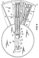
- Fig. 6 shows one way in which a variety of dental tools might be packed or loaded into the tool holder described above, to provide such a simple, compact dental tool kit.
- a number of dental posts 60 is shown loaded into one of the primary tool-storage compartments 18. Other compartments 18 can be similarly filled or charged.
- the dental posts are depicted as torpedo-shaped with a generally rounded or circular cross-section.
- At least two dental post wrenches 62 can be accommodated in the secondary compartment 26.
- These wrenches 62 comprise a hollow drum 64 at one end of the wrench, defining a socket designed and sized to mate with the head of a dental post 60; the cavity 68 is a close fit to a dental post 60, so as to be able to grip it.
- the other end of the post wrench 62 has outwardly extending fins 70, preferably three, to enable it to be turned manually.
- Two or more post wrenches 62 can be stowed end-for-end in the secondary compartment 26, the socket end of one wrench nesting between the fins 70 of another; which effect is enhanced for post wrenches 62 having three fins 70.
- Fig. 6 read with Fig. 4 shows that, for example, up to nine reamers 72 can be stowed in the reamer compartment 28 and, noting that the attached figures are drawn approximately in proportion, the reamers 72 are too long to fit in either a primary compartment 18 or a secondary compartment 26.
- the reamers 72 are elongated, having a holder portion at one end for attachment to a dental drill handpiece, and a tapered operating end point 76, at the second end.
- a useful feature of this invention is that by providing for the primary opening 48, which is used to access the reamer compartment 28, to be shorter than a typical reamer 72, the reamers 72 can naturally be stowed with all their points 76 inwards, beneath the lid 12, reducing the chance of a dentist or technician pricking their finger while extracting a reamer 72 from the dental tool container. Such minor wounds are greatly to be avoided in the dental environment as they offer a potentially dangerous route of infection.
- a dental tool kit comprising the container and tools as described and shown, is compact and economical without sacrificing utility, and the container is uniquely designed to satisfy the requirements of both distribution and use with a minimum of parts.
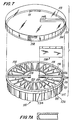
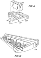
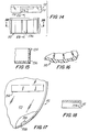
- FIG. 7 through 18 Other embodiments of the dental tool container and kit in accordance with the present invention are shown by Figs. 7 through 18. As shown by these drawings, there are several primary modifications to the first embodiment, and several alternative minor changes within the changed broader concept.
- the internal width of these compartments is preferably no greater than the minimum width of the remaining wedge-shaped primary compartments, generally designated as 118.
- the central portion 120 within the inner circumferential wall 122, is otherwise covered by a plate 120, upon which can be secured a label or other material imprinted directly onto the wall surface 120.
- One of the elongated rectangular chambers 128 is designed to hold the relatively longer reamer tools, and is thus designated the reamer compartment 128.
- the second elongated rectangular compartment 139 is designed to hold the gauge block 136.
- the remaining twenty-two (22) primary storage compartments 118 are each separated by relatively thin side walls 116, which extend substantially along radii of the cylindrical container between the outer circumferential wall 115d and the inner circumferential wall 122. These primary compartments, each generally indicated by the numeral 118, are thus each substantially segments of a cylinder. At least one of these primary compartments 118 is identified as a stop holder compartment 119, and is provided with perforated platform 117. The purpose of the platform is explained below.
- An outwardly extending flange 134 is formed on the upper portion of the outer circumferential wall 114.
- Indexing grooves 136 extend longitudinally along the outer circumferential wall, from the flange 134 to the bottom of the container 10.
- a substantially radially extending measuring groove 179 is formed along the top surface of the compartment wall separating the gauge block compartment 139 from the adjacent stops compartment 119. This measuring groove 179 extends from the upper lip 134 radially inwardly, alongside the gauge block compartment, generally measuring at least about thirty-five (35) millimeters in length.
- the clear lid 112 for this container of the second embodiment is also formed of substantially transparent plastic and is generally cylindrical in shape, having a circular top 113 and a circumferential skirt 144, dependent from the top.
- the lid 112 has a single primary opening 148 in the shape substantially of a rectangle extending towards the center of the lid substantially from the outer rim 144.
- the opening 148 is so shaped as to be registrable with and to extend substantially the same length as the reamer compartment 128, but preferably should not extend up to the center of the lid.
- the gauge block 138, and its block compartment 139 are not longer than the reamer tool compartment 128.
- the removable locking pin and tab 50 are replaced by a permanent indexing ratchet system, comprising an indexing pawl 158 and the index slots 115.
- the indexing pawl 158 is flexibly connected to the lid side wall 111, but as is shown in the drawings, the indexing pawl 158 can be formed integral with the lid, but of a flexible material.
- the indexing pawl 158 is designed to fit within the indexing grooves or slots 136 along the outer surface of the container 110, and to fit under the flange 134, so as to engage the bottom surface of the flange 134 with the upper surface of the ratchet pawl 158.
- a partial reentrant lip 111 is secured to and extends inwardly from the inner surface of the lid skirt 144, at a location substantially 180 from the ratchet pawl 158.
- the reentrant lip 111 is located on the lid skirt 111 so as to fit under and to contact the bottom surface of, the container flange 134.
- the lid 112 is thus held in place on the container 110 by the interaction between the reentrant lip 111 on one side of the lid and the top surface 159 of the pawl 158 on the other side of the lid 112, and the bottom surface of the flange 134.
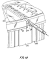
- a concave side slot defined by curved surface 177 is located slightly offset from the access opening 148 in the lid and extends through the lid skirt 111.
- the side slot 177 and the tool opening 148 are so juxtaposed that when the opening 148 is registered above the gauge block 138, the lid slot 177 registers with the measuring groove 179 along the container top surface. Further, when the latter items are in register, one with the other, the indexing ratchet pawl 158 registers with one of the indexing ratchet slots 136.
- the container is originally supplied to a dentist with the tool opening 148 closed off by a breakaway covering sheet 150, secured to the lid.
- the covering sheet substantially prevents any of the tools stored in any of the compartments from falling out of the container, even if the container is overturned and regardless of the rotational position of the lid 112. It is thus not necessary to lock the lid in any particular rotational position. It has been found, that during actual use by a dentist, the indexing ratchet is sufficient to maintain a desired rotational position of a lid while removing a desired tool, or when not in use to retain the lid in the position where the opening 148 is registered over the measuring gauge block 138.
- the measuring gauge compartment and the reamer compartment are shown 180 apart, these locations can be spaced more closely, as long as there is sufficient distance to avoid intersection of the two compartments. Thus, in most situations, these items can be anywhere from 60 to 180 displaced.
- the measuring groove is shown immediately adjacent the gauge block compartment, thus permitting measuring both the diameter, or gauge, of the reamer and measuring the length of the reamer without moving the lid.
- the stop compartment 119 By placing the stop compartment 119 immediately adjacent the gauge block, the rotation of the lid once the stop has been engaged on the reamer is reduced to a minimum.
- the indexing pawl 158 is located about 60 of rotation away from the opening 148 and slot 177.
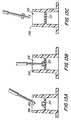
- the presence of the perforated platform 117 in the stop compartment 119 significantly eases placing, or impaling, the stop onto a reamer.
- the perforated platform 117 which can be wedged within the compartment, or can stand above a lower floor, permits the reamer to extend through the stop and into the floor, thus enabling the stop to be impaled and easily withdrawn from the compartment, as shown in Figs. 13a-c.
- the longitudinal measuring gauge marks are formed on the top surface of the container, on the top surface of the wall separating the groove 179 from the gauge block compartment 139.
- the measuring marks can be formed on the lid top 113, as is shown in Fig. 10.
- the gauge marks are formed radially inwardly from the lid slot 177, such that when the lid slot is in registry with the measuring groove 179, the measuring marks extend across and above the measuring groove 179.
- the measuring marks can be formed along the gauge block 138.
- the container has a substantially continuous bottom surface wall 130 forming a floor for all of the compartments.
- the container of this invention is not limited to any particular size or contents, and can be adapted for storing a variety of tools or other articles. However for the particular dentistry purposes described, the container is conveniently of a size to be held in the hand, for example from two to six inches across.
- a preferred embodiment for storing and dispensing the tools described is a little over three inches in diameter, across the selector lid 12, and has twenty-two (22) primary compartments 18 that are about three-quarters of an inch long, and a reamer compartment 26 that is a little over an inch long, with a depth of about three-eighths of an inch for the primary compartments 18.
- the perforated platform 117 in the stop compartment 119 can be press fit in place above the floor, or it can rest on legs, not shown, supported by the floor 130.
Landscapes
- Health & Medical Sciences (AREA)
- Veterinary Medicine (AREA)
- General Health & Medical Sciences (AREA)
- Engineering & Computer Science (AREA)
- Public Health (AREA)
- Life Sciences & Earth Sciences (AREA)
- Dentistry (AREA)
- Animal Behavior & Ethology (AREA)
- Oral & Maxillofacial Surgery (AREA)
- Epidemiology (AREA)
- Nuclear Medicine, Radiotherapy & Molecular Imaging (AREA)
- Mechanical Engineering (AREA)
- Surgery (AREA)
- Neurosurgery (AREA)
- Neurology (AREA)
- Biomedical Technology (AREA)
- Dental Tools And Instruments Or Auxiliary Dental Instruments (AREA)
- Cosmetics (AREA)
- Packaging Of Annular Or Rod-Shaped Articles, Wearing Apparel, Cassettes, Or The Like (AREA)
- Milling, Broaching, Filing, Reaming, And Others (AREA)
- Dental Prosthetics (AREA)
Claims (21)
- Ein Behälter für zahnärztliche Werkzeuge, umfassend: einen ringförmigen Werkzeughalter; eine Mehrzahl von primären Werkzeugaufbewahrungsfächern (18) für Zahnwurzelstifte, wobei die besagten Fächer rings um den Werkzeughalter angeordnet sind; einen auf dem Werkzeughalter drehbar angeordneten Selektionsdeckel (12), der die Fächer abdeckt; eine primäre Öffnung (48) in dem Selektionsdeckel zwecks Zugriff zu den besagten primären Fächern; wobei Drehung des Selektionsdeckels (12) die besagte primäre Öffnung (48) mit jedem primären Fach (18) der Reihe nach zur Deckung bringen kann, so daß Zugriff zu dem besagten Fach möglich ist; dadurch gekennzeichnet, daß der Werkzeugbehälter des weiteren folgende Teile umfaßt: ein sekundäres Werkzeugaufbewahrungsfach (26) für Zahnwurzelstiftschlüssel, wobei das besagte sekundäre Fach im Verhältnis zu dem Werkzeughalter mittig angeordnet und durch die besagten primären Fächer (18) umgeben ist; und eine sekundäre Öffnung (58) in dem Selektionsdeckel (12) zwecks Zugriff zu dem besagten sekundären Fach (26); wobei Drehung des auf dem Werkzeughalter befindlichen Selektionsdeckels die darin vorgesehene sekundäre Öffnung mit dem besagten sekundären Fach zwecks Zugriff zur Deckung bringen bzw. die Deckung aufheben kann; sowie dadurch, daß mindestens eines der besagten primären Fächer (28) verlängert ist, so daß es sich über die anderen der besagten primären Fächer (18) hinaus auf die Mitte zu erstreckt, um zwecks Aufnahme von Reibahlen ein Reibahlenfach zu bilden.
- Ein Behälter für zahnärztliche Werkzeuge nach Anspruch 1, bei dem sich das sekundäre Fach (26) quer über den Werkzeughalter erstreckt, so daß es an das Reibahlenfach (28) angrenzt.
- Ein Behälter für zahnärztliche Werkzeuge nach Anspruch 1 oder 2, bei dem der Werkzeughalter im allgemeinen zylindrisch ist und eine Außenwand mit kreisförmigem Querschnitt aufweist und die primären Werkzeugaufbewahrungsfächer (18) keilförmig sind.
- Ein Behälter für zahnärztliche Werkzeuge nach Anspruch 3, bei dem der Werkzeughalter des weiteren einen Boden (30) umfaßt, der sich unterhalb der primären und sekundären Fächer und zwischen den besagten Fächern kontinuierlich erstreckt.
- Ein Behälter für zahnärztliche Werkzeuge nach Anspruch 1 mit einem Abreißansatz (50) zum Sperren des Selektionsdeckels (12) in einer für den Vertrieb geschlossenen Lage.
- Ein Behälter für zahnärztliche Werkzeuge nach Anspruch 1 mit einem Meßblock (38) in einem der primären Fächer (18), wobei der besagte Block zum Messen von in anderen der besagten Fächer aufzubewahrenden Werkzeugen geeignet ist.
- Ein Behälter für zahnärztliche Werkzeuge nach Anspruch 6 mit einem Abreißansatz (50) zum Sperren des Selektionsdeckels in einer für den Vertrieb geschlossenen Lage, wobei der besagte Abreißansatz so beschaffen ist, daß er in den Meßblock eingreift, um den Selektionsdeckel (12) dadurch gegen Drehung zu sperren und den Meßblock in dem dafür bestimmten primären Fach zu halten.
- Eine Ausrüstung für zahnärztliche Werkzeuge umfassend einen Behälter für zahnärztliche Werkzeuge nach Anspruch 1 und mindestens drei verschiedene, in dessen Fächer eingelegte Werkzeuge.
- Eine Ausrüstung für zahnärztliche Werkzeuge nach Anspruch 8, bei der Zahnwurzelstifte und ein Meßblock in den primären Fächern des Werkzeughalters aufbewahrt werden, Reibahlen in einem verlängerten Reibahlenfach aufbewahrt werden und einer oder mehrere Zahnwurzelstiftschlüssel in dem sekundären Fach aufbewahrt wird/werden.
- Ein Behälter für zahnärztliche Werkzeuge nach Anspruch 1, bei dem innerhalb eines der besagten primären Fächer (18) und sich völlig quer dazu erstreckend zwecks Aufbewahrung von zahnärztlichen Reibahlenanschlägen eine gelochte Plattform (117) vorgesehen ist, wobei die durch die Plattform hindurchführenden Öffnungen klein genug sind, um den Durchgang eines Anschlags zu verhindern, aber genügend groß sind, um mindestens den Endspitzenbereich einer Reibahle aufzunehmen; und bei dem innerhalb eines der besagten primären Fächer ein Meßblock (38) enthalten ist, der zum Messen des Kalibers von in den anderen Fächern aufzubewahrenden Werkzeugen bestimmt ist; während Drehung des Selektionsdeckels (12) auf dem Werkzeughalter, die in dem besagten Selektionsdeckel befindliche primäre Öffnung mit jedem der besagten primären Fächer zwecks Zugriff zu einem Werkzeug oder mit dem Meßblock zum Messen des Durchmessers eines Werkzeugs zur Deckung gebracht bzw. die Deckung aufgehoben werden kann.
- Ein Behälter für zahnärztliche Werkzeuge nach Anspruch 10, bei dem das verlängerte primäre Fach (28) im wesentlichen parallele Seiten aufweist.
- Ein Behälter für zahnärztliche Werkzeuge nach Anspruch 11, bei dem ein zweites primäres Fach (139) verlängert ist, so daß es sich einwärts auf die Mitte zu durch die innere periphere Wand hindurch und über diese hinaus erstreckt, und bei dem der Meßblock (136) im Paßsitz in dieses zweite verlängerte primäre Fach hineinpaßt.
- Ein Behälter für zahnärztliche Werkzeuge nach Anspruch 12, bei dem der Werkzeughalter im allgemeinen kreisförmig ist und eine Außenwand von kreisförmigem Querschnitt aufweist, und bei dem mindestens die meisten primären Werkzeugaufbewahrungsfächer (18) im Grundriß keilstumpfförmig sind.
- Ein Behälter für zahnärztliche Werkzeuge nach Anspruch 11, umfassend eine dicker ausgeführte Trennwand zwischen dem Meßblockfach und dem anschließenden primären Fach, wobei die besagte Trennwand eine obere Oberfläche, eine in und entlang der oberen Oberfläche geformte Meßnut (179), die sich von der äußeren peripheren Wand und durch diese hindurch einwärts erstreckt, sowie Meßmarkenmittel zum Messen der Länge eines innerhalb der Meßnut befindlichen Werkzeugs aufweist.
- Ein Behälter für zahnärztliche Werkzeuge nach Anspruch 11, bei dem der Deckel eine obere Oberfläche umfaßt, durch die sich die primäre Öffnung hindurch erstreckt, sowie einen peripheren Randbereich, der sich quer zu der oberen Oberfläche erstreckt und mindestens einen Teil der äußeren Wand des Werkzeughalters umgibt, wobei mindestens ein durch den Rand hindurchführender Werkzeugschlitz geformt ist, der die Aufgabe hat, den Durchgang eines Werkzeugs in die Meßnut zu gestatten, wenn der Deckel so angeordnet ist, daß sich der Werkzeugschlitz mit der Meßnut in Deckung befindet.
- Ein Behälter für zahnärztliche Werkzeuge nach Anspruch 15, der des weiteren ein zwischen dem Deckel und dem Behälter angebrachtes Fortschaltmittel (158) umfaßt, das gewährleistet, daß bei jedem stabilen Verhältnis zwischen der Winkellage des Behälters und des Deckels die Primäröffnung (48) mit einem primären Fach (18) zur Deckung gebracht wird.
- Ein Behälter für zahnärztliche Werkzeuge nach Anspruch 16, bei dem das Schaltmittel (158) eine flexibel an dem Deckel angebrachte Klinke und entlang der äußeren peripheren Wand des Behälters geformte Schaltschlitze (136) umfaßt.
- Ein Behälter für zahnärztliche Werkzeuge nach Anspruch 11 mit einem Abreißansatz (50) zum Abdichten der primären Öffnung in dem Deckel.
- Eine Ausrüstung für zahnärztliche Werkzeuge, umfassend einen Behälter für zahnärztliche Werkzeuge nach Anspruch 11 und mindestens drei verschiedene Werkzeuge, Anschlagringe und einen Meßblock, die in die Fächer des besagten Behälters eingelegt sind.
- Ein Behälter für zahnärztliche Werkzeuge nach Anspruch 1, bei dem innerhalb eines der besagten primären Fächer ein Meßblock (38) angeordnet ist; und innerhalb eines zweiten der besagten primären Fächer eine gelochte Plattform (117) vorgesehen ist und sich quer zu dem besagten zweiten der besagten primären Fächer erstreckt, wobei in dem besagten zweiten primären Fach (28) die zahnärztlichen Reibahlenanschläge vorgesehen sind.
- Ein Behälter für zahnärztliche Werkzeuge nach Anspruch 1, bei dem sich zwecks Aufbewahrung von zahnärztlichen Reibahlenanschlägen eine gelochte Plattform (117) innerhalb eines der besagten primären Werkzeugaufbewahrungsfächer befindet und sich völlig quer dazu erstreckt, wobei die durch die Plattform führenden Öffnungen klein genug sind, um den Durchgang eines Reibahlenanschlags zu verhindern, aber groß genug sind, um mindestens den Endspitzenbereich einer Reibahle aufzunehmen; und die gelochte Plattform (117) sich entlang einer Ebene erstreckt, die von dem Selektionsdeckel genügend weit entfernt ist, um die Unterbringung von Reibahlenanschlägen in dem Fach zu gestatten, ohne daß die Drehung des Deckels (12) dadurch behindert wird.
Applications Claiming Priority (3)
| Application Number | Priority Date | Filing Date | Title |
|---|---|---|---|
| US07/678,785 US5150788A (en) | 1991-04-01 | 1991-04-01 | Reamer/wrench/post kit |
| US678785 | 1991-04-01 | ||
| PCT/US1992/002607 WO1992017389A1 (en) | 1991-04-01 | 1992-03-31 | Reamer/wrench/post kit |
Publications (3)
| Publication Number | Publication Date |
|---|---|
| EP0578778A1 EP0578778A1 (de) | 1994-01-19 |
| EP0578778A4 EP0578778A4 (de) | 1994-02-02 |
| EP0578778B1 true EP0578778B1 (de) | 1997-01-29 |
Family
ID=24724259
Family Applications (1)
| Application Number | Title | Priority Date | Filing Date |
|---|---|---|---|
| EP92911294A Expired - Lifetime EP0578778B1 (de) | 1991-04-01 | 1992-03-31 | Behälter für reibahle/schlüssel/zahnwurzelstift |
Country Status (9)
| Country | Link |
|---|---|
| US (1) | US5150788A (de) |
| EP (1) | EP0578778B1 (de) |
| JP (1) | JP3390432B2 (de) |
| AT (1) | ATE148422T1 (de) |
| AU (1) | AU1919692A (de) |
| CA (1) | CA2106783C (de) |
| DE (1) | DE69217213T2 (de) |
| ES (1) | ES2099258T3 (de) |
| WO (1) | WO1992017389A1 (de) |
Cited By (1)
| Publication number | Priority date | Publication date | Assignee | Title |
|---|---|---|---|---|
| DE102005030553A1 (de) * | 2005-06-22 | 2006-12-28 | Aesculap Ag & Co. Kg | Chirurgischer Schraubenbehälter |
Families Citing this family (29)
| Publication number | Priority date | Publication date | Assignee | Title |
|---|---|---|---|---|
| US5465556A (en) * | 1993-08-02 | 1995-11-14 | Avid Marketing, Inc. | Container providing selective access to stored objects |
| US5595296A (en) * | 1995-02-14 | 1997-01-21 | Poly Vac, Incorporated | Sterilization and storage container |
| US5590774A (en) * | 1995-06-06 | 1997-01-07 | Roberts; Holly H. | Surgical needle discard container |
| IT1278836B1 (it) * | 1995-06-06 | 1997-11-28 | Orthofix Srl | Contenitore multifunzionale particolarmente per fili filettati per operazioni di chirurgia ortopedica |
| US5958338A (en) * | 1997-10-31 | 1999-09-28 | Terumo Cardiovascular Systems Corporation | Mounting apparatus for blood handling systems |
| AU2001272375A1 (en) * | 2000-08-03 | 2002-02-18 | Novo-Nordisk A/S | A needle magazine |
| US6451023B1 (en) * | 2001-01-25 | 2002-09-17 | Linvatec Corporation | Guide bushing for coring reamer, storage package for reamer assembly, and method of use |
| US6681925B2 (en) | 2001-12-19 | 2004-01-27 | Ultradent Products, Inc. | Autoclavable and resealable endo file container |
| WO2005089370A2 (en) | 2004-03-16 | 2005-09-29 | Goodis Charles J | Endodontic files and obturator devices and methods of manufacturing same |
| US20060228676A1 (en) * | 2005-03-31 | 2006-10-12 | Brown Phillip L | Dental post analogs |
| US7195485B2 (en) * | 2005-04-01 | 2007-03-27 | Ultradent Products, Inc. | Kits for placement of a dental post |
| US7278852B2 (en) * | 2005-04-01 | 2007-10-09 | Ultradent Products, Inc. | Kit of sub-kits for placing a dental post |
| US20070142254A1 (en) * | 2005-12-02 | 2007-06-21 | Sandra Arce | Storage system |
| US20070129269A1 (en) * | 2005-12-02 | 2007-06-07 | Sandra Arce | Storage system |
| GB0808158D0 (en) * | 2008-05-06 | 2008-06-11 | Harrison Nicholas | Needle dispenser |
| ITCR20090038A1 (it) * | 2009-09-18 | 2011-03-19 | Preda Piergiuseppe | Dispositivo contenitore per strumenti odontoiatrici canalari tipo m2 |
| FR2951632B1 (fr) * | 2009-10-23 | 2011-11-25 | Apol | Dispositif de stockage et de distribution de pieces destinees a l'art dentaire |
| JP2012029977A (ja) * | 2010-08-02 | 2012-02-16 | Gc Corp | ストッパ収納ケース |
| US9381303B2 (en) | 2010-08-16 | 2016-07-05 | Becton, Dickinson And Company | Sterility barrier for pen needle and storage container therefor |
| JP5616168B2 (ja) * | 2010-08-31 | 2014-10-29 | マニー株式会社 | 包装された歯科用回転治療器具 |
| US8919555B2 (en) | 2010-09-01 | 2014-12-30 | Sambhu N. Choudhury | Medical sharps storage device and method of using the same |
| US8739444B2 (en) * | 2011-03-08 | 2014-06-03 | Ronnie Poole | Color coding system for sizing fastener parts, tools and storage bins |
| KR101340006B1 (ko) | 2011-12-01 | 2013-12-10 | 주식회사 세라젬메디시스 | 분석장치의 저장용기 |
| US8727118B1 (en) * | 2012-12-18 | 2014-05-20 | Chao-Ming Chen | Rotary tool box |
| DE102014003398B4 (de) * | 2014-03-10 | 2016-01-21 | András Csögör | Zahnmedizinische Vorrichtung |
| AU201612256S (en) * | 2015-11-02 | 2016-07-07 | P C O A Devices Ltd | Medications Dispensing Apparatus |
| AU201612257S (en) * | 2015-11-02 | 2016-07-07 | P C O A Devices Ltd | Medications Dispensing Apparatus |
| DE102018126242B4 (de) * | 2018-10-22 | 2025-11-06 | Eberhard Karls Universität Tübingen Medizinische Fakultät | Abstandshalter für ein endodontisches Instrument |
| US20220048693A1 (en) * | 2020-08-13 | 2022-02-17 | Ferrara Candy Company | Confection dispenser system |
Family Cites Families (11)
| Publication number | Priority date | Publication date | Assignee | Title |
|---|---|---|---|---|
| CA557226A (en) * | 1958-05-13 | C. Tornberg Gordon | Medicinal tablet container and dispenser | |
| US2148721A (en) * | 1937-10-01 | 1939-02-28 | Avstreih William | Burr holding device |
| GB606159A (en) * | 1940-05-30 | 1948-08-06 | A Sengelin & Lucior Ets | Improvements in distributors or containers for small objects |
| US2780349A (en) * | 1954-09-20 | 1957-02-05 | Gordon C Tornberg | Medicinal tablet container and dispenser |
| US3394796A (en) * | 1967-07-25 | 1968-07-30 | Warren R. Jensen | Pill dispenser |
| DE2133091C3 (de) * | 1971-07-02 | 1973-11-29 | Willi 5910 Kreuztal Otto | Kleinbehälter fur Pillen od dgl |
| US3926335A (en) * | 1974-03-18 | 1975-12-16 | Thomas C Dangles | Capsule or pill dispenser-sure way dial a pill |
| US4288006A (en) * | 1975-10-20 | 1981-09-08 | Dale J. Kirstine | Multi-compartment container |
| CA1085352A (en) * | 1978-09-19 | 1980-09-09 | William Rossmo | Medication dispenser |
| US4449630A (en) * | 1982-01-18 | 1984-05-22 | Filhol Stuart J | Package for dental tools |
| US4399914A (en) * | 1982-04-16 | 1983-08-23 | Triad Corporation | Pilfer resistant container |
-
1991
- 1991-04-01 US US07/678,785 patent/US5150788A/en not_active Expired - Lifetime
-
1992
- 1992-03-31 AU AU19196/92A patent/AU1919692A/en not_active Abandoned
- 1992-03-31 EP EP92911294A patent/EP0578778B1/de not_active Expired - Lifetime
- 1992-03-31 ES ES92911294T patent/ES2099258T3/es not_active Expired - Lifetime
- 1992-03-31 WO PCT/US1992/002607 patent/WO1992017389A1/en not_active Ceased
- 1992-03-31 AT AT92911294T patent/ATE148422T1/de not_active IP Right Cessation
- 1992-03-31 JP JP51063092A patent/JP3390432B2/ja not_active Expired - Fee Related
- 1992-03-31 DE DE69217213T patent/DE69217213T2/de not_active Expired - Fee Related
- 1992-03-31 CA CA002106783A patent/CA2106783C/en not_active Expired - Fee Related
Cited By (1)
| Publication number | Priority date | Publication date | Assignee | Title |
|---|---|---|---|---|
| DE102005030553A1 (de) * | 2005-06-22 | 2006-12-28 | Aesculap Ag & Co. Kg | Chirurgischer Schraubenbehälter |
Also Published As
| Publication number | Publication date |
|---|---|
| DE69217213D1 (de) | 1997-03-13 |
| EP0578778A1 (de) | 1994-01-19 |
| EP0578778A4 (de) | 1994-02-02 |
| CA2106783A1 (en) | 1992-10-02 |
| WO1992017389A1 (en) | 1992-10-15 |
| DE69217213T2 (de) | 1997-07-17 |
| AU1919692A (en) | 1992-11-02 |
| ES2099258T3 (es) | 1997-05-16 |
| ATE148422T1 (de) | 1997-02-15 |
| JPH06506427A (ja) | 1994-07-21 |
| CA2106783C (en) | 2003-03-11 |
| JP3390432B2 (ja) | 2003-03-24 |
| US5150788A (en) | 1992-09-29 |
Similar Documents
| Publication | Publication Date | Title |
|---|---|---|
| US5150788A (en) | Reamer/wrench/post kit | |
| EP2173487B1 (de) | Probenbehälterausrüstungen mit einweg-einsätzen | |
| US5238140A (en) | Medication storage and dispensing device | |
| US5186329A (en) | Portable tool holder | |
| US5806670A (en) | Portable multipurpose pill box container | |
| US5525314A (en) | Surgical tool container system | |
| US4475654A (en) | Storage and individualized dosage container | |
| US5540329A (en) | Bucket-inserted hardware organizer | |
| US4763791A (en) | Dental impression supply kit | |
| US4483440A (en) | Disposal device with display panels | |
| US4802438A (en) | Container collar dosage time indicator and container | |
| US5322166A (en) | Pill storage and dispensing container | |
| US4165709A (en) | Tablet dispenser | |
| US6000159A (en) | Datable food storage containers | |
| US4298125A (en) | Dial type child resistant dispenser | |
| US7857129B2 (en) | Container and carrier system for surgical auxiliary material | |
| US4333567A (en) | Plate for packaging dental root-canal instruments | |
| US20090127157A1 (en) | Pill bottle | |
| SE509074C2 (sv) | Behållare för lagring och uppläggning av varor | |
| US4289249A (en) | Container | |
| USRE33319E (en) | Dispenser for pasty compositions | |
| US4449630A (en) | Package for dental tools | |
| US4573571A (en) | Pencil case | |
| US4182040A (en) | Endodontic file holder and gauge | |
| US4203515A (en) | Dental cap package |
Legal Events
| Date | Code | Title | Description |
|---|---|---|---|
| PUAI | Public reference made under article 153(3) epc to a published international application that has entered the european phase |
Free format text: ORIGINAL CODE: 0009012 |
|
| 17P | Request for examination filed |
Effective date: 19931006 |
|
| AK | Designated contracting states |
Kind code of ref document: A1 Designated state(s): AT BE CH DE DK ES FR GB GR IT LI LU MC NL SE |
|
| A4 | Supplementary search report drawn up and despatched |
Effective date: 19931214 |
|
| AK | Designated contracting states |
Kind code of ref document: A4 Designated state(s): AT BE CH DE DK ES FR GB GR IT LI LU MC NL SE |
|
| 17Q | First examination report despatched |
Effective date: 19950905 |
|
| GRAG | Despatch of communication of intention to grant |
Free format text: ORIGINAL CODE: EPIDOS AGRA |
|
| GRAH | Despatch of communication of intention to grant a patent |
Free format text: ORIGINAL CODE: EPIDOS IGRA |
|
| GRAH | Despatch of communication of intention to grant a patent |
Free format text: ORIGINAL CODE: EPIDOS IGRA |
|
| GRAA | (expected) grant |
Free format text: ORIGINAL CODE: 0009210 |
|
| AK | Designated contracting states |
Kind code of ref document: B1 Designated state(s): AT BE CH DE DK ES FR GB GR IT LI LU MC NL SE |
|
| PG25 | Lapsed in a contracting state [announced via postgrant information from national office to epo] |
Ref country code: NL Free format text: LAPSE BECAUSE OF FAILURE TO SUBMIT A TRANSLATION OF THE DESCRIPTION OR TO PAY THE FEE WITHIN THE PRESCRIBED TIME-LIMIT Effective date: 19970129 Ref country code: GR Free format text: LAPSE BECAUSE OF FAILURE TO SUBMIT A TRANSLATION OF THE DESCRIPTION OR TO PAY THE FEE WITHIN THE PRESCRIBED TIME-LIMIT Effective date: 19970129 Ref country code: DK Effective date: 19970129 Ref country code: BE Effective date: 19970129 Ref country code: AT Effective date: 19970129 |
|
| REF | Corresponds to: |
Ref document number: 148422 Country of ref document: AT Date of ref document: 19970215 Kind code of ref document: T |
|
| REG | Reference to a national code |
Ref country code: CH Ref legal event code: EP |
|
| REF | Corresponds to: |
Ref document number: 69217213 Country of ref document: DE Date of ref document: 19970313 |
|
| REG | Reference to a national code |
Ref country code: CH Ref legal event code: NV Representative=s name: TROESCH SCHEIDEGGER WERNER AG |
|
| PG25 | Lapsed in a contracting state [announced via postgrant information from national office to epo] |
Ref country code: LU Free format text: LAPSE BECAUSE OF NON-PAYMENT OF DUE FEES Effective date: 19970331 |
|
| ITF | It: translation for a ep patent filed | ||
| REG | Reference to a national code |
Ref country code: ES Ref legal event code: FG2A Ref document number: 2099258 Country of ref document: ES Kind code of ref document: T3 |
|
| ET | Fr: translation filed | ||
| NLV1 | Nl: lapsed or annulled due to failure to fulfill the requirements of art. 29p and 29m of the patents act | ||
| PG25 | Lapsed in a contracting state [announced via postgrant information from national office to epo] |
Ref country code: MC Effective date: 19970930 |
|
| PLBE | No opposition filed within time limit |
Free format text: ORIGINAL CODE: 0009261 |
|
| STAA | Information on the status of an ep patent application or granted ep patent |
Free format text: STATUS: NO OPPOSITION FILED WITHIN TIME LIMIT |
|
| 26N | No opposition filed | ||
| PGFP | Annual fee paid to national office [announced via postgrant information from national office to epo] |
Ref country code: SE Payment date: 20000329 Year of fee payment: 9 |
|
| PGFP | Annual fee paid to national office [announced via postgrant information from national office to epo] |
Ref country code: ES Payment date: 20000331 Year of fee payment: 9 |
|
| PGFP | Annual fee paid to national office [announced via postgrant information from national office to epo] |
Ref country code: DE Payment date: 20000403 Year of fee payment: 9 |
|
| PGFP | Annual fee paid to national office [announced via postgrant information from national office to epo] |
Ref country code: GB Payment date: 20000405 Year of fee payment: 9 |
|
| PGFP | Annual fee paid to national office [announced via postgrant information from national office to epo] |
Ref country code: FR Payment date: 20000411 Year of fee payment: 9 |
|
| PGFP | Annual fee paid to national office [announced via postgrant information from national office to epo] |
Ref country code: CH Payment date: 20000414 Year of fee payment: 9 |
|
| PG25 | Lapsed in a contracting state [announced via postgrant information from national office to epo] |
Ref country code: LI Free format text: LAPSE BECAUSE OF NON-PAYMENT OF DUE FEES Effective date: 20010331 Ref country code: GB Free format text: LAPSE BECAUSE OF NON-PAYMENT OF DUE FEES Effective date: 20010331 Ref country code: CH Free format text: LAPSE BECAUSE OF NON-PAYMENT OF DUE FEES Effective date: 20010331 |
|
| PG25 | Lapsed in a contracting state [announced via postgrant information from national office to epo] |
Ref country code: SE Free format text: LAPSE BECAUSE OF NON-PAYMENT OF DUE FEES Effective date: 20010401 |
|
| PG25 | Lapsed in a contracting state [announced via postgrant information from national office to epo] |
Ref country code: ES Free format text: LAPSE BECAUSE OF NON-PAYMENT OF DUE FEES Effective date: 20010402 |
|
| REG | Reference to a national code |
Ref country code: CH Ref legal event code: PL |
|
| GBPC | Gb: european patent ceased through non-payment of renewal fee |
Effective date: 20010331 |
|
| PG25 | Lapsed in a contracting state [announced via postgrant information from national office to epo] |
Ref country code: FR Free format text: LAPSE BECAUSE OF NON-PAYMENT OF DUE FEES Effective date: 20011130 |
|
| EUG | Se: european patent has lapsed |
Ref document number: 92911294.4 |
|
| REG | Reference to a national code |
Ref country code: FR Ref legal event code: ST |
|
| PG25 | Lapsed in a contracting state [announced via postgrant information from national office to epo] |
Ref country code: DE Free format text: LAPSE BECAUSE OF NON-PAYMENT OF DUE FEES Effective date: 20020101 |
|
| REG | Reference to a national code |
Ref country code: ES Ref legal event code: FD2A Effective date: 20030303 |
|
| PG25 | Lapsed in a contracting state [announced via postgrant information from national office to epo] |
Ref country code: IT Free format text: LAPSE BECAUSE OF NON-PAYMENT OF DUE FEES;WARNING: LAPSES OF ITALIAN PATENTS WITH EFFECTIVE DATE BEFORE 2007 MAY HAVE OCCURRED AT ANY TIME BEFORE 2007. THE CORRECT EFFECTIVE DATE MAY BE DIFFERENT FROM THE ONE RECORDED. Effective date: 20050331 |