EP0578401B1 - FCC-Regenerierungsverfahren und Vorrichtung zur Reduktion von NOX - Google Patents
FCC-Regenerierungsverfahren und Vorrichtung zur Reduktion von NOX Download PDFInfo
- Publication number
- EP0578401B1 EP0578401B1 EP93304812A EP93304812A EP0578401B1 EP 0578401 B1 EP0578401 B1 EP 0578401B1 EP 93304812 A EP93304812 A EP 93304812A EP 93304812 A EP93304812 A EP 93304812A EP 0578401 B1 EP0578401 B1 EP 0578401B1
- Authority
- EP
- European Patent Office
- Prior art keywords
- regenerator
- catalyst
- flue gas
- ppm
- fcc
- Prior art date
- Legal status (The legal status is an assumption and is not a legal conclusion. Google has not performed a legal analysis and makes no representation as to the accuracy of the status listed.)
- Expired - Lifetime
Links
Images

Classifications
-
- B—PERFORMING OPERATIONS; TRANSPORTING
- B01—PHYSICAL OR CHEMICAL PROCESSES OR APPARATUS IN GENERAL
- B01J—CHEMICAL OR PHYSICAL PROCESSES, e.g. CATALYSIS OR COLLOID CHEMISTRY; THEIR RELEVANT APPARATUS
- B01J38/00—Regeneration or reactivation of catalysts, in general
- B01J38/04—Gas or vapour treating; Treating by using liquids vaporisable upon contacting spent catalyst
- B01J38/12—Treating with free oxygen-containing gas
- B01J38/30—Treating with free oxygen-containing gas in gaseous suspension, e.g. fluidised bed
- B01J38/36—Treating with free oxygen-containing gas in gaseous suspension, e.g. fluidised bed and with substantially complete oxidation of carbon monoxide to carbon dioxide within regeneration zone
-
- C—CHEMISTRY; METALLURGY
- C10—PETROLEUM, GAS OR COKE INDUSTRIES; TECHNICAL GASES CONTAINING CARBON MONOXIDE; FUELS; LUBRICANTS; PEAT
- C10G—CRACKING HYDROCARBON OILS; PRODUCTION OF LIQUID HYDROCARBON MIXTURES, e.g. BY DESTRUCTIVE HYDROGENATION, OLIGOMERISATION, POLYMERISATION; RECOVERY OF HYDROCARBON OILS FROM OIL-SHALE, OIL-SAND, OR GASES; REFINING MIXTURES MAINLY CONSISTING OF HYDROCARBONS; REFORMING OF NAPHTHA; MINERAL WAXES
- C10G11/00—Catalytic cracking, in the absence of hydrogen, of hydrocarbon oils
- C10G11/14—Catalytic cracking, in the absence of hydrogen, of hydrocarbon oils with preheated moving solid catalysts
- C10G11/18—Catalytic cracking, in the absence of hydrogen, of hydrocarbon oils with preheated moving solid catalysts according to the "fluidised-bed" technique
- C10G11/182—Regeneration
-
- C—CHEMISTRY; METALLURGY
- C10—PETROLEUM, GAS OR COKE INDUSTRIES; TECHNICAL GASES CONTAINING CARBON MONOXIDE; FUELS; LUBRICANTS; PEAT
- C10G—CRACKING HYDROCARBON OILS; PRODUCTION OF LIQUID HYDROCARBON MIXTURES, e.g. BY DESTRUCTIVE HYDROGENATION, OLIGOMERISATION, POLYMERISATION; RECOVERY OF HYDROCARBON OILS FROM OIL-SHALE, OIL-SAND, OR GASES; REFINING MIXTURES MAINLY CONSISTING OF HYDROCARBONS; REFORMING OF NAPHTHA; MINERAL WAXES
- C10G11/00—Catalytic cracking, in the absence of hydrogen, of hydrocarbon oils
- C10G11/14—Catalytic cracking, in the absence of hydrogen, of hydrocarbon oils with preheated moving solid catalysts
- C10G11/18—Catalytic cracking, in the absence of hydrogen, of hydrocarbon oils with preheated moving solid catalysts according to the "fluidised-bed" technique
- C10G11/185—Energy recovery from regenerator effluent gases
Definitions
- the invention relates to regeneration of spent catalyst from an FCC unit in a way which reduces NO x emissions.
- NO x or oxides of nitrogen, in flue gas streams from FCC regenerators is a pervasive problem.
- FCC units process heavy feeds containing nitrogen compounds, and much of this material is eventually converted into NO x emissions, either in the FCC regenerator (if operated in full CO burn mode) or in a downstream CO boiler (if operated in partial CO burn mode).
- all FCC processing nitrogen containing feeds can have a NO x emissions problem due to catalyst regeneration, but the type of regeneration employed (full or partial CO burn mode) will determine whether NO x emissions appear sooner (regenerator flue gas) or later (CO boiler).
- Catalytic cracking of hydrocarbons is carried out in the absence of externally supplied H2, in contrast to hydrocracking, in which H2 is added during the cracking step.
- An inventory of particulate catalyst is continuously cycled between a cracking reactor and a catalyst regenerator.
- FCC fluidized catalytic cracking
- hydrocarbon feed contacts catalyst in a reactor at 425C-600°C, usually 460C-560°C.
- the hydrocarbons crack, and deposit carbonaceous hydrocarbons or coke on the catalyst.
- the cracked products are separated from the coked catalyst.
- the coked catalyst is stripped of volatiles, usually with steam, and is then regenerated.
- the coke is burned from the catalyst with oxygen-containing gas, usually air.
- Coke burns off, restoring catalyst activity and simultaneously heating the catalyst to, e.g., 500°C-900°C, usually 600°C-750°C.
- Flue gas formed by burning coke in the regenerator may be treated for removal of particulates and for conversion of carbon monoxide, after which the flue gas is normally discharged into the atmosphere.
- the high efficiency regenerator mixes recycled regenerated catalyst with spent catalyst, burns much of the coke from spent catalyst in a fast fluidized bed coke combustor, then discharges catalyst and flue gas up a dilute phase transport riser where some additional coke combustion occurs, and where most of the CO is afterburned to CO 2 .
- These regenerators are designed for complete CO combustion, and usually produce clean burned catalyst, and flue gas will very little CO, and modest amounts of NO x .
- the bubbling bed regenerator maintains the catalyst as a bubbling fluidized bed, to which spent catalyst is added and from which regenerated catalyst is removed.
- regenerators usually require more catalyst inventory in the regenerator, because gas/catalyst contacting is not so efficient in a bubbling fluidized bed as in a fast fluidized bed.
- bubbling bed regenerators operate in complete CO combustion mode, i.e., the mole ratio of CO 2 /CO is at least 10.
- Refiners try to burn CO completely within the catalyst regenerator to conserve heat and to minimize air pollution.
- ways suggested to decrease the amount of carbon on regenerated catalyst and to burn CO in the regenerator is to add a CO combustion promoter metal to the catalyst or to the regenerator.
- U.S. 4,072,600 and 4,093,535 teach use of combustion-promoting metals such as Pt, Pd, Ir, Rh, Os, Ru and Re in cracking catalysts in concentrations of 0.01 to 50 ppm, based on total catalyst inventory. This approach is so successful that most FCC units use Pt CO combustion promoter. This reduces CO emissions, but usually increases nitrogen oxides (NO x ) in the regenerator flue gas. It is difficult in a catalyst regenerator to burn completely coke and CO in the regenerator without increasing the NO x content of the regenerator flue gas. Many jurisdictions have passed legislation restricting the amount of NO x that can be in a flue gas stream discharged to the atmosphere. In response to environmental concerns, much effort has been spent on finding ways to reduce NO x emissions.
- combustion-promoting metals such as Pt, Pd, Ir, Rh, Os, Ru and Re in cracking catalysts in concentrations of 0.01 to 50 ppm, based on total catalyst inventory.
- NO x nitrogen oxides
- the NO x problem is most acute in bubbling dense bed regenerators, perhaps due to localized high oxygen concentrations in the large bubbles of regeneration air. Even the high efficiency regenerators, with better catalyst/gas contacting, produce significant amounts of NO x , though usually only about 50 - 75 % of the NO x which would be produced in a bubbling dense bed regenerator cracking a similar feed.
- U.S. 4,313,848 teaches countercurrent regeneration of spent FCC catalyst, without backmixing, to minimize NO x emissions.
- U.S. 4,309,309 teaches the addition of a vaporizable fuel to the upper portion of a FCC regenerator to minimize NO x emissions. Oxides of nitrogen formed in the lower portion of the regenerator are reduced in the reducing atmosphere generated by burning fuel in the upper portion of the regenerator.
- NO x emissions from an FCC unit were reduced by adding carbonaceous particles such as sponge coke or coal into the circulating inventory of cracking catalyst.
- the carbonaceous particles performed selectively absorbed metal contaminants in the feed and also reduced NO x emissions.
- Many refiners are reluctant to add coal or coke to their FCC units, and such materials also burn, and increase the heat release in the regenerator. Most refiners would prefer to reduce, rather than increase, heat release in their regenerators.
- Another process approach to reducing NO x emissions from FCC regenerators is to create a relatively reducing atmosphere in some portion of the regenerator by segregating the CO combustion promoter.
- Reduction of NO x emissions in FCC regenerators was achieved in U.S. 4,812,430 and 4,812,431 by using a conventional CO combustion promoter (Pt) on an unconventional support which permitted the support to segregate in the regenerator.
- Pt CO combustion promoter
- Use of large, hollow, floating spheres gave a sharp segregation of CO combustion promoter in the regenerator.
- the work that follows is generally directed at special catalysts which promote CO afterburning, but do not promote formation of much NO x .
- U.S. 4,300,997 and U.S. 4,350,615, are both directed to use of Pd-Ru CO-combustion promoter.
- the bi-metallic CO combustion promoter is reported to do an adequate job of converting CO to CO 2 , while minimizing the formation of NO x .
- U.S. 4,235,704 suggests too much CO combustion promoter causes NO x formation, and calls for monitoring the NO x content of the flue gases, and adjusting the concentration of CO combustion promoter in the regenerator based on the amount of NO x in the flue gas.
- the patentee suggests deactivating it in place, by adding something to deactivate the Pt, such as lead, antimony, arsenic, tin or bismuth.
- Such additives also add to the cost of the FCC process, may dilute the FCC equilibrium catalyst, and may not be as effective as desired.
- NH3 is a selective reducing agent, which does not react rapidly with the excess oxygen which may be present in the flue gas.
- Two types of NH3 process have evolved, thermal and catalytic.
- Thermal processes such as the Exxon Thermal DeNO x process, operate as homogeneous gas-phase processes at around 843 - 1038°C (1550-1900°F). More details of such a process are disclosed by Lyon, R. K., Int. J. Chem. Kinet., 3, 315, 1976, incorporated by reference.
- Catalytic systems have been developed which operate at lower temperatures, typically at 149 - 454°C (300-850°F). These temperatures are typical of flue gas streams. Unfortunately, the catalysts used in these processes are readily fouled, or the process lines plugged, by catalyst fines which are an integral part of FCC regenerator flue gas.
- U.S. 4,521,389 and 4,434,147 disclose adding NH3 to NO x -containing flue gas to reduce catalytically the NO x to nitrogen.
- Feed pretreatment is expensive, and can usually only be justified for sulfur removal. Segregated feed cracking helps significantly, but requires segregated high and low nitrogen feeds.
- the present invention provides a process for the catalytic cracking of nitrogen-containing hydrocarbon feed to lighter products as defined in claim 1.
- Apparatus suitable for the fluidized catalytic cracking of a heavy, nitrogen-containing hydrocarbon feed to lighter products and for the combustion of nitrogen containing coke on spent FCC catalyst comprises: a riser reactor cracking means having a base portion connective with a source of nitrogen containing feed and a source of regenerated cracking catalyst; a riser outlet at the top of the riser reactor connective with a catalyst disengaging means for separating a cracked product vapor stream from a spent catalyst stream, and discharging spent catalyst into a catalyst stripper means; a catalyst stripping means receiving spent catalyst from said disengaging means, having a stripping gas inlet and producing a stripper effluent vapor stream and a stripped catalyst stream; a catalyst regenerator vessel for receiving stripped catalyst discharged from said stripping means and maintaining catalyst as a bubbling dense phase fluidized bed of catalyst, said vessel having a regeneration gas flow control means operatively associated with a regeneration gas inlet in a lower portion of said vessel, an outlet for regenerated catalyst in a lower portion
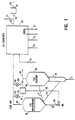
- Fig. 1 is a simplified process flow diagram of a preferred configuration, an FCC unit with flue gas analyzer controllers, and a CO boiler.
- Fig. 2. is plot of regenerator and CO boiler flue gas compositions as an FCC regenerator shifts from partial CO burn operation to the low NO x region and then back to full CO burn operation.
- the process of the present invention is an integral part of the catalytic cracking process.
- the essential elements of this process will be briefly reviewed in conjunction with a review of Fig. 1.
- a heavy, nitrogen containing feed is charged via line 2 to riser reactor 10.
- Hot regenerated catalyst removed from the regenerator via line 12 vaporizes fresh feed in the base of the riser reactor, and cracks the feed. Cracked products and spent catalyst are discharged into vessel 20, and separated. Spent catalyst is stripped in a stripping means not shown in the base of vessel 20, then stripped catalyst is charged via line 14 to regenerator 30. Cracked products are removed from vessel 20 via line 26 and charged to an FCC main column, not shown.
- Spent catalyst is maintained as a bubbling, dense phase fluidized bed in vessel 30.
- Regeneration gas almost always air, sometimes supplemented with oxygen, is added via line 34 to the base of the regenerator. Air flow is controlled by flow control valve 95.
- Regenerated catalyst is removed via line 12 and recycled to the base of the riser reactor. Flue gas is removed via line 36 and charged to preferred, but optional, CO converter 50.
- the CO converter will be a CO boiler, or CO combustion means 50, usually equipped with one or more heat recovery means 47, and/or a power recovery turbine 60.
- Flue gas from the FCC regenerator is charged via line 36 to the CO converter. Additional combustion air is added via line 41, to ensure there is sufficient air or oxygen present to burn enough CO to meet CO emissions standards. Where desired, ammonia or an ammonia precursor such as urea may be added via line 43, to react with any NO x formed during CO combustion in the CO converter or CO boiler 50. Additional combustion air is frequently added via line 45 to promote removal of additional amounts of CO. Flue gas is discharged via line 52 to a stack via line 54, or via line 56 to a conventional power recover turbine 60, and from there via line 62 to a stack, not shown.
- flue gas CO analyzer controller 70 and oxygen analyzer controller 80 are unique to the apparatus of the claimed invention. These sample, via sample lines 72 and 82, respectively, the flue gas, with results sent via signal transmission means 74 and 84 to controller means 90. A regeneration air control signal is sent via line 92 to regeneration air control valve 95 to control regeneration air flow.
- the controller means which can be a digital or analog computer, can determine if near stoichiometric air is being provided to the regenerator, and make appropriate adjustments.
- a drop in free oxygen content would increase air, while a rise in CO content above, e.g., 1,000 ppm would also increase air. More air is added until a predetermined amount of free oxygen is in the flue gas in line 36, e.g., 0.3 mole %. More air is added if the CO content of the flue gas becomes excessive, e.g., a CO content above 1:1 or 1 mole %. If the regenerator shifts into something approaching a complete CO burn mode, i.e., the CO content drops below 500 ppm, then the regenerator air rate will be reduced.
- the regenerator may have to be fairly hot, and/or a significant amount of dilute phase afterburning tolerated, in some regenerators for this control method to work. This is because is some regenerators, with poor air distribution or poor catalyst circulation, one side of the regenerator may be just in partial CO burn, while the other side is operating just within complete CO burn mode so that dilute phase afterburning results. In such units, more CO and more O 2 must usually be tolerated in the flue gas from the regenerator.
- a catalytic CO converter may be preferred for new units, as so little CO is present in our process that, for the first time, catalytic converters to remove CO from FCC flue gas are a viable option. In this way the fuel costs needed to drive the CO boiler in this uncomfortable mode of operation of the FCC regenerator can be eliminated or greatly reduced.
- the process of the present invention is useful for processing nitrogenous charge stocks, those containing more than 500 ppm total nitrogen compounds, and especially useful in processing stocks containing very high levels of nitrogen compounds, such as those with more than 1000 wt ppm total nitrogen compounds.
- the feeds may range from the typical, such as petroleum distillates or residual stocks, either virgin or partially refined, to the atypical, such as coal oils and shale oils.
- the feed frequently will contain recycled hydrocarbons, such as light and heavy cycle oils which have already been subjected to cracking.
- Preferred feeds are gas oils, vacuum gas oils, atmospheric resids, and vacuum resids.
- the present invention is most useful with feeds having an initial boiling point above about 343°C (650°F).
- the catalyst preferably contains relatively large amounts of large pore zeolite for maximum effectiveness, but such catalysts are readily available.
- the process will work with amorphous catalyst, but few modern FCC units use amorphous catalyst.
- Preferred catalysts for use herein will usually contain at least 10 wt % large pore zeolite in a porous refractory matrix such as silica-alumina, clay, or the like.
- the zeolite content is preferably much higher than this, and should usually be at least 20 wt % large pore zeolite, with optimum results achieved when unusually large amounts of large pore zeolite, in excess of 30 wt %, are present in the catalyst.
- the catalyst should contain from 30 to 60 wt % large pore zeolite.
- zeolite contents discussed herein refer to the zeolite content of the makeup catalyst, rather than the zeolite content of the equilibrium catalyst, or E-Cat. Much crystallinity is lost in the weeks and months that the catalyst spends in the harsh, steam filled environment of modern FCC regenerators, so the equilibrium catalyst will contain a much lower zeolite content by classical analytic methods. Most refiners usually refer to the zeolite content of their makeup catalyst, and the MAT (Modified Activity Test) or FAI (Fluidized Activity Index) of their equilibrium catalyst, and this specification follows this naming convention.
- MAT Modified Activity Test
- FAI Fluidized Activity Index
- zeolites such as X and Y zeolites, or aluminum deficient forms of these zeolites such as dealuminized Y (DEAL Y), ultrastable Y (USY) and ultrahydrophobic Y (UHP Y) may be used as the large pore cracking catalyst.
- the zeolites may be stabilized with Rare Earths, e.g., 0.1 to 10 wt % RE.
- Catalysts containing 20-60% USY or rare earth USY (REUSY) are especially preferred.
- the catalyst inventory may also contain one or more additives, either present as separate additive particles, or mixed in with each particle of the cracking catalyst.
- Additives can be added to enhance octane (medium pore size zeolites, sometimes referred to as shape selective zeolites, i.e., those having a Constraint Index of 1-12, and typified by ZSM-5, and other materials having a similar crystal structure).
- the FCC catalyst composition per se , forms no part of the present invention.
- afterburning shows up as a +17°C (+30°F), +28°C (+50°F) or +42°C (+75°F) change in temperature from the catalyst bed to the cyclones above the bed, with sufficient promoter added so that no more afterburning than this occurs.
- Additives may be used to adsorb SO x . These are believed to be primarily various forms of alumina, rare-earth oxides, and alkaline earth oxides, containing minor amounts of Pt, on the order of 0.1 to 2 ppm Pt. Additives for removal of SO x are available from several catalyst suppliers, such as Davison's “R” (trademark) or Katalizings International, Inc.'s "DESOX x " (trademark).
- the invention permits efficient use of these additives, even though the regenerator is not in complete CO combustion mode.
- SO x capture additives usually recover on the order of 60 to 70 % of the SO x , while in conventional partial CO burn mode SO x capture drops to 30 % or so.
- SO x additives can still capture more than 40 %, and preferably more than 50 % of the SO x while NO x emissions are drastically reduced.
- the reactor operation will usually be conventional all riser cracking FCC, such as disclosed in U.S. 4,421,636, incorporated by reference.
- Typical riser cracking reaction conditions include catalyst/oil ratios of 0.5:1 to 15:1 and preferably 3:1 to 8:1, and a catalyst contact time of 0.1-50 seconds, and preferably 0.5 to 10 seconds, and most preferably about 0.75 to 5 seconds, and riser top temperatures of 482°C (900°F) to about 593°C (1100°F), preferably 510°C (950°F) to 566°C (1050°F).
- riser catalyst acceleration zone in the base of the riser.
- Stripper cyclones disclosed in U.S. 4,173,527, Schatz and Heffley, incorporated herein by reference, may be used.
- Hot strippers heat spent catalyst by adding some hot, regenerated catalyst to spent catalyst. Suitable hot stripper designs are shown in U.S. 3,821,103, Owen et al, incorporated herein by reference. If hot stripping is used, a catalyst cooler may be used to cool the heated catalyst before it is sent to the catalyst regenerator. A preferred hot stripper and catalyst cooler is shown in U.S. 4,820,404, Owen, incorporated by reference.
- FCC steam stripping stripping conditions can be used, with the spent catalyst having essentially the same temperature as the riser outlet, and with 0.5 to 5 % stripping gas, preferably steam, added to strip spent catalyst.
- the FCC reactor and stripper conditions, per se can be conventional.
- the process and apparatus of the present invention can use conventional bubbling dense bed FCC regenerators.
- the process works even better when the FCC regenerator has a downstream CO boiler.
- Most regenerators with downstream CO boilers are bubbling dense bed regenerators, either swirl, cross-flow, or Orthoflow type.
- the carbon on regenerated catalyst can be conventional, typically less than 0.3 wt % coke, and more preferably less than 0.15 wt % coke, and most preferably even less.
- coke we mean not only carbon, but minor amounts of hydrogen associated with the coke, and perhaps even very minor amounts of unstripped heavy hydrocarbons which remain on catalyst. Expressed as wt % carbon, the numbers are essentially the same, but 5 to 10 % less.
- the carbon on regenerated catalyst can be the same as that produced by conventional FCC regenerators, the flue gas composition is unusual.
- the CO content of the flue gas should be low, less than 2 or 2.5 volume % CO.
- the CO content must also be considered with the oxygen content of the flue gas.
- the oxygen content of the flue gas should usually be less than 1/2 the amount of CO, by volume or molar amount. This will ensure that an overall reducing, or somewhat reducing atmosphere will be maintained in the regenerator. Poor air distribution, or poor catalyst circulation in the regenerator, may require use of slightly more regeneration air to achieve the desired regeneration.
- FCC regenerators in partial CO burn mode will have 4 to 8 mole % CO in the flue gas. Some may operate with lower amounts of CO, perhaps in the 2 or 3 mole % range, but none are believed to operate at steady state with 1 % CO in the flue gas. It would also be unusual to have such low amounts of oxygen in the flue gas, with such CO contents.
- a prior art regenerator in partial CO burn mode would have very little oxygen present in the flue gas, well within the limits preferred for the present invention, but would have much large amounts of CO present.
- a prior art regenerator in complete CO burn mode would usually have less than 500 ppm CO in the flue gas, but would always have more free oxygen present.
- Almost all bubbling bed regenerators operating in complete CO combustion mode are believed to operate with at least 1.0 mole % oxygen in the flue gas, and many operate with 1 or 2 mole % oxygen in the flue gas, so little or no CO will remain in the flue gas. Some may operate with as little as 0.7 % excess oxygen.
- Afterburning could disappear in a commercial unit if a large amount of resid is intentionally or accidentally added to the FCC feed.
- the extra coke make attributable to the resid would rapidly consume all the excess air in the regenerator, and eliminate or reduce afterburning.
- Afterburning could also be reduced or eliminated by a shift to a very clean, low coke making, feed. Less coke would be charged to the regenerator, and all the CO might be completely consumed in the dense bed (our unit will have almost the same heat release characteristics as a full CO burn regenerator, and will have a temperature which will permit CO burning within, or just above, the bubbling dense bed - this is discussed at greater length hereafter.).
- the temperature in our regenerator will be similar to temperatures in prior art regenerators operating in complete CO combustion mode, because more than 90 % of the coke on catalyst is burned to form CO 2 rather than CO. There will be slightly less heat release than in a prior art regenerator operating in full CO burn mode, offset by less excess air being heated and sent up the stack.
- regenerator temperatures low, to make such afterburning as may occur less troublesome.
- regenerator temperatures below 704°C (1300°F), and preferably below 677°C (1250°F) to reduce NO x emissions, but many units will be run above 704°C (1300°F), e.g., from 721 to 760°C (1330 to 1400°F).
- Some form of heat removal such as heat exchanger tubes, or less preferably, steam quench, may be used to reduce regenerator temperature if desired.
- H.E.R. high efficiency regenerators
- H.E.R.'s inherently make better use of regeneration air, but most still operate with 1 % O 2 or more in the flue gas, so slightly better use can be made of regeneration air from the process of the present invention.
- regenerators are controlled primarily by adjusting the amount of regeneration air that is added, other equivalent control schemes are available which keep the air constant and change some other condition. Constant air rate, with changes in feed rate changing the coke yield, is an acceptable way to modify regenerator operation. Constant air, with variable feed preheat, or variable regenerator air preheat, are also acceptable. Finally, catalyst coolers can be used to remove heat from a unit. If a unit is not generating enough coke to stay in heat balance, torch oil, or some other fuel may be burned in the regenerator.
- the present invention does not require a CO boiler, it usually will be preferred to operate with a CO boiler, or other means such as a catalytic converter, to remove additional amounts of CO from regenerator flue gas. There is so little CO in the flue gas from our regenerator that the heat recovered from a CO boiler will not usually justify the installation of a CO boiler.
- a CO boiler will usually be required to comply with local CO emissions limits, and also provides more degrees of freedom to operate the FCC regenerator so NO x emissions are greatly reduced. CO boiler operation will be reviewed first, followed by a review of some other means to reduce CO emissions.
- any conventional CO boiler can be used herein.
- the CO boiler is operated in multiple stages, to reduce the flame temperature occurring in any one stage and limit NO x formation in an oxidizing atmosphere.
- Use of low NO x burners to burn the CO is preferred.
- Low NO x burners are also preferred to burn the fuel gas which will probably be needed to keep the CO boiler "lit.”
- Efficient mixing between the CO gas and the fuel gas will minimize the fuel gas flame tip temperature. This can be accomplished, for example, by introducing the flue gas, premixed with air, at high velocity in the annular region around the fuel gas flame.
- the adiabatic temperature of the CO gas (even with up to 10 % CO) is around 760 - 982°C (1400 - 1800°F), which is much lower than the flame tip temperature associated with burning fuel gas [>1538°C (>2800°F)]. Because the fuel gas volume is small, typically only 0.1 to 2 % of the flue gas, the adiabatic temperature of the mixture is approximately that of the CO gas. Mixing rapidly will keep the flame tip temperature closer to the 1400 - 1800 region, and minimize NO x formation.
- low NO x burners such as those available from John Zink and other burner manufacturers may be used.
- ammonia or an ammonia precursor such as urea may be beneficial to add to the CO boiler. These materials react quickly with NO x to reduce it to nitrogen.
- Pt based CO combustion promoter may promote some additional formation of NO x from NO x precursors in the FCC regenerator flue gas compared to a conventional CO boiler. Usually this will be tolerable, as most of the NO x precursors in flue gas from the regenerator will be eliminated upstream of the CO boiler.
- the flue gas produced downstream of CO converter will have an unusually low level of both NO x and CO.
- the NO x and CO levels should be below 100 ppm.
- the NO x and CO levels will both be below 50 ppm.
- Tests were conducted to determine the effectiveness of various modes of operation of a bubbling bed catalyst regenerator at reducing NO x emissions, and reducing the formation of NO x precursors. These tests were run on a commercial unit, with a cross-flow regenerator. The catalyst was maintained as a bubbling, dense phase fluidized bed, with spent catalyst added from one side of the regenerator, and regenerated catalyst removed from the other side. Test results are summarized in Figure 2.
- Figure 2 shows how regenerator emissions, and CO boiler emissions change as a unit goes from partial CO combustion to the region claimed, and then back into partial CO combustion.
- the FCC feed contained 0.2 wt % total nitrogen.
- the CO boiler was kept hot enough so that the CO could be efficiently burned in the boiler, this required addition of enough fuel gas to compensate for the reduced amount of CO present in regenerator flue gas.
- the adiabatic combustion temperature for the mix of CO containing flue gas and fuel gas was always at least 871°C (1600°F).
- the CO boiler was run so that the flue gas from it contained about 1.6 vol % oxygen, wet gas basis. We do not think the CO boiler was sensitive to oxygen concentration, i.e., we could find little correlation between NO x and oxygen levels.
- the CO boiler was believed to be even more effective than the results shown in the Figure, in that a small leak in the bypass line around the CO boiler was suspected by the refiner.
- the CO conversions are good regardless, and clearly show that reduced NO x was not achieved at the expense of higher boiler CO emissions.
- the FCC unit would be started conventionally, and the regenerator run in either partial or full CO burn mode. Then the air rate to the regenerator should be adjusted (increased in partial combustion, decreased in full combustion mode) until the flue gas composition is in the specified range. The concentration of CO and O 2 from the regenerator should be monitored continuously.
- One possible control strategy would be to manipulate the air rate to control the quantity (CO/2) - O 2 . When this quantity is 0, there is stoichiometric O 2 present to complete combustion of CO to CO 2 . Optimum operation would be achieved by controlling this quantity between 1.0 and -0.4, preferably between 0.5 and -0.1, and most preferably between 0.0 and 0.25.
- Afterburn particularly in units with a large diameter dense bed regenerator, will likely be a problem at these conditions. Based on our experimental results, it may be very beneficial to have large amounts of afterburning.
- we would like to match closely air supply to coke supply e.g., plug up portions of the air grid that may be letting too much air into one point in the regenerator.
- Use of steam or water may be needed to quench dilute phase, cyclone, or flue gas line temperatures. Cyclone metallurgy that can withstand high operating temperatures may be required.
- the process of the present invention can be readily used in existing bubbling bed FCC regenerators with CO boilers with no hardware changes. Operation will be facilitated if the regenerator is equipped with fairly sophisticated controls, permitting control to be based at least in part on one or more flue gas compositions, such as NO x , CO, or free oxygen.
- flue gas compositions such as NO x , CO, or free oxygen.
- the flue gas eventually discharged to the atmosphere from our unit will have less than 1/2, and perhaps only 25 %, or 20 % , or even only 10 % or less of the NO x emissions which would be produced by burning the same amount of nitrogen containing coke in either a bubbling bed regenerator operating in full CO burn mode, or in one in partial CO burn mode, with a downstream CO boiler.
- the process and apparatus of the present invention provide a way for refiners to greatly reduce NO x emissions, while continuing to meet CO emissions specifications, and while using SO x capture additives at reasonable effectiveness.
Landscapes
- Chemical & Material Sciences (AREA)
- Oil, Petroleum & Natural Gas (AREA)
- Engineering & Computer Science (AREA)
- Chemical Kinetics & Catalysis (AREA)
- Organic Chemistry (AREA)
- General Chemical & Material Sciences (AREA)
- Materials Engineering (AREA)
- Production Of Liquid Hydrocarbon Mixture For Refining Petroleum (AREA)
- Exhaust Gas Treatment By Means Of Catalyst (AREA)
- Devices And Processes Conducted In The Presence Of Fluids And Solid Particles (AREA)
- Treating Waste Gases (AREA)
Claims (10)
- Verfahren zum katalytischen Cracken einer stickstoffhaltigen Kohlenwasserstoffbeschickung in geringersiedende Produkte durch Cracken der Beschickung mit einem heißen, regenerierten Crackkatalysator in einem Reaktor zum katalytischen Wirbelschichtcracken (FCC), wodurch eine Mischung aus Crackprodukten und verbrauchtem Crackkatalysator hergestellt wird, der Koks und Stickstoffverbindungen enthält; Abtrennen der Crackprodukte vom verbrauchten Crackkatalysator, wodurch Crackproduktdampf und verbrauchter Katalysator erzeugt werden; Strippen des verbrauchten Katalysators in einem Katalysatorstripper, wodurch gestrippter, verbrauchter Katalysator erzeugt wird, der Koks und Stickstoffverbindungen enthält; Regenerieren des gestrippten, verbrauchten Katalysators in einem Regenerator mit aufwallendem dichtem Bett mit Sauerstoff bei einer Temperatur von 593 bis 760°C (1100 bis 1400°F) in einem Regenerator für Katalysator, wodurch regenerierter Katalysator und ein Abgasstrom erzeugt wird, der 0,00 bis 1,00 Mol-% Sauerstoff, 100 bis 25.000 ppm CO, auf das Volumen bezogen, und NOx und NOx-Vorstufen enthält; Gewinnen des regenerierten Katalysators aus dem Regenerator und dessen Rückführung zum Crackreaktor; Leiten des Abgasstroms zu einem CO-Brenner und Verbrennen des Regeneratorabgases im CO-Brenner mit weiterem sauerstoffhaltigem Gas, wodurch mindestens 50 % des CO-Gehalts des Regeneratorabgases und mindestens 50 % der verflüchtigten NOx-Vorstufen im Regeneratorabgas oxidiert werden und eine CO-Brennerabgas erzeugt wird, das 0,05 bis 6 Mol-% Sauerstoff, weniger als 200 ppm CO und weniger als 100 ppm NOx enthält.
- Verfahren nach Anspruch 1, wobei das Regeneratorabgas 0,0 bis 3 % Sauerstoff und 500 bis 10.000 ppm CO enthält und das CO-Brennerabgas weniger als 1,5 % Sauerstoff, weniger als 100 ppm CO und weniger als 50 ppm NOx enthält.
- Verfahren nach Anspruch 1 oder 2, wobei im CO-Brenner zusätzlicher Brennstoff in einer Menge verbrannt wird, die zumindest gleich dem Heizwert des Regeneratorabgases ist.
- Verfahren nach einem der Ansprüche 1 bis 3, wobei das CO-Brennerabgas weniger als 25 ppm NOx und weniger als 25 ppm CO enthält.
- Verfahren nach einem der Ansprüche 1 bis 4, wobei im Regenerator eine Nachverbrennung mit 28 bis 111°C (50 bis 200°F) auftritt.
- Verfahren nach einem der Ansprüche 1 bis 5, wobei mindestens 50 % des NOx im Regenerator in Stickstoff überführt werden.
- Verfahren nach einem der Ansprüche 1 bis 6, welches umfaßt: periodisches Überwachen des NOx-Gehaltes des vom CO-Brenner abgegebenen Gases und Regelung der Bedingungen der Katalysatorregenerierung entsprechend einem Anstieg des NOx-Gehaltes der abgegebenen Abluft durch Erhöhung der Erzeugung von NOx und der Umwandlung von NOx im Regenerator, und Verringerung der im Regenerator erzeugten Menge von NOx-Vorstufen durch Erhöhung der Sauerstoffmenge im Regeneratorabgas, wobei die Sauerstoffkonzentration im Bereich von 0,0 bis 0,75 Mol-% gehalten wird.
- Verfahren nach einem der Ansprüche 1 bis 6, welches umfaßt: periodisches Überwachen des NOx-Gehaltes des vom CO-Brenner abgegebenen Gases und Regelung der Bedingungen der Katalysatorregenerierung entsprechend einem Anstieg des NOx-Gehaltes der abgegebenen Abluft durch Erhöhung der Erzeugung von NOx und der Umwandlung von NOx im Regenerator, und Verringerung der im Regenerator erzeugten Menge von NOx-Vorstufen durch Verringerung des CO-Gehaltes des Regeneratorabgases, wobei die CO-Konzentration im Bereich von 100 ppm Volumen bis 10.000 ppm Volumen gehalten wird.
- Verfahren nach einem der Ansprüche 1 bis 6, welches umfaßt: periodisches Überwachen des NOx-Gehaltes des vom CO-Brenner abgegebenen Gases und Regelung der Bedingungen der Katalysatorregenerierung entsprechend einem Anstieg des NOx-Gehaltes der abgegebenen Abluft durch Erhöhung der Erzeugung von NOx und der Umwandlung von NOx im Regenerator, und Verringerung der im Regenerator erzeugten Menge von NOx-Vorstufen durch Umwandlung von zumindest dem größten Teil des NOx und der NOx-Vorstufen im Regenerator, die durch Verbrennen von Stickstoffverbindungen im Regenerator erzeugt wurden, wodurch ein Regeneratorabgas erzeugt wird, das einen geringeren Gesamtgehalt an NOx und NOx-Vorstufen aufweist.
- Verfahren nach Anspruch 9, wobei die Abluft vom CO-Brenner weniger als 50 ppm NOx und weniger als 100 ppm CO enthält.
Applications Claiming Priority (2)
| Application Number | Priority Date | Filing Date | Title |
|---|---|---|---|
| US07/903,406 US5268089A (en) | 1992-06-24 | 1992-06-24 | FCC of nitrogen containing hydrocarbons and catalyst regeneration |
| US903406 | 1992-06-24 |
Publications (2)
| Publication Number | Publication Date |
|---|---|
| EP0578401A1 EP0578401A1 (de) | 1994-01-12 |
| EP0578401B1 true EP0578401B1 (de) | 1999-03-24 |
Family
ID=25417451
Family Applications (1)
| Application Number | Title | Priority Date | Filing Date |
|---|---|---|---|
| EP93304812A Expired - Lifetime EP0578401B1 (de) | 1992-06-24 | 1993-06-21 | FCC-Regenerierungsverfahren und Vorrichtung zur Reduktion von NOX |
Country Status (7)
| Country | Link |
|---|---|
| US (1) | US5268089A (de) |
| EP (1) | EP0578401B1 (de) |
| JP (1) | JP3478851B2 (de) |
| AU (1) | AU664098B2 (de) |
| CA (1) | CA2098931C (de) |
| DE (1) | DE69324073T2 (de) |
| ES (1) | ES2129497T3 (de) |
Families Citing this family (30)
| Publication number | Priority date | Publication date | Assignee | Title |
|---|---|---|---|---|
| CA2156464C (en) | 1994-09-30 | 1999-07-20 | Raghu K. Menon | Reduction of emissions from fcc regenerators |
| US5716514A (en) * | 1995-08-30 | 1998-02-10 | Mobil Oil Corporation | FCC NOx reduction by turbulent/laminar thermal conversion |
| US5705053A (en) * | 1995-08-30 | 1998-01-06 | Mobil Oil Corporation | FCC regenerator NOx reduction by homogeneous and catalytic conversion |
| US5830346A (en) * | 1995-08-30 | 1998-11-03 | Mobil Oil Corporation | FCC regenerator in partial CO burn with downstream air addition |
| EP1201729A3 (de) * | 2000-10-31 | 2002-11-20 | The Boc Group, Inc. | Katalytischer Krackregenerator in der Flüssigphase mit reduzierter Emission von NOx |
| US6579820B2 (en) | 2001-03-21 | 2003-06-17 | The Boc Group, Inc. | Reactor modifications for NOx reduction from a fluid catalytic cracking regeneration vessel |
| US20060198778A1 (en) * | 2002-06-05 | 2006-09-07 | Barckholtz Timothy A | Reduction of NOx in fluid catalytic cracking regenerator off-gas streams |
| US20040005263A1 (en) * | 2002-06-05 | 2004-01-08 | Exxonmobil Research And Engineering Company | Process for reducing NOx in waste gas streams using sodium chlorite |
| US20060198779A1 (en) * | 2002-06-05 | 2006-09-07 | Hurst Boyd E | Selective non-catalytic reduction of NOx |
| US20040022708A1 (en) * | 2002-06-05 | 2004-02-05 | Exxonmobil Research And Engineering Company | Selective non-catalytic reduction of NOx |
| US20060233688A1 (en) * | 2002-06-05 | 2006-10-19 | Barckholtz Timothy A | Non-catalytic reduction and oxidation process for the removal of NOx |
| US20040074809A1 (en) * | 2002-10-21 | 2004-04-22 | George Yaluris | Reduction of gas phase reduced nitrogen species in partial burn FCC processes |
| US20040262197A1 (en) * | 2003-06-24 | 2004-12-30 | Mcgregor Duane R. | Reduction of NOx in low CO partial-burn operation using full burn regenerator additives |
| CN1323757C (zh) * | 2003-09-26 | 2007-07-04 | 中国石油化工集团公司 | 不完全再生烟气烟道燃烧方法 |
| US20050100494A1 (en) | 2003-11-06 | 2005-05-12 | George Yaluris | Ferrierite compositions for reducing NOx emissions during fluid catalytic cracking |
| ITMI20040198A1 (it) * | 2004-02-09 | 2004-05-09 | Snam Progetti | Dispositivo reattore-rigeneratore e suo impiego nella produzione di stirene |
| US20050232839A1 (en) | 2004-04-15 | 2005-10-20 | George Yaluris | Compositions and processes for reducing NOx emissions during fluid catalytic cracking |
| US7304011B2 (en) | 2004-04-15 | 2007-12-04 | W.R. Grace & Co. -Conn. | Compositions and processes for reducing NOx emissions during fluid catalytic cracking |
| RU2007139330A (ru) * | 2005-03-24 | 2009-04-27 | В.Р.Грейс Энд Ко.-Конн. (Us) | СПОСОБ РЕГУЛИРОВАНИЯ ВЫБРОСОВ NOx В УСТАНОВКАХ КАТАЛИТИЧЕСКОГО КРЕКИНГА В ПСЕВДООЖИЖЕННОМ СЛОЕ |
| KR101382014B1 (ko) | 2005-04-27 | 2014-04-04 | 더블유.알. 그레이스 앤드 캄파니-콘. | 유동상 접촉 분해 중의 NOx 방출 감소를 위한 조성물 및공정 |
| US7470412B2 (en) * | 2005-12-21 | 2008-12-30 | Praxair Technology, Inc. | Reduction of CO and NOx in regenerator flue gas |
| FR2909907B1 (fr) * | 2006-12-13 | 2009-06-26 | Inst Francais Du Petrole | Nouveau dispositif permettant de diminuer les emissions de nox des fumees de fcc |
| US20110297584A1 (en) * | 2009-01-22 | 2011-12-08 | Ye Mon Chen | Systems and methods for processing a catalyst regenerator flue gas |
| US7931881B2 (en) * | 2009-09-25 | 2011-04-26 | Babcock Power Environmental Inc. | Integrated boiler and air pollution control systems |
| US8618011B2 (en) | 2010-04-09 | 2013-12-31 | Kellogg Brown & Root Llc | Systems and methods for regenerating a spent catalyst |
| US8618012B2 (en) | 2010-04-09 | 2013-12-31 | Kellogg Brown & Root Llc | Systems and methods for regenerating a spent catalyst |
| CN102527208B (zh) * | 2010-12-30 | 2014-12-31 | 中国石油化工股份有限公司 | 一种脱除催化裂化再生烟气中硫氧化物、氮氧化物的方法 |
| US20120312722A1 (en) * | 2011-06-10 | 2012-12-13 | Uop, Llc | Process for fluid catalytic cracking |
| FI20206383A1 (en) * | 2020-12-30 | 2022-07-01 | Neste Oyj | Co-treatment route for hydrogen processing of polymer waste-based material |
| CN116836722B (zh) * | 2022-03-25 | 2025-11-04 | 中国石油化工股份有限公司 | 降低两段再生催化裂化装置烟气中VOCs和NOx排放量的方法 |
Family Cites Families (8)
| Publication number | Priority date | Publication date | Assignee | Title |
|---|---|---|---|---|
| US4198287A (en) * | 1976-02-02 | 1980-04-15 | Uop Inc. | Method of regenerating coke-contaminated catalyst with simultaneous combustion of carbon monoxide |
| US4180454A (en) * | 1978-01-03 | 1979-12-25 | Exxon Research & Engineering Co. | Method for combusting carbon monoxide in a fluid catalytic cracking process |
| US4812430A (en) * | 1987-08-12 | 1989-03-14 | Mobil Oil Corporation | NOx control during multistage combustion |
| US5062944A (en) * | 1989-11-06 | 1991-11-05 | Mobil Oil Corporation | Catalytic cracking process with multiple catalyst outlets |
| US5002654A (en) * | 1989-12-28 | 1991-03-26 | Mobil Oil Corporation | Reducing NOx emissions with zinc catalyst |
| US5077251A (en) * | 1990-07-17 | 1991-12-31 | Mobil Oil Corporation | Control of multistage catalyst regeneration with both partial and full co combustion |
| US5077252A (en) * | 1990-07-17 | 1991-12-31 | Mobil Oil Corporation | Process for control of multistage catalyst regeneration with partial co combustion |
| US5110775A (en) * | 1990-12-28 | 1992-05-05 | Mobil Oil Corporation | Two stage combustion process for cracking catalyst regeneration |
-
1992
- 1992-06-24 US US07/903,406 patent/US5268089A/en not_active Expired - Lifetime
-
1993
- 1993-06-21 EP EP93304812A patent/EP0578401B1/de not_active Expired - Lifetime
- 1993-06-21 DE DE69324073T patent/DE69324073T2/de not_active Expired - Lifetime
- 1993-06-21 ES ES93304812T patent/ES2129497T3/es not_active Expired - Lifetime
- 1993-06-22 AU AU41394/93A patent/AU664098B2/en not_active Ceased
- 1993-06-22 CA CA002098931A patent/CA2098931C/en not_active Expired - Fee Related
- 1993-06-24 JP JP15324293A patent/JP3478851B2/ja not_active Expired - Fee Related
Also Published As
| Publication number | Publication date |
|---|---|
| EP0578401A1 (de) | 1994-01-12 |
| JP3478851B2 (ja) | 2003-12-15 |
| US5268089A (en) | 1993-12-07 |
| DE69324073T2 (de) | 1999-07-15 |
| CA2098931A1 (en) | 1993-12-25 |
| CA2098931C (en) | 2003-01-14 |
| ES2129497T3 (es) | 1999-06-16 |
| AU4139493A (en) | 1994-01-06 |
| AU664098B2 (en) | 1995-11-02 |
| JPH0693271A (ja) | 1994-04-05 |
| DE69324073D1 (de) | 1999-04-29 |
Similar Documents
| Publication | Publication Date | Title |
|---|---|---|
| US5268089A (en) | FCC of nitrogen containing hydrocarbons and catalyst regeneration | |
| US5372706A (en) | FCC regeneration process with low NOx CO boiler | |
| EP0539529B1 (de) | Verfahren zur steuerung der mehrstufigen katalysatorregenerierung mit mit partieller co-verbrennung | |
| US5705053A (en) | FCC regenerator NOx reduction by homogeneous and catalytic conversion | |
| AU649268B2 (en) | Process for control of multistage catalyst regeneration with full then partial CO combustion | |
| US5716514A (en) | FCC NOx reduction by turbulent/laminar thermal conversion | |
| US5830346A (en) | FCC regenerator in partial CO burn with downstream air addition | |
| EP0435880B1 (de) | Apparat und verfahren zur regenerierung von kokshaltigen fliessbettkrackkatalysatoren | |
| AU5525790A (en) | Heavy oil catalytic cracking process and apparatus | |
| US5021144A (en) | Process for the reduction of NOX in an FCC regeneration system by select control of CO oxidation promoter in the regeneration zone | |
| US5382352A (en) | Conversion of NOx in FCC bubbling bed regenerator | |
| US5130012A (en) | Process and apparatus for reducing NOx emissions from high-efficiency FFC regenerators | |
| AU641965B2 (en) | Reducing nox emissions with group IIIB compounds | |
| US4988432A (en) | Reducing NOx emissions with antimony additive | |
| US4985133A (en) | Reducing NOx emissions from FCC regenerators by segregated cracking of feed | |
| WO1992001511A1 (en) | Process and apparatus for control of multistage catalyst regeneration with full co combustion | |
| US4997800A (en) | Fluidized bed combustion | |
| US4395325A (en) | Reducing sulfur trioxide concentration in regeneration zone flue gas |
Legal Events
| Date | Code | Title | Description |
|---|---|---|---|
| PUAI | Public reference made under article 153(3) epc to a published international application that has entered the european phase |
Free format text: ORIGINAL CODE: 0009012 |
|
| AK | Designated contracting states |
Kind code of ref document: A1 Designated state(s): BE DE ES FR GB IT NL |
|
| 17P | Request for examination filed |
Effective date: 19940617 |
|
| 17Q | First examination report despatched |
Effective date: 19960205 |
|
| GRAG | Despatch of communication of intention to grant |
Free format text: ORIGINAL CODE: EPIDOS AGRA |
|
| GRAG | Despatch of communication of intention to grant |
Free format text: ORIGINAL CODE: EPIDOS AGRA |
|
| GRAH | Despatch of communication of intention to grant a patent |
Free format text: ORIGINAL CODE: EPIDOS IGRA |
|
| GRAH | Despatch of communication of intention to grant a patent |
Free format text: ORIGINAL CODE: EPIDOS IGRA |
|
| GRAA | (expected) grant |
Free format text: ORIGINAL CODE: 0009210 |
|
| AK | Designated contracting states |
Kind code of ref document: B1 Designated state(s): BE DE ES FR GB IT NL |
|
| ET | Fr: translation filed | ||
| REF | Corresponds to: |
Ref document number: 69324073 Country of ref document: DE Date of ref document: 19990429 |
|
| REG | Reference to a national code |
Ref country code: ES Ref legal event code: FG2A Ref document number: 2129497 Country of ref document: ES Kind code of ref document: T3 |
|
| PLBE | No opposition filed within time limit |
Free format text: ORIGINAL CODE: 0009261 |
|
| STAA | Information on the status of an ep patent application or granted ep patent |
Free format text: STATUS: NO OPPOSITION FILED WITHIN TIME LIMIT |
|
| 26N | No opposition filed | ||
| REG | Reference to a national code |
Ref country code: GB Ref legal event code: IF02 |
|
| PGFP | Annual fee paid to national office [announced via postgrant information from national office to epo] |
Ref country code: FR Payment date: 20100617 Year of fee payment: 18 Ref country code: ES Payment date: 20100615 Year of fee payment: 18 |
|
| PGFP | Annual fee paid to national office [announced via postgrant information from national office to epo] |
Ref country code: IT Payment date: 20100621 Year of fee payment: 18 |
|
| PGFP | Annual fee paid to national office [announced via postgrant information from national office to epo] |
Ref country code: NL Payment date: 20100607 Year of fee payment: 18 Ref country code: BE Payment date: 20100630 Year of fee payment: 18 |
|
| PGFP | Annual fee paid to national office [announced via postgrant information from national office to epo] |
Ref country code: GB Payment date: 20100401 Year of fee payment: 18 Ref country code: DE Payment date: 20100630 Year of fee payment: 18 |
|
| BERE | Be: lapsed |
Owner name: *MOBIL OIL CORP. Effective date: 20110630 |
|
| REG | Reference to a national code |
Ref country code: NL Ref legal event code: V1 Effective date: 20120101 |
|
| GBPC | Gb: european patent ceased through non-payment of renewal fee |
Effective date: 20110621 |
|
| PG25 | Lapsed in a contracting state [announced via postgrant information from national office to epo] |
Ref country code: IT Free format text: LAPSE BECAUSE OF NON-PAYMENT OF DUE FEES Effective date: 20110621 |
|
| REG | Reference to a national code |
Ref country code: FR Ref legal event code: ST Effective date: 20120229 |
|
| PG25 | Lapsed in a contracting state [announced via postgrant information from national office to epo] |
Ref country code: BE Free format text: LAPSE BECAUSE OF NON-PAYMENT OF DUE FEES Effective date: 20110630 |
|
| REG | Reference to a national code |
Ref country code: DE Ref legal event code: R119 Ref document number: 69324073 Country of ref document: DE Effective date: 20120103 |
|
| PG25 | Lapsed in a contracting state [announced via postgrant information from national office to epo] |
Ref country code: DE Free format text: LAPSE BECAUSE OF NON-PAYMENT OF DUE FEES Effective date: 20120103 Ref country code: FR Free format text: LAPSE BECAUSE OF NON-PAYMENT OF DUE FEES Effective date: 20110630 |
|
| PG25 | Lapsed in a contracting state [announced via postgrant information from national office to epo] |
Ref country code: NL Free format text: LAPSE BECAUSE OF NON-PAYMENT OF DUE FEES Effective date: 20120101 |
|
| PG25 | Lapsed in a contracting state [announced via postgrant information from national office to epo] |
Ref country code: GB Free format text: LAPSE BECAUSE OF NON-PAYMENT OF DUE FEES Effective date: 20110621 |
|
| REG | Reference to a national code |
Ref country code: ES Ref legal event code: FD2A Effective date: 20130417 |
|
| PG25 | Lapsed in a contracting state [announced via postgrant information from national office to epo] |
Ref country code: ES Free format text: LAPSE BECAUSE OF NON-PAYMENT OF DUE FEES Effective date: 20110622 |