EP0578400B1 - Optical low coherence reflectometer with delay sequence - Google Patents
Optical low coherence reflectometer with delay sequence Download PDFInfo
- Publication number
- EP0578400B1 EP0578400B1 EP93304811A EP93304811A EP0578400B1 EP 0578400 B1 EP0578400 B1 EP 0578400B1 EP 93304811 A EP93304811 A EP 93304811A EP 93304811 A EP93304811 A EP 93304811A EP 0578400 B1 EP0578400 B1 EP 0578400B1
- Authority
- EP
- European Patent Office
- Prior art keywords
- light
- interferometer
- light signal
- optical
- delay
- Prior art date
- Legal status (The legal status is an assumption and is not a legal conclusion. Google has not performed a legal analysis and makes no representation as to the accuracy of the status listed.)
- Expired - Lifetime
Links
Images


Classifications
-
- G—PHYSICS
- G01—MEASURING; TESTING
- G01M—TESTING STATIC OR DYNAMIC BALANCE OF MACHINES OR STRUCTURES; TESTING OF STRUCTURES OR APPARATUS, NOT OTHERWISE PROVIDED FOR
- G01M11/00—Testing of optical apparatus; Testing structures by optical methods not otherwise provided for
- G01M11/30—Testing of optical devices, constituted by fibre optics or optical waveguides
- G01M11/31—Testing of optical devices, constituted by fibre optics or optical waveguides with a light emitter and a light receiver being disposed at the same side of a fibre or waveguide end-face, e.g. reflectometers
- G01M11/3172—Reflectometers detecting the back-scattered light in the frequency-domain, e.g. OFDR, FMCW, heterodyne detection
Landscapes
- Physics & Mathematics (AREA)
- Optics & Photonics (AREA)
- Chemical & Material Sciences (AREA)
- Analytical Chemistry (AREA)
- General Physics & Mathematics (AREA)
- Instruments For Measurement Of Length By Optical Means (AREA)
- Testing Of Optical Devices Or Fibers (AREA)
- Investigating Or Analysing Materials By Optical Means (AREA)
Description
- The present invention relates to optical measurements, and more particularly, to optical reflectometry.
- The increased use of optical components in communication and data processing systems has created an increased need for a method for measuring optical inhomogeneities in optical components. For example, in fiber optic based communication systems there is a need to measure splice losses and the location of non-reflecting fiber breaks. Similarly, there is a need for a methodology for characterizing optical components such as silica based optical planar wave guides and LiNbO₃ wave guides.
- One method for analyzing inhomogeneities in optical fibers is optical time domain reflectometry. In this method, a light pulse is transmitted down the optical fiber and the backscattered light resulting from the interaction of the light pulse with an inhomogeneity in the fiber is measured. The time delay between the incident light pulse and reflected light provides information on the location of the inhomogeneity. The amplitude of the backscatter light signal provides information on the degree of inhomogeneity. In conventional pulsed techniques, the measurement of the backscattered light becomes more difficult as spatial resolution is improved. Higher spatial resolution simultaneously results in lower levels of Rayleigh backscattered light power and increased noise power due to larger receiver bandwidths.
- White light interferometry or optical low-coherence reflectometry provides a technique that allows several orders of magnitude improvement in both sensitivity and spatial resolution compared to conventional time domain methods. Spatial resolutions of 20 to 40 microns have been reported using this technique. This resolution is equivalent to the resolution that would be obtained using pulse widths of a few hundred femtoseconds using conventional pulse techniques. For these resolutions, the average Rayleigh backscattered levels for standard telecommunications fibers are of the order of -115 dB. Reflection sensitivities have been limited to values close to the backscattered levels due to the noise intensity of low-coherence optical sources. However, a reflection sensitivity of -136 dB has been demonstrated at a wavelength of 1.3 microns using a high-power superluminescent diode and a balanced detection scheme to eliminate the effects of intensity noise [Takada, et al., "Rayleigh Backscattering Measurements of Single-Mode Fibers by Low Coherence Optical Time-Domain Reflectometry With 14 mm Spatial Resolution", Appl. Phys. Lett., 59 , p.143, 1991].
- While optical low-coherence reflectometry provides the resolution and sensitivity to perform the measurements in question, the distances over which optical low-coherence reflectometers can scan is limited to about 0.5 meters. This limitation is due to the limited range over which a mirror can be moved using a lead-screw. Hence, inhomogeneities that are separated by more than 0.5 meters cannot be simultaneously detected. There is a need to dramatically increase the scan range because many optical devices that are to be probed have fiber lead lengths greater than one meter. To scan for inhomogeneities separated by larger distances, multiple measurements in the 0.5 meter range must be made with the aid of fixed optical delay lines. This procedure is time consuming.
- Broadly, it is an object of the present invention to provide an improved optical low-coherence reflectometry measurement apparatus.
- It is a further object of the present invention to provide an optical low-coherence reflectometry system that can scan for inhomogeneities separated by many meters.
- These and other objects of the present invention will become apparent to those skilled in the art from the following detailed description of the invention and the accompanying drawings.
- The present invention comprises an optical interferometer for measuring the optical properties of a device. The device is illuminated by an optical low-coherence source. Light from the source is split into first and second light signals by a coupler. The first light signal is applied to the device and a portion of the light reflected therefrom is collected. A series of light signals is generated from said second light signal, each said generated light signal being displaced in time with respect to the original light signal in the sequence. The generated sequence of light signals is then combined with the light collected from the device and the amplitude of the combined signals detected.
- Figure 1 is a block diagram of an optical low-coherence reflectometer.
- Figure 2 is a block diagram of one embodiment of an optical low-coherence reflectometer according to the present invention.
- Figure 3 is a block diagram of a second embodiment of an optical low-coherence reflectometer according to the present invention.
- Figure 4 is a block diagram of a third embodiment of an optical low-coherence reflectometer according to the present invention.
- Figure 5 illustrates an alternative type of resonant delay line.
- Figure 6 is a block diagram of a fourth embodiment of an optical low-coherence reflectometer according to the present invention.
- The manner in which an optical low-coherence reflectometer utilizing a balanced detector operates may be more easily understood with reference to Figure 1 which is a schematic diagram of an optical low-
coherence reflectometer 10 for measuring the optical properties of adevice 12. A low-coherence light source 14 is used to illuminatedevice 12. Optical coherence length of the light fromlight source 14 determines the spatial resolution of the measurements. A suitable light source may be constructed by utilizing the amplified spontaneous emission from an erbium-doped fiber. Such fibers are known to the optical arts, and hence, will not be discussed in more detail here. Light fromsource 14 is split bycoupler 16 which is connected tosource 14 by fiber 13.Coupler 16 divides the light between two arms of the interferometer. The firstarm comprising fiber 15 delivers light todevice 12. The polarization of the light is controlled by twopolarization control loops 18. An optional phase shifter 11 may be included in this arm of the interferometer. Backscattered light fromdevice 12 is returned tocoupler 16 viafiber 15. A portion of the backscattered light is delivered to asecond coupler 22 viafiber 20. - The second arm of the interferometer has a variable time delay. The portion of the light from
coupler 16 that is not routed downfiber 15 is routed tofiber 23 and provides a reference light signal. This light is collimated bylens 30 onto aretroreflecting mirror 24 which is mounted on a moving stage. The motion in the Z direction alters the optical path length of the second arm of the interferometer. Light leavingmirror 24 is imaged intofiber 26 bylens 31 and delivered tocoupler 22.Coupler 22 acts as an adder for combining the backscattered light fromdevice 12 and the reference signal light fromsource 14. When the time delay in the second arm of the interferometer matches the time delay of a reflection fromdevice 12, coherent interference occurs producing a beat signal at a predetermined frequency. The power in the light signal at the beat frequency is detected by a balanced detector 32 comprising twophotodiodes adder 33. The balanced detector removes any intensity noise on the incoming optical signals. The subtracted output is then processed electronically to detect the strength of the interference signal. For example, the power spectrum of the subtracted output may be measured by aspectrum analyzer 29. - The beat frequency is preferably chosen to coincide with a minimum in the receiver noise floor. This frequency may be controlled by either of two methods. The preferred method uses phase shifter 11 which is sawtooth ramped over a range of 180 degrees producing a serrodyne frequency shift on the returning signal. In this case, the beat signal will be at the serrodyne frequency with a strength dependent on the magnitude of the reflection. In this type of system,
mirror 24 is stepped through each position and the signal averaged for a sufficient time to provide the desired signal to noise. Alternatively, phase shifter 11 can be eliminated andmirror 24 moved in a continuous manner during the measurement. The continuous motion results in a Doppler shift in the frequency of the light in the second arm of the interferometer. The beat frequency will be at the Doppler shift frequency. Unfortunately, jitter in the mechanical stage limits the extent to which a narrow band Doppler frequency shift can be generated; hence, the first technique is preferred to maximize the reflection sensitivity. -
Couplers - As noted above, the range of locations in
device 12 that can be scanned usinginterferometer 10 is determined by the maximum range of motion ofmirror 24, which is typically less than 0.5 meters. Denote the maximum range of motion ofmirror 24 by Zmax. Consider two inhomogeneities indevice 12 that are separated by a distance D. If D > Zmax then both of the inhomogeneities cannot be observed in a single scan. Hence, Zmax determines the extent of the region indevice 12 that can be scanned. - In principle, one can overcome this problem by scanning a distance equal to Zmax in
device 12, increasing the length of the reference arm by Zmax, scanning a second range from Zmax to 2Zmax, and so on. The length of the reference arm may be extended by inserting an optical fiber of length Zmax intooptical fiber 26 oroptical fiber 23. While this procedure allows one to overcome the limitations of the interferometer for ranges of measurement that are a few times larger than Zmax, it is impractical if the range of measurement is many times Zmax. - The present invention overcomes this limitation by utilizing a resonant delay circuit in one arm of the interferometer. A resonant delay circuit is defined to be a device which accepts an input light signal and generates therefrom a sequence of delayed light signals. Each generated light signal is displaced in time with respect to the previously generated light signal in the sequence. The generated light signals have the same coherence properties as the input light signal.
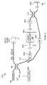
- A schematic diagram of one embodiment of an interferometer according to the present invention is shown in Figure 2 at 100. In this embodiment, the resonant delay circuit utilizes a ring resonator. Light from
source 114 is split bycoupler 116 into two parts in a manner analogous to that described above with respect tointerferometer 10. The first part of the light is applied todevice 12. A portion of the light reflected bydevice 12 is applied tocoupler 122 viacoupler source 114 is applied to a resonantoptical delay circuit 151.Optical delay circuit 151 is constructed from twocouplers optical fiber 154 which is preferably constructed from a material having the same dispersion characteristics as the light signal encounters in traversingfiber 115, phase shifter 11 anddevice 12. -
Optical delay circuit 151 operates as follows. A portion of the light fromcoupler 123 is introduced intofiber loop 154 bycoupler 152 where it makes many traversals offiber loop 154. The remaining portion of light is absorbed by a non-reflecting beam stop at the end offiber 123. Each time the light signal traverses optical fiber 154 a portion of the light exitsfiber loop 154 viacoupler 153 andfiber 155. This light is imaged on a movingmirror 124 vialens 131. The light returning from the moving mirror is applied tocoupler 122 viafiber 156 where it forms the reference signal for the interference. - Each time the light signal in
fiber 154 traverses the fiber, it is attenuated because of losses atcouplers couplers fiber 154 effectively generate a plurality of copies of the reference light signal at ever decreasing intensities. Each successive copy is delayed relative to the previous copy by an amount equal to the delay time offiber loop 154. Hence, for each position ofmirror 124,device 12 is sampled at points separated by optical path length offiber 154. - In practice, there will be numerous reflections from
device 12 corresponding to the various inhomogeneities therein. To determine the exact location of each inhomogeneity,analyzer 129 must be able to identify which "copy" of the reference signal is being compared at any given time. This can be accomplished by including a phase shifter in the recirculating delay loop as shown in Figure 3 at 261. The remaining elements ofinterferometer 200 serve analogous functions to the corresponding elements shown in Figure 2.Phase shifter 261 is similar to phase shifter 111 shown in Figure 2 in that it produces a serrodyne frequency shift on the signal. Each time the circulating light signal passes throughphase shifter 261, the frequency is shifted slightly. Hence, the frequency of the beat signal detected byanalyzer 229 identifies the number of times the reference signal traversedloop 254. This frequency together with the position ofmirror 224 identifies the absolute location of the homogeneity being measured indevice 12. - There are four possible locations for the resonant delay line. The above-described embodiments placed the resonant delay line in the reference arm. This is the preferred location for reasons of sensitivity. It can be shown that there is significantly more signal strength in the reference arm of the interferometer than is needed for obtaining optimal signal to noise ratio. Hence, the loss of intensity causes the least problems in this location. However, it will be apparent to those skilled in the art from the foregoing discussion that the resonant delay line may be located in the source arm (i.e., between
source 214 and coupler 216), the device under test arm (i.e., fiber 215), or the receiver arm (i.e., fiber 220). - Furthermore, it will be apparent that other forms of optical delay may be used. For example, a Fabry-Perot cavity may be used to generate the resonant delay line. A schematic drawing of an embodiment of the present invention utilizing a Fabry-Perot cavity is shown at 300 in Figure 4. The Fabry-Perot cavity is constructed from two partially reflecting
mirrors optical material 367 which preferably has the same dispersion characteristics asdevice 12. Light fromcoupler 316 is imaged onmirror 363 which admits a fraction of the light which bounces betweenmirrors fiber 366 forms the reference beam for the interferometer.Optical isolator 366 prevents light leavingmirror 363 from reachingcoupler 322 viafiber 320.Optical isolator 365 prevents light that is reflected frommirror 324 and returns viacoupler 331 andfiber 366 from re-entering the cavity viamirror 364. The reflectivities ofmirrors pulse reaching coupler 322. - It should be noted that a phase shifter may also be included in
interferometer 300 within the region betweenmirrors phase shifter 261 shown in Figure 3. The phase shifter provides a means foranalyzer 329 to determine the number of times a reference light signal bounces betweenmirrors - The embodiments of the present invention described above utilize a resonant delay with an effectively infinite impulse response. That is, once a light signal enters the delay line, copies are produced for an infinite time with exponentially decreasing intensities. As a result of the differences in intensity of the reference light signals, the signal to noise ratio corresponding to different regions in the device being scanned may be different.
- An alternative delay method having a finite impulse response is shown in Figure 5 at 350.
Delay circuit 350 is constructed from a plurality ofoptical fibers 352 of different lengths. The ends of the fibers are fused together. A light signal entering theinput end 353 is preferably split equally between the various fibers. The various copies of the input light signal are then collected at theoutput end 354. Sincedelay circuit 350 generates a fixed number of equal amplitude copies of the input light signal, each of the corresponding ranges of distances in the device being scanned is treated the same. To allow the identification of the specific delay introduced into each signal, a phase (or frequency) modulator is included in each fiber as shown at 360-363. Each modulator alters the phase (or frequency) of the light by an amount that is unique to the delay experienced by the light in passing through fiber. - The embodiments of the present invention shown in Figures 2-4 have utilized a resonant delay which operates in the transmission mode with a balanced detector for minimizing noise. However, it will be apparent to those skilled in the art that the technique taught in the present invention may also be applied to a Micheleson interferometer. An embodiment of the present invention which is analogous to a Micheleson interferometer is shown in Figure 6 at 400.
Interferometer 400 utilizes a Fabry-Perot cavity to generate the resonant delay in the reference arm of the interferometer. Light fromsource 414 is split bycoupler 416 into two parts. The first part is applied to thedevice 12 under test and the light reflected therefrom returned tocoupler 416 viafiber 415. The second part is applied to the resonant delaygenerator comprising mirrors device 12. Thelight leaving mirror 464 is coupled to a light path includingmoveable mirror 424. This light is returned tocoupler 416 where if provides the reference signal for the interference. Aphase shifter 461 is included betweenmirrors Phase shifter 461 alters the frequency of the light bouncing betweenmirrors phase shifter 461 its frequency is increased slightly. Light isolators 467469 together withcouplers mirror 463 from returning todetector 427. This light signal has sufficient intensity to generate excessive noise indetector 427. - The embodiments of the present invention discussed above utilize a continuous light source and identifies the copy of the reference signal being used by frequency shifting the various copies. Other methods for identifying the copy of the reference signal that is being combined with the reflected light from
device 12 may, however, be used. Referring again to Figure 2, iflight source 114 is pulsed andanalyzer 129 is gated in time, then the time delay between the pulse and the time at which analyzer 129 is gated may be used to select the specific copy of the reference signal used in the interference. - The gating operation may be accomplished by including an optical switch in
fiber path 156 shown in Figure 2. The switch would normally be open. At a predetermined time relative to the light pulse generated bysource 114, the switch would be closed. The speed of the switch would need to be sufficient to assure that no more than one of the copies of the reference signal reachedcoupler 122. It will be apparent to those skilled in the art that the gating could also be accomplished by other switch configurations.
Claims (8)
- An optical interferometer[100,200,300,400] for measuring the optical properties of a device[12], said interferometer comprising: source means[114, 214, 314, 414] for providing a low-coherence light signal; splitting means[116, 216, 316, 416] for dividing said low-coherence light signal into first and second light signals; means[115, 215, 315, 415] for applying a portion of said first light signal to said device[12]; adding means[122, 222, 322, 416] for combining light signals on first and second ports thereof to generate a combined light signal; detection means[132, 232, 332,427] for measuring the amplitude of said combined light signal; means[115, 215, 315, 415] for collecting a portion of the backscattered light generated by the application of said first light signal to said device[12] and for inputting a portion of said collected backscattered light to said first port of said adding means[122, 222, 322, 416]; delay means[151, 251, 351, 350] for generating a sequence of light signals from one of said first or second light signals, each said generated light signal being displaced in time with respect to the previously generated light signal in said sequence; and means[156] for inputting a portion of said generated light signals to said second port of said adding means.
- The interferometer[100,200,300,400] of Claim 1 wherein said delay means[151, 251, 351, 350] further comprises means[124, 224, 324, 424] for varying the difference in the optical path lengths traveled by said backscattered light and said generated light signals before entering said adding means[122, 222, 322, 416].
- The interferometer[100,200,300,400] of Claim 1 wherein said detection means[132, 232, 332,427] further comprises means[261, 461,360, 361, 362, 363] for identifying a specific said delayed light signal in said sequence of delayed light signals.
- The interferometer[100,200,300,400] of Claim 3 wherein said identifying means[261, 461,360, 361, 362, 363] comprises means for altering the frequency or phase of each said generated light signal generated by said delay means relative to the previous said generated light signal in said sequence.
- The interferometer[100,200,300,400] of Claim 3 wherein the portion of said first light signal applied to said device[12] comprises a light pulse and wherein said identifying means comprises means for specifying the time delay between the generation of said light pulse and the time at which said detection means[129, 229, 329, 429] measures said amplitude of said combined light signal.
- The interferometer[100,200,300,400] of Claim 1 wherein said delay means[351] comprises a Fabry-Perot cavity.
- The interferometer[100,200,300,400] of Claim 1 wherein said delay means[151,251] comprises a ring resonator.
- The interferometer[100,200,300,400] of Claim 1 wherein said delay means[350] comprises a plurality of optical fibers of different lengths.
Applications Claiming Priority (2)
| Application Number | Priority Date | Filing Date | Title |
|---|---|---|---|
| US07/907,765 US5268738A (en) | 1992-06-30 | 1992-06-30 | Extended distance range optical low-coherence reflectometer |
| US907765 | 1997-08-08 |
Publications (3)
| Publication Number | Publication Date |
|---|---|
| EP0578400A2 EP0578400A2 (en) | 1994-01-12 |
| EP0578400A3 EP0578400A3 (en) | 1994-01-26 |
| EP0578400B1 true EP0578400B1 (en) | 1996-04-17 |
Family
ID=25424606
Family Applications (1)
| Application Number | Title | Priority Date | Filing Date |
|---|---|---|---|
| EP93304811A Expired - Lifetime EP0578400B1 (en) | 1992-06-30 | 1993-06-21 | Optical low coherence reflectometer with delay sequence |
Country Status (4)
| Country | Link |
|---|---|
| US (1) | US5268738A (en) |
| EP (1) | EP0578400B1 (en) |
| JP (1) | JPH0666517A (en) |
| DE (1) | DE69302232T2 (en) |
Families Citing this family (41)
| Publication number | Priority date | Publication date | Assignee | Title |
|---|---|---|---|---|
| US6134003A (en) * | 1991-04-29 | 2000-10-17 | Massachusetts Institute Of Technology | Method and apparatus for performing optical measurements using a fiber optic imaging guidewire, catheter or endoscope |
| US6111645A (en) | 1991-04-29 | 2000-08-29 | Massachusetts Institute Of Technology | Grating based phase control optical delay line |
| US6501551B1 (en) | 1991-04-29 | 2002-12-31 | Massachusetts Institute Of Technology | Fiber optic imaging endoscope interferometer with at least one faraday rotator |
| US6485413B1 (en) | 1991-04-29 | 2002-11-26 | The General Hospital Corporation | Methods and apparatus for forward-directed optical scanning instruments |
| DE4244605A1 (en) * | 1992-05-27 | 1993-12-02 | Hewlett Packard Co | Optical low-coherence reflectometer with improved sensitivity with optical attenuation |
| US5471300A (en) * | 1994-04-12 | 1995-11-28 | Northrop Grumman Corporation | Apparatus and method for providing a feedback measurement in a laser system |
| JP3453745B2 (en) * | 1995-02-02 | 2003-10-06 | 横河電機株式会社 | Optical fiber inspection equipment |
| US5844235A (en) * | 1995-02-02 | 1998-12-01 | Yokogawa Electric Corporation | Optical frequency domain reflectometer for use as an optical fiber testing device |
| JP3453746B2 (en) * | 1995-02-09 | 2003-10-06 | 横河電機株式会社 | Optical fiber inspection equipment |
| US5557400A (en) * | 1995-02-15 | 1996-09-17 | Hewlett-Packard Company | Multiplexed sensing using optical coherence reflectrometry |
| US5596409A (en) * | 1995-03-22 | 1997-01-21 | Eastman Kodak Company | Associated dual interferometric measurement method for determining a physical property of an object |
| US5659392A (en) * | 1995-03-22 | 1997-08-19 | Eastman Kodak Company | Associated dual interferometric measurement apparatus for determining a physical property of an object |
| US5647032A (en) * | 1995-08-24 | 1997-07-08 | Kowa Company, Ltd. | Interferometers for measuring coherence length and high-speed switching of laser light |
| US6201608B1 (en) | 1998-03-13 | 2001-03-13 | Optical Biopsy Technologies, Inc. | Method and apparatus for measuring optical reflectivity and imaging through a scattering medium |
| EP0947862A3 (en) | 1998-03-31 | 2004-03-17 | Ntt Advanced Technology Corporation | Method and apparatus for maintaining optical signal having low degree of polarization in specific state of polarization |
| US5975697A (en) * | 1998-11-25 | 1999-11-02 | Oti Ophthalmic Technologies, Inc. | Optical mapping apparatus with adjustable depth resolution |
| US6445939B1 (en) | 1999-08-09 | 2002-09-03 | Lightlab Imaging, Llc | Ultra-small optical probes, imaging optics, and methods for using same |
| AU1794101A (en) * | 1999-11-23 | 2001-06-04 | Nanovation Technologies, Inc. | Optical mach-zehnder switch with movable phase shifter |
| US6738144B1 (en) | 1999-12-17 | 2004-05-18 | University Of Central Florida | Non-invasive method and low-coherence apparatus system analysis and process control |
| US6766115B1 (en) * | 2000-08-22 | 2004-07-20 | Agilent Technologies, Inc. | Multiport optical component testing using a single optical receiver |
| JP3423680B2 (en) * | 2000-10-18 | 2003-07-07 | 安藤電気株式会社 | Low coherent reflectometer |
| CA2426714C (en) * | 2000-10-31 | 2010-02-09 | Forskningscenter Riso | Optical amplification in coherent optical frequency modulated continuous wave reflectometry |
| US6728571B1 (en) | 2001-07-16 | 2004-04-27 | Scimed Life Systems, Inc. | Electronically scanned optical coherence tomography with frequency modulated signals |
| JP4472991B2 (en) * | 2002-02-14 | 2010-06-02 | イマラックス・コーポレーション | Target research method and optical interferometer (variant) |
| JP2005532558A (en) * | 2002-07-11 | 2005-10-27 | アジレント・テクノロジーズ・インク | Delay interferometer |
| US7474407B2 (en) * | 2003-02-20 | 2009-01-06 | Applied Science Innovations | Optical coherence tomography with 3d coherence scanning |
| JP3995686B2 (en) * | 2003-05-08 | 2007-10-24 | 富士通株式会社 | Dispersion slope compensator |
| US7388672B2 (en) * | 2004-11-19 | 2008-06-17 | Carl Ziess Meditec, Inc. | High efficiency balanced detection interferometer |
| WO2008013705A2 (en) | 2006-07-26 | 2008-01-31 | Luna Innovations Incorporated | High resolution interferometric optical frequency domain reflectometry ( ofdr) beyond the laser coherence length |
| US7667850B2 (en) * | 2007-06-01 | 2010-02-23 | Raytheon Corporation | Imaging system with low coherence light source |
| GB2451678A (en) * | 2007-08-10 | 2009-02-11 | Sensl Technologies Ltd | Silicon photomultiplier circuitry for minimal onset and recovery times |
| GB0803559D0 (en) * | 2008-02-27 | 2008-04-02 | Univ Kent Canterbury | Multiple path intererometer and method |
| KR101536375B1 (en) * | 2008-06-02 | 2015-07-13 | 스미토모 덴키 고교 가부시키가이샤 | Beam path monitoring device, and beam path monitoring system |
| DE102009050051A1 (en) * | 2009-10-21 | 2011-04-28 | Deutsche Telekom Ag | Method for delaying optical pulses |
| CN102401670A (en) * | 2011-04-06 | 2012-04-04 | 杭州安远科技有限公司 | Fiber optic interferometric system for reducing influence of fiber birefringence |
| US10180496B2 (en) | 2012-11-21 | 2019-01-15 | Nikon Corporation | Laser radar with remote local oscillator |
| US10119816B2 (en) * | 2012-11-21 | 2018-11-06 | Nikon Metrology Nv | Low drift reference for laser radar |
| US9638799B2 (en) | 2012-11-21 | 2017-05-02 | Nikon Corporation | Scan mirrors for laser radar |
| CN103900798B (en) * | 2014-03-28 | 2016-06-29 | 哈尔滨工程大学 | A kind of optical coherence domain polarization measurement device scanning on-line correction with light path |
| CN105115621B (en) * | 2015-06-03 | 2017-11-17 | 闽南师范大学 | The Raman sensing temp measuring system and method for a kind of both-end injection loop configuration |
| CN109782298B (en) * | 2016-04-20 | 2020-06-02 | 安徽大学 | Different-side coupling type microcavity chip type laser self-mixing distance sensing system |
Family Cites Families (1)
| Publication number | Priority date | Publication date | Assignee | Title |
|---|---|---|---|---|
| US5231611A (en) * | 1992-09-09 | 1993-07-27 | The Charles Stark Draper Laboratory, Inc. | Wavelength multiplexed fiber optics resonant ring hydrophone array |
-
1992
- 1992-06-30 US US07/907,765 patent/US5268738A/en not_active Expired - Lifetime
-
1993
- 1993-06-21 DE DE69302232T patent/DE69302232T2/en not_active Expired - Fee Related
- 1993-06-21 EP EP93304811A patent/EP0578400B1/en not_active Expired - Lifetime
- 1993-06-30 JP JP5187178A patent/JPH0666517A/en active Pending
Also Published As
| Publication number | Publication date |
|---|---|
| JPH0666517A (en) | 1994-03-08 |
| DE69302232D1 (en) | 1996-05-23 |
| EP0578400A2 (en) | 1994-01-12 |
| US5268738A (en) | 1993-12-07 |
| DE69302232T2 (en) | 1996-09-19 |
| EP0578400A3 (en) | 1994-01-26 |
Similar Documents
| Publication | Publication Date | Title |
|---|---|---|
| EP0578400B1 (en) | Optical low coherence reflectometer with delay sequence | |
| US5365335A (en) | Optical low-coherence reflectometer using optical attenuation | |
| US5291267A (en) | Optical low-coherence reflectometry using optical amplification | |
| US5268741A (en) | Method and apparatus for calibrating a polarization independent optical coherence domain reflectometer | |
| US5202745A (en) | Polarization independent optical coherence-domain reflectometry | |
| Von Der Weid et al. | On the characterization of optical fiber network components with optical frequency domain reflectometry | |
| Sorin et al. | Measurement of Rayleigh Backscattering at 1.55 mu m with 32 mu m Spatial Resolution | |
| Gilgen et al. | Submillimeter optical reflectometry | |
| JP3290453B2 (en) | Polarization independent type optical coherence area reflection measuring device | |
| JP2954871B2 (en) | Optical fiber sensor | |
| Wiedmann et al. | A generalized approach to optical low-coherence reflectometry including spectral filtering effects | |
| von der Weid et al. | Mid-range coherent optical frequency domain reflectometry with a DFB laser diode coupled to an external cavity | |
| US6211950B1 (en) | Optical pulse reflectometer | |
| JPS63196829A (en) | Method and apparatus for searching fault point of light waveguide | |
| Takada et al. | Optical low coherence reflectometer using [3/spl times/3] fiber coupler | |
| JP3223942B2 (en) | Optical fiber inspection equipment | |
| Sorin | High-resolution optical fiber reflectometry techniques | |
| JPH05322699A (en) | High distance-resolution optical transmission line measuring device | |
| JPH08334436A (en) | Wavelength dispersion measuring method for optical fiber | |
| JPH04225134A (en) | Method and apparatus for measuring reflecting point of optical part | |
| JP3453746B2 (en) | Optical fiber inspection equipment | |
| JPS5837496B2 (en) | Optical fiber length measurement method | |
| JPH0712679A (en) | Method and apparatus for measuring frequency characteristics of optical resonator | |
| Passy et al. | Jaggedness free C-OFDR for optical components characterization | |
| JP2746488B2 (en) | Optical waveguide loss measurement method |
Legal Events
| Date | Code | Title | Description |
|---|---|---|---|
| PUAI | Public reference made under article 153(3) epc to a published international application that has entered the european phase |
Free format text: ORIGINAL CODE: 0009012 |
|
| PUAL | Search report despatched |
Free format text: ORIGINAL CODE: 0009013 |
|
| AK | Designated contracting states |
Kind code of ref document: A2 Designated state(s): DE FR GB |
|
| AK | Designated contracting states |
Kind code of ref document: A3 Designated state(s): DE FR GB |
|
| 17P | Request for examination filed |
Effective date: 19940225 |
|
| 17Q | First examination report despatched |
Effective date: 19950831 |
|
| GRAH | Despatch of communication of intention to grant a patent |
Free format text: ORIGINAL CODE: EPIDOS IGRA |
|
| GRAA | (expected) grant |
Free format text: ORIGINAL CODE: 0009210 |
|
| AK | Designated contracting states |
Kind code of ref document: B1 Designated state(s): DE FR GB |
|
| REF | Corresponds to: |
Ref document number: 69302232 Country of ref document: DE Date of ref document: 19960523 |
|
| ET | Fr: translation filed | ||
| PLBE | No opposition filed within time limit |
Free format text: ORIGINAL CODE: 0009261 |
|
| STAA | Information on the status of an ep patent application or granted ep patent |
Free format text: STATUS: NO OPPOSITION FILED WITHIN TIME LIMIT |
|
| 26N | No opposition filed | ||
| REG | Reference to a national code |
Ref country code: GB Ref legal event code: 732E |
|
| REG | Reference to a national code |
Ref country code: GB Ref legal event code: 732E |
|
| REG | Reference to a national code |
Ref country code: FR Ref legal event code: TP |
|
| REG | Reference to a national code |
Ref country code: FR Ref legal event code: TP |
|
| REG | Reference to a national code |
Ref country code: GB Ref legal event code: IF02 |
|
| PGFP | Annual fee paid to national office [announced via postgrant information from national office to epo] |
Ref country code: DE Payment date: 20070731 Year of fee payment: 15 |
|
| PGFP | Annual fee paid to national office [announced via postgrant information from national office to epo] |
Ref country code: GB Payment date: 20070628 Year of fee payment: 15 |
|
| PGFP | Annual fee paid to national office [announced via postgrant information from national office to epo] |
Ref country code: FR Payment date: 20070618 Year of fee payment: 15 |
|
| GBPC | Gb: european patent ceased through non-payment of renewal fee |
Effective date: 20080621 |
|
| REG | Reference to a national code |
Ref country code: FR Ref legal event code: ST Effective date: 20090228 |
|
| PG25 | Lapsed in a contracting state [announced via postgrant information from national office to epo] |
Ref country code: DE Free format text: LAPSE BECAUSE OF NON-PAYMENT OF DUE FEES Effective date: 20090101 |
|
| PG25 | Lapsed in a contracting state [announced via postgrant information from national office to epo] |
Ref country code: GB Free format text: LAPSE BECAUSE OF NON-PAYMENT OF DUE FEES Effective date: 20080621 |
|
| PG25 | Lapsed in a contracting state [announced via postgrant information from national office to epo] |
Ref country code: FR Free format text: LAPSE BECAUSE OF NON-PAYMENT OF DUE FEES Effective date: 20080630 |