EP0578126A2 - Multi-layered hot water storage tank with countercurrent heat eschanger without external energy source - Google Patents
Multi-layered hot water storage tank with countercurrent heat eschanger without external energy source Download PDFInfo
- Publication number
- EP0578126A2 EP0578126A2 EP93110482A EP93110482A EP0578126A2 EP 0578126 A2 EP0578126 A2 EP 0578126A2 EP 93110482 A EP93110482 A EP 93110482A EP 93110482 A EP93110482 A EP 93110482A EP 0578126 A2 EP0578126 A2 EP 0578126A2
- Authority
- EP
- European Patent Office
- Prior art keywords
- water
- storage tank
- heat exchanger
- hot water
- stratified
- Prior art date
- Legal status (The legal status is an assumption and is not a legal conclusion. Google has not performed a legal analysis and makes no representation as to the accuracy of the status listed.)
- Granted
Links
Images

Classifications
-
- F—MECHANICAL ENGINEERING; LIGHTING; HEATING; WEAPONS; BLASTING
- F28—HEAT EXCHANGE IN GENERAL
- F28D—HEAT-EXCHANGE APPARATUS, NOT PROVIDED FOR IN ANOTHER SUBCLASS, IN WHICH THE HEAT-EXCHANGE MEDIA DO NOT COME INTO DIRECT CONTACT
- F28D20/00—Heat storage plants or apparatus in general; Regenerative heat-exchange apparatus not covered by groups F28D17/00 or F28D19/00
- F28D20/0034—Heat storage plants or apparatus in general; Regenerative heat-exchange apparatus not covered by groups F28D17/00 or F28D19/00 using liquid heat storage material
- F28D20/0039—Heat storage plants or apparatus in general; Regenerative heat-exchange apparatus not covered by groups F28D17/00 or F28D19/00 using liquid heat storage material with stratification of the heat storage material
-
- F—MECHANICAL ENGINEERING; LIGHTING; HEATING; WEAPONS; BLASTING
- F24—HEATING; RANGES; VENTILATING
- F24H—FLUID HEATERS, e.g. WATER OR AIR HEATERS, HAVING HEAT-GENERATING MEANS, e.g. HEAT PUMPS, IN GENERAL
- F24H1/00—Water heaters, e.g. boilers, continuous-flow heaters or water-storage heaters
- F24H1/18—Water-storage heaters
- F24H1/20—Water-storage heaters with immersed heating elements, e.g. electric elements or furnace tubes
- F24H1/208—Water-storage heaters with immersed heating elements, e.g. electric elements or furnace tubes with tubes filled with heat transfer fluid
-
- F—MECHANICAL ENGINEERING; LIGHTING; HEATING; WEAPONS; BLASTING
- F28—HEAT EXCHANGE IN GENERAL
- F28D—HEAT-EXCHANGE APPARATUS, NOT PROVIDED FOR IN ANOTHER SUBCLASS, IN WHICH THE HEAT-EXCHANGE MEDIA DO NOT COME INTO DIRECT CONTACT
- F28D20/00—Heat storage plants or apparatus in general; Regenerative heat-exchange apparatus not covered by groups F28D17/00 or F28D19/00
- F28D2020/0065—Details, e.g. particular heat storage tanks, auxiliary members within tanks
- F28D2020/0069—Distributing arrangements; Fluid deflecting means
-
- F—MECHANICAL ENGINEERING; LIGHTING; HEATING; WEAPONS; BLASTING
- F28—HEAT EXCHANGE IN GENERAL
- F28D—HEAT-EXCHANGE APPARATUS, NOT PROVIDED FOR IN ANOTHER SUBCLASS, IN WHICH THE HEAT-EXCHANGE MEDIA DO NOT COME INTO DIRECT CONTACT
- F28D20/00—Heat storage plants or apparatus in general; Regenerative heat-exchange apparatus not covered by groups F28D17/00 or F28D19/00
- F28D2020/0065—Details, e.g. particular heat storage tanks, auxiliary members within tanks
- F28D2020/0078—Heat exchanger arrangements
-
- Y—GENERAL TAGGING OF NEW TECHNOLOGICAL DEVELOPMENTS; GENERAL TAGGING OF CROSS-SECTIONAL TECHNOLOGIES SPANNING OVER SEVERAL SECTIONS OF THE IPC; TECHNICAL SUBJECTS COVERED BY FORMER USPC CROSS-REFERENCE ART COLLECTIONS [XRACs] AND DIGESTS
- Y02—TECHNOLOGIES OR APPLICATIONS FOR MITIGATION OR ADAPTATION AGAINST CLIMATE CHANGE
- Y02B—CLIMATE CHANGE MITIGATION TECHNOLOGIES RELATED TO BUILDINGS, e.g. HOUSING, HOUSE APPLIANCES OR RELATED END-USER APPLICATIONS
- Y02B10/00—Integration of renewable energy sources in buildings
- Y02B10/50—Hydropower in dwellings
-
- Y—GENERAL TAGGING OF NEW TECHNOLOGICAL DEVELOPMENTS; GENERAL TAGGING OF CROSS-SECTIONAL TECHNOLOGIES SPANNING OVER SEVERAL SECTIONS OF THE IPC; TECHNICAL SUBJECTS COVERED BY FORMER USPC CROSS-REFERENCE ART COLLECTIONS [XRACs] AND DIGESTS
- Y02—TECHNOLOGIES OR APPLICATIONS FOR MITIGATION OR ADAPTATION AGAINST CLIMATE CHANGE
- Y02E—REDUCTION OF GREENHOUSE GAS [GHG] EMISSIONS, RELATED TO ENERGY GENERATION, TRANSMISSION OR DISTRIBUTION
- Y02E60/00—Enabling technologies; Technologies with a potential or indirect contribution to GHG emissions mitigation
- Y02E60/14—Thermal energy storage
Definitions
- Solar collectors are used in most cases for the production of hot industrial water, since here a significant part of the annual energy required for the production of hot water can be covered by solar energy.
- Hot water storage tanks are mostly used to temporarily store the thermal energy collected.
- the present invention relates to a hot water tank that enables stratified loading and unloading without the disadvantages mentioned above.
- the memory according to the invention is preferably operated without pressure, so that e.g. an inexpensive plastic construction is made possible.
- the storage walls must be constructed from a poorly heat-conducting material in order to avoid rapid temperature compensation between the warmer and the colder water layers. This is useful for loading the storage tank with a solar system, e.g. common drainage system in the Netherlands ("drainback system”) (no antifreeze required, good heat transfer in the collector, no solar heat exchanger in the storage tank).
- the water which is preferably circulated by a thermostatically controlled pump, is drawn off from the lower part of the store and, after heating to the desired final temperature, is conducted into the upper part of the store, the laminar layering possibly being ensured by a calming plate.
- the hot water is heated in a heat exchanger in which, in countercurrent to the hot water, the warm water from the upper region of the storage tank is cooled, and is conducted into the lower area of the storage without effort from external energy.
- the heat exchanger is located in the upper area of the storage tank. Cold process water is heated as it flows through the heat exchanger. At the same time, the hot storage water in the vicinity of the heat exchanger is cooled. This cooled storage water now has a greater density, so that a counterflow to the process water through the heat exchanger is set down. An outflow channel is connected to the heat exchanger, which prevents mixing of cooled and hot storage water.
- the heat exchanger is constructed according to claim 3 from a finned tube (1) (preferably copper).
- the finned tube is spirally wound and arranged between two separating surfaces (2), which means that the storage water must flow through the spaces between the fins.
- a finned tube (1) preferably copper
- the finned tube is spirally wound and arranged between two separating surfaces (2), which means that the storage water must flow through the spaces between the fins.
- Guide structures for example an inserted rubber band (see FIG. 2, (3)), are attached between the turns of the finned tube, as a result of which the gap between the fins and separating surfaces is sealed.
- Another possibility according to the invention is according to claims 9 and 10 the use of finned tubes with angular fins or their approximation by bending the edges of round fins.
- the separating surfaces are made of a poorly heat-conducting material, preferably plastic, in order to avoid direct thermal contact between cooler and warmer areas of the heat exchanger and the surrounding hot storage water.
- the cold water connection (4) isolated inside the storage tank is located at the lower end of the finned tube spiral, the hot water outlet (5) at the higher end.
- Storage water that sinks through the heat exchanger from above flows in a countercurrent to the rising process water through the heat exchanger.
- the channel formed by the separating surfaces (2) opens into an outflow channel (6) which is made of a poorly heat-conducting material, preferably a plastic tube.
- the discharge pipe extends up to a few centimeters above the storage floor, where the cooled storage water is layered.
- the cross-section of the outflow channel must not be too large, since between each withdrawal of hot water due to a pressure equalization between the outflow pipe and the rest of the tank, the pipe is filled with hot water according to the layer height in the storage tank. This warm water must be displaced downwards into the cooler storage part each time hot water is removed, which on the one hand hinders the formation of the thermosiphon circuit and on the other hand the stratification in the hot water tank is reduced. If the cross-section of the outflow pipe becomes too small, however, the flow resistance becomes too large, which in turn impairs the thermosiphon circuit.
- the entire heat exchanger is arranged as high as possible in the storage tank so that a thermosiphon flow can still develop even with a largely discharged storage tank with a narrow hot water layer.
- thermodynamically best countercurrent heat exchange is achieved when the pressure loss in the entire heat exchanger is so great that the mean one that arises Storage water flow roughly corresponds to the typical process water flow.
- the storage water could be cooled by approx. 17 K when the storage tank was full and 28 K when the storage tank was almost empty.
- the hot water temperature was initially around 57 ° C and dropped to around 45 ° C towards the end of the discharge.
- FIG. 6 shows a second principle according to the invention, which enables the circulation of storage water free of external energy by means of a counterflow heat exchanger:
- the process water drives a small turbine (10) or a water motor, whereby part of the line pressure is reduced.
- Smallest pump (11) driven, which sends hot storage water from the upper storage area through a counterflow heat exchanger (12), in which the process water is heated and the storage water is cooled.
- the cooled storage water is reintroduced into the lower area of the storage so that it does not mix with warmer layers (eg below a calming plate).
- the direct coupling of the drive unit and the pump and a corresponding dimensioning ensure that the mass flow of the domestic water to be heated and that of the storage water to be cooled are approximately the same for each withdrawal quantity, which is a prerequisite for a thermodynamically optimal countercurrent heat exchange.
- a water pump that operates according to the positive displacement principle with low friction e.g. a gear pump
- a gear pump can be operated in reverse.
- the water motor or turbine and pump are connected to one another by a magnetic coupling.
Abstract
Description
Sonnenkollektoren werden in den meisten Fällen zur Erzeugung von warmem Brauchwasser eingesetzt, da hier auf einfache Weise ein bedeutender Anteil der jährlichen notwendigen Energie zur Erzeugung von Warmwasser durch Sonnenenergie gedeckt werden kann. Zur Zwischenspeicherung der aufgefangenen Wärmeenergie werden meistens Warmwasserspeicher benutzt.Solar collectors are used in most cases for the production of hot industrial water, since here a significant part of the annual energy required for the production of hot water can be covered by solar energy. Hot water storage tanks are mostly used to temporarily store the thermal energy collected.
Wesentlichen Einfluß auf Wirkungs- und Deckungsgrad der Solaranlage hat die Art der Be- und Entladung:
- Bei der durchmischten Beladung wird die Temperatur des gesamten Speichers gleichmäßig angehoben.
- Bei der geschichteten Beladung wird das Wasser des Speichers schichtweise von oben nach unten auf die Endtemperatur gebracht.
- Bei der durchmischten Entladung wird die Temperatur des gesamten Speichers gleichmäßig gesenkt.
- Bei der geschichteten Entladung wird das Wasser des Speichers schichtweise von unten nach oben abgekühlt.
- When the load is mixed, the temperature of the entire storage tank is raised evenly.
- With stratified loading, the water in the storage tank is brought to the final temperature in layers from top to bottom.
- When the discharge is mixed, the temperature of the entire store is reduced evenly.
- With stratified discharge, the water in the storage tank is cooled in layers from bottom to top.
Die geschichtete Be- und Entladung weist insbesondere in Verbindung mit einer Solaranlage oder einer Kraft-Wärme-Kopplung wesentliche Vorteile auf:
- Schnelle Verfügbarkeit bereits nach kurzem Beladevorgang.
- Hohe Wärmekapazität durch große Temperaturspreizung.
- Tiefe Einströmtemperatur für die Solaranlage oder Kraft-Wärme-Kopplungsanlage; dadurch geringe thermische Verluste bei der Solaranlage bzw. guter Wirkungsgrad bei der Erzeugung von Arbeit durch die Wärmekraftmaschine.
- Geringere thermische Verluste als ein durchmischter Speicher mit gleicher gespeicherter Wärme.
- Fast availability after a short loading process.
- High heat capacity due to large temperature spread.
- Low inflow temperature for the solar system or combined heat and power system; thereby low thermal losses in the solar system or good efficiency in the production of work by the heat engine.
- Lower thermal losses than a mixed storage with the same stored heat.
In den meisten Anwendungen im Privathausbereich werden heute allerdings Warmwasserspeicher mit durchmischter Beladung, oftmals auch mit durchmischter Entladung eingesetzt. Die heute bekannten Techniken zur Realisierung der geschichteten Be- und Entladung bringen nämlich jeweils auch entscheidende Nachteile mit sich:
- Bei der direkten Be- und Entladung steht das Trinkwasser im Speichertank, mit Temperaturen, die zwischen der des Kaltwassers und der Warmwasser-Endtemperatur liegen. Dadurch treten verstärkt hygienische Probleme, wie z.B. Legionellenwachstum, auf. Außerdem erfordert diese Technik einen (relativ teuren) Druckspeicher. In Gegenden mit Frostgefahr kann diese Technik nicht in Verbindung mit einer Solaranlage eingesetzt werden.
- Um die Hygieneprobleme zu umgehen, wird zur geschichteten Speicherentladung gelegentlich ein externer Wärmetauscher eingesetzt. Dies ist allerdings im Vergleich zu einem im Speicher eingebauten Durchlauferhitzer (mit durchmischter Entladung) wegen der hierfür notwendigen zusätzlichen Installation (Umwälzpumpe, Regelung) relativ aufwendig.
- Wegen Einfriergefahr wird in nördlichen Ländern eine Solaranlage meist in einem Sekundärkreis mit Frostschutzmittel und im unteren Bereich des Speichers angebrachtem Solar-Wärmetauscher betrieben. Stand der Technik zur geschichteten Beladung ist auch hier, stattdessen einen externen Wärmetauscher einzusetzen, der allerdings ebenso den oben erwähnten Zusatzaufwand mit sich bringt.
- During direct loading and unloading, the drinking water is in the storage tank, with temperatures that lie between that of the cold water and the hot water end temperature. This increases hygienic problems, such as legionella growth. This technique also requires a (relatively expensive) pressure accumulator. In areas where there is a risk of frost, this technology cannot be used in conjunction with a solar system.
- To avoid the hygiene problems, an external heat exchanger is occasionally used for stratified storage discharge. However, this is relatively expensive in comparison to a water heater installed in the storage tank (with mixed discharge) because of the additional installation (circulation pump, control) required for this.
- Due to the risk of freezing, a solar system in northern countries is usually operated in a secondary circuit with antifreeze and a solar heat exchanger installed in the lower area of the storage tank. The state of the art for stratified loading is to use an external heat exchanger instead, but this also entails the additional effort mentioned above.
Die vorliegende Erfindung betrifft einen Warmwasserspeicher, der die geschichtete Be- und Entladung ermöglicht, ohne die oben genannten Nachteile nach sich zu ziehen.The present invention relates to a hot water tank that enables stratified loading and unloading without the disadvantages mentioned above.
Der erfindungsgemäße Speicher wird vorzugsweise drucklos betrieben, wodurch z.B. eine kostengünstige Kunststoffbauweise ermöglicht wird. Insbesondere bei kleinen Speichern müssen die Speicherwände aus einem schlecht wärmeleitenden Material aufgebaut sein, um einen schnellen Temperaturausgleich zwischen der wärmeren und der kälteren Wasserschicht zu vermeiden. Zur Beladung des Speichers mit einer Solaranlage bietet sich das z.B. in Holland allgemein verbreitete Entleer-/Auffangsystem ("Drainback-System") an (kein Frostschutzmittel nötig, guter Wärmeübergang im Kollektor, kein Solar-Wärmetauscher im Speicher).The memory according to the invention is preferably operated without pressure, so that e.g. an inexpensive plastic construction is made possible. In the case of small storage tanks in particular, the storage walls must be constructed from a poorly heat-conducting material in order to avoid rapid temperature compensation between the warmer and the colder water layers. This is useful for loading the storage tank with a solar system, e.g. common drainage system in the Netherlands ("drainback system") (no antifreeze required, good heat transfer in the collector, no solar heat exchanger in the storage tank).
Das vorzugsweise durch eine thermostatisch geregelte Pumpe umgewälzte Wasser wird vom unteren Teil des Speichers abgezogen und nach der Erwärmung auf die gewünschte Endtemperatur in den oberen Teil des Speichers geleitet, wobei die laminare Einschichtung eventuell durch eine Beruhigungsplatte gewährleistet wird.The water, which is preferably circulated by a thermostatically controlled pump, is drawn off from the lower part of the store and, after heating to the desired final temperature, is conducted into the upper part of the store, the laminar layering possibly being ensured by a calming plate.
Die Erwärmung des Brauchwassers erfolgt erfindungsgemäß in einem Wärmetauscher, in dem im Gegenstrom zum Brauchwasser das warme Wasser aus dem oberen Bereich des Speichers abgekühlt, und ohne Aufwand von Fremdenergie in den unteren Bereich des Speichers geleitet wird. Dies wird erfindungsgemäß durch zwei alternative Techniken erreicht:According to the invention, the hot water is heated in a heat exchanger in which, in countercurrent to the hot water, the warm water from the upper region of the storage tank is cooled, and is conducted into the lower area of the storage without effort from external energy. According to the invention, this is achieved by two alternative techniques:
Der Wärmetauscher ist im oberen Bereich des Speichers angeordnet. Kaltes Brauchwasser wird beim Durchströmen des Wärmetauschers erwärmt. Gleichzeitig wird das heiße Speicherwasser in der Umgebung des Wärmetauschers abgekühlt. Dieses abgekühlte Speicherwasser hat nun eine größere Dichte, so daß sich eine Gegenströmung zum Brauchwasser durch den Wärmetauscher nach unten einstellt. An den Wärmetauscher schließt sich ein Abströmkanal an, wodurch eine Vermischung von abgekühltem und heißem Speicherwasser vermieden wird.The heat exchanger is located in the upper area of the storage tank. Cold process water is heated as it flows through the heat exchanger. At the same time, the hot storage water in the vicinity of the heat exchanger is cooled. This cooled storage water now has a greater density, so that a counterflow to the process water through the heat exchanger is set down. An outflow channel is connected to the heat exchanger, which prevents mixing of cooled and hot storage water.
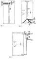
In Figur 1 und 2 ist der Gesamtaufbau des Wärmetauschers dargestellt:
Der Wärmetauscher wird nach Anspruch 3 aus einem Ripprohr (1) (vorzugsweise Kupfer) aufgebaut. Das Ripprohr ist spiralförmig gewunden und zwischen zwei Trennflächen (2) angeordnet, wodurch erreicht wird, daß das Speicherwasser durch die Zwischenräume zwischen den Rippen strömen muß. Um eine möglichst gleichmäßige Durchströmung der Rippen auch in der Nähe des Kernrohres zu bewirken, sind vorteilhafterweise Leitstrukturen, z.B. ein eingelegtes Gummiband (siehe Figur 2, (3)), zwischen den Windungen des Ripprohres angebracht, wodurch gleichzeitig der Spalt zwischen Rippen und Trennflächen abgedichtet wird. Eine andere erfindungsgemäße Möglichkeit stellt gemäß den Ansprüchen 9 und 10 der Einatz von Ripprohren mit eckigen Rippen dar oder deren Anäheung durch Umbiegen der Ränder runder Rippen.The overall construction of the heat exchanger is shown in FIGS. 1 and 2:
The heat exchanger is constructed according to
Die Trennflächen sind aus einem schlecht wärmeleitenden Material, vorzugsweise aus Kunststoff, aufgebaut, um einen direkten thermischen Kontakt zwischen kühleren und wärmeren Bereichen des Wärmetauschers und zum umgebenden heißen Speicherwasser zu vermeiden. Der innerhalb des Speichers isolierte Kaltwasseranschluß (4) befindet sich am tiefer gelegenen Ende der Ripprohrspirale, der Warmwasserausgang (5) am höher gelegenen Ende. Speicherwasser das von oben durch den Wärmetauscher absinkt, strömt auf diese Weise im Kreuzgegenstrom zum aufsteigenden Brauchwasser durch den Wärmetauscher. Der durch die Trennflächen (2) gebildete Kanal mündet in einen Abströmkanal (6), der aus einem schlecht wärmeleitenden Material, vorzugsweise aus einem Kunststoffrohr, aufgebaut ist. Das Abströmrohr reicht bis wenige Zentimeter über den Speicherboden, wo das abgekühlte Speicherwasser eingeschichtet wird.The separating surfaces are made of a poorly heat-conducting material, preferably plastic, in order to avoid direct thermal contact between cooler and warmer areas of the heat exchanger and the surrounding hot storage water. The cold water connection (4) isolated inside the storage tank is located at the lower end of the finned tube spiral, the hot water outlet (5) at the higher end. Storage water that sinks through the heat exchanger from above flows in a countercurrent to the rising process water through the heat exchanger. The channel formed by the separating surfaces (2) opens into an outflow channel (6) which is made of a poorly heat-conducting material, preferably a plastic tube. The discharge pipe extends up to a few centimeters above the storage floor, where the cooled storage water is layered.
Der Querschnitt des Abströmkanals darf nicht zu groß sein, da zwischen jeder Entnahme von Warmwasser auf Grund eines Druckausgleichs zwischen dem Abströmrohr und dem restlichen Tank das Rohr mit Warmwasser entsprechend der Schichthöhe im Speicher gefüllt wird. Dieses warme Wasser muß bei jeder erneuten Warmwasserentnahme nach unten in den kühleren Speicherteil verdrängt werden, wodurch zum einen die Ausbildung des Thermosiphonkreislaufes behindert wird, zum anderen die Schichtung im Warmwasserspeicher abgebaut wird. Wird der Querschnitt des Abströmrohres allerdings zu klein, so wird der Strömungswiderstand zu groß, wodurch wiederum der Thermosiphonkreislauf behindert wird.The cross-section of the outflow channel must not be too large, since between each withdrawal of hot water due to a pressure equalization between the outflow pipe and the rest of the tank, the pipe is filled with hot water according to the layer height in the storage tank. This warm water must be displaced downwards into the cooler storage part each time hot water is removed, which on the one hand hinders the formation of the thermosiphon circuit and on the other hand the stratification in the hot water tank is reduced. If the cross-section of the outflow pipe becomes too small, however, the flow resistance becomes too large, which in turn impairs the thermosiphon circuit.
Der gesamte Wärmetauscher ist möglichst weit oben im Speicher angeordnet, damit sich auch bei einem weitgehend entladenen Speicher mit einer schmalen Heißwasserschicht eine Thermosiphonströmung noch ausbilden kann. Gleichzeitig wird ein Gegenstromwärmeaustausch umso besser erreicht, je höher die Anzahl der Ripprohrwindungen ist, wobei andererseits auch hier der Strömungswiderstand nicht zu hoch werden darf.The entire heat exchanger is arranged as high as possible in the storage tank so that a thermosiphon flow can still develop even with a largely discharged storage tank with a narrow hot water layer. At the same time, the higher the number of finned tube windings, the better the countercurrent heat exchange is achieved, but on the other hand the flow resistance must not be too high here either.
Der thermodynamisch beste Gegenstrom-Wärmeaustausch wird dann erreicht, wenn der Druckverlust im gesamten Wärmetauscher so groß ist, daß der sich einstellende mittlere Speicherwasserstrom ungefähr dem typischen Brauchwasserstrom entspricht.The thermodynamically best countercurrent heat exchange is achieved when the pressure loss in the entire heat exchanger is so great that the mean one that arises Storage water flow roughly corresponds to the typical process water flow.
In Figur 1 bis 4 sind beispielhaft drei erfindungsgemäße Anordnungen, die den oben genannten Bedingungen gerecht werden, dargestellt:
- In Figur 1 und 2 ist das Ripprohr in Form einer kegelförmigen Spirale gewunden; die kegelförmigen Trennflächen münden in das Abströmrohr. An der tiefsten Stelle der Trennkegel ist ein zum Strömungskanal dichter Durchbruch (7) zwischen der Unter- und der Oberseite des Wärmetauschers vorgesehen, damit auch das anfangs heiße Wasser innerhalb des Wärmetauscherkegels durch die aufsteigende Schicht kalten Wassers verdrängt werden kann und umgekehrt das kalte Wasser bei Speicherbeladung abströmen kann.
- In
Figur 3 ist das Ripprohr zylinderförmig gewunden. Auch hier ist ein Durchbruch zwischen Unter- und Oberseite der Trennflächen erforderlich, falls das Wasservolumen innerhalb des Wärmetauscher-Zylinders genutzt werden soll. - In
Figur 4 ist das Ripprohr in Form einer horizontalen Spirale gewunden, an die sich eine oder mehrere vertikale Windungen anschließen, um den Thermosiphonkreislauf in der Startphase anzuregen.
- In Figures 1 and 2, the finned tube is wound in the form of a conical spiral; the conical partitions open into the outflow pipe. At the lowest point of the separating cone there is an opening (7) which is sealed to the flow channel between the bottom and the top of the heat exchanger, so that the initially hot water inside the heat exchanger cone can be displaced by the rising layer of cold water and vice versa the cold water Memory load can flow out.
- In Figure 3 the finned tube is wound in a cylindrical shape. Here, too, a breakthrough between the top and bottom of the separating surfaces is required if the water volume within the heat exchanger cylinder is to be used.
- In FIG. 4, the finned tube is wound in the form of a horizontal spiral, which is followed by one or more vertical windings in order to stimulate the thermosiphon circuit in the starting phase.
Durch Versuche wurden aus dem komplexen Zusammenspiel der unterschiedlichen Parameter günstige Dimensionierungen des Systems ermittelt. Im folgenden wird als Beispiel die Dimensionierung für einen Warmwasserspeicher mit ca. 500 l Speicherinhalt (Höhe: ca. 1,5 m), einer Heißwassertemperatur im Speicher von ca. 65° C, einer Kaltwassertemperatur von ca. 7° C und einer typischen Entnahmemenge von 10 l/min gegeben, bei der ein standardmäßig verfügbares Ripprohr eingesetzt wird:
- Kupfer-Ripprohr mit Innendurchmesser 10 mm, Außendurchmesser 12 mm,
Ripphöhe 4,5 mm, Rippabstand 1,75 mm, Gesamtlänge: 6 m. - Trichterförmige Anordnung mit 9 Windungen, oberer Durchmesser 300 mm.
- Innendurchmesser des Abströmrohres 50 mm.
- Copper finned tube with inner diameter 10 mm, outer diameter 12 mm, rib height 4.5 mm, rib spacing 1.75 mm, total length: 6 m.
- Funnel-shaped arrangement with 9 turns, upper diameter 300 mm.
- Inner diameter of the discharge pipe 50 mm.
Mit dieser Anordnung konnte eine Abkühlung des Speicherwassers um ca. 17 K bei vollem Speicher und 28 K bei fast leerem Speicher erreicht werden. Die Brauchwassertemperatur lag anfangs bei ca. 57° C und sank gegen Ende der Entladung auf ca. 45° C ab.With this arrangement, the storage water could be cooled by approx. 17 K when the storage tank was full and 28 K when the storage tank was almost empty. The hot water temperature was initially around 57 ° C and dropped to around 45 ° C towards the end of the discharge.
Dies entspricht einer ca. 2,5 fachen Speicherkapazität gegenüber dem gleichen Speicher mit der gleichen Anfangstemperatur, dem gleichen Wärmetauscher, jedoch gemischter Entladung, bei einer Nutztemperatur von 45° C.This corresponds to approx. 2.5 times the storage capacity compared to the same storage tank with the same starting temperature, the same heat exchanger, but mixed discharge, at a useful temperature of 45 ° C.
Computersimulationen zeigen, daß noch günstigere Systemdimensionierungen möglich sind.Computer simulations show that even cheaper system dimensions are possible.
Das gleiche Wärmetauscherprinzip ist nach den Ansprüchen 4 und 5 auch für eine geschichtete Speicherbeladung einsetzbar. Hierbei wird die gesamte Anordnung umgekehrt in dem Speicher angebracht (siehe Figur 5), so daß sich der Wärmetauscher im unteren Speicherbereich befindet und das in diesem Fall "Aufströmkanal" genannte Rohr bis wenige Zentimeter unter die obere Speicherbewandung bzw. die Wasseroberfläche reicht.The same heat exchanger principle can also be used for a stratified storage tank loading according to
In Figur 6 ist ein zweites erfindungsgemäßes Prinzip, das die fremdenergiefreie Umwälzung von Speicherwasser durch einen Gegenstromwärmetauscher ermöglicht, dargestellt:
Das Brauchwasser treibt eine Kleinstturbine (10) oder einen Wassermotor an, wodurch ein Teil des Leitungsdruckes abgebaut wird. Durch die Turbine bzw. den Wassermotor wird eine Kleinstpumpe (11) angetrieben, welche heißes Speicherwasser aus dem oberen Speicherbereich durch einen Gegenstromwärmetauscher (12) schickt, in dem das Brauchwasser erwärmt und das Speicherwasser abgekühlt wird. Das abgekühlte Speicherwasser wird in den unteren Bereich des Speichers wieder so eingeleitet, daß keine Vermischung mit wärmeren Schichten stattfindet (z.B. unterhalb einer Beruhigungsplatte).FIG. 6 shows a second principle according to the invention, which enables the circulation of storage water free of external energy by means of a counterflow heat exchanger:
The process water drives a small turbine (10) or a water motor, whereby part of the line pressure is reduced. Through the turbine or the water motor Smallest pump (11) driven, which sends hot storage water from the upper storage area through a counterflow heat exchanger (12), in which the process water is heated and the storage water is cooled. The cooled storage water is reintroduced into the lower area of the storage so that it does not mix with warmer layers (eg below a calming plate).
Durch die direkte Kopplung von Antriebseinheit und Pumpe und eine entsprechende Dimensionierung wird erreicht, daß der Massenstrom des zu erwärmenden Brauchwassers und der des abzukühlenden Speicherwassers bei jeder Entnahmemenge ungefähr gleich groß sind, was Voraussetzung für einen thermodynamisch optimalen Gegenstrom-Wärmeaustausch ist.The direct coupling of the drive unit and the pump and a corresponding dimensioning ensure that the mass flow of the domestic water to be heated and that of the storage water to be cooled are approximately the same for each withdrawal quantity, which is a prerequisite for a thermodynamically optimal countercurrent heat exchange.
Als Wassermotor läßt sich erfindungsgemäß eine nach dem Verdrängerprinzip arbeitende Pumpe mit geringer Reibung (z.B. eine Zahnradpumpe) umgekehrt betreiben.According to the invention, a water pump that operates according to the positive displacement principle with low friction (e.g. a gear pump) can be operated in reverse.
Um Reibungsverluste durch Dichtungen zu vermeiden, werden Wassermotor bzw. Turbine und Pumpe erfindungsgemäß durch eine Magnetkopplung miteinander verbunden.In order to avoid friction losses due to seals, the water motor or turbine and pump are connected to one another by a magnetic coupling.
Claims (18)
dadurch gekennzeichnet,
daß die Umwälzung des Speicherwassers durch den Wärmetauscher ohne Einsatz von Fremdenergie erfolgt.Stratified hot water storage tank with counterflow heat exchanger for stratified loading or unloading of the storage tank,
characterized,
that the circulation of the storage water through the heat exchanger takes place without the use of external energy.
dadurch gekennzeichnet,
daß der Wärmetauscher im oberen Bereich des Speichers angeordnet ist, so daß kaltes Brauchwasser beim Durchströmen des Wärmetauschers erwärmt wird und gleichzeitig heißes Speicherwasser in der Umgebung des Wärmetauschers abgekühlt wird, wodurch dieses abgekühlte Speicherwasser durch einen sich an den Wärmetauscher anschließenden, bis wenige Zentimeter über den Speicherboden reichenden Abströmkanal absinkt, so daß sich eine Gegenströmung zum Brauchwasser durch den Wärmetauscher einstellt.Hot water stratified storage tank according to claim 1 for stratified discharge of the storage tank,
characterized,
that the heat exchanger is arranged in the upper area of the storage so that cold process water is heated as it flows through the heat exchanger and at the same time hot storage water is cooled in the vicinity of the heat exchanger, whereby this cooled storage water is connected to the heat exchanger by a few centimeters above the Outflow channel reaching the storage floor drops, so that a counterflow to the process water through the heat exchanger is established.
dadurch gekennzeichnet,
daß der Wärmetauscher aus einem spiralförmig gewundenen Ripprohr (1) mit mindestens drei Windungen aufgebaut ist, dessen innerhalb des Speichers isolierter Kaltwasseranschluß (4) sich an dem tiefer gelegenen Ende der Ripprohrspirale befindet und dessen Warmwasserausgang (5) am höher gelegenen Ende liegt, außerdem dadurch gekennzeichnet, daß das Ripprohr zwischen zwei Trennflächen (2) so angeordnet ist, daß das Speicherwasser durch die Zwischenräume zwischen den Rippen im Kreuzgegenstrom zum aufsteigenden Brauchwasser durch den Wärmetauscher strömen muß, wobei der durch die Trennfläche gebildete Kanal in den Abströmkanal (6) mündet, und Abströmkanal sowie Trennflächen aus einem schlecht wärmeleitenden Material aufgebaut sind.Hot water stratified tank according to claim 2,
characterized,
that the heat exchanger is constructed from a spirally wound finned tube (1) with at least three turns, whose insulated cold water connection (4) is located at the lower end of the finned tube spiral and whose hot water outlet (5) is at the higher end, further characterized in that the finned tube is arranged between two separating surfaces (2) in such a way that the stored water through the spaces between the ribs in cross-counterflow to the rising process water through the heat exchanger, the channel formed by the separating surface opens into the outflow channel (6), and the outflow channel and separating surfaces are made of a poorly heat-conducting material.
dadurch gekennzeichnet,
daß der Wärmetauscher im unteren Bereich des Speichers angeordnet ist, so daß heiße Flüssigkeit des Sekundärkreislaufs beim Durchströmen des Wärmetauschers abgekühlt wird und gleichzeitig kaltes Speicherwasser in der Umgebung des Wärmetauschers erwärmt wird, wodurch dieses erwärmte Speicherwasser durch einen sich an den Wärmetauscher anschließenden, bis wenige Zentimeter unter die obere Speicherbewandung bzw. die Wasseroberfläche reichenden Aufströmkanal aufsteigt, so daß sich eine Gegenströmung zum Sekundärkreislauf durch den Wärmetauscher einstellt.Hot water stratified storage tank according to claim 1 for stratified loading of the storage tank,
characterized,
that the heat exchanger is arranged in the lower region of the storage so that hot liquid of the secondary circuit is cooled as it flows through the heat exchanger and at the same time cold storage water is heated in the vicinity of the heat exchanger, whereby this heated storage water is connected to the heat exchanger by up to a few centimeters rises below the upper storage wall or the water surface reaching the inflow channel, so that a counterflow to the secondary circuit through the heat exchanger occurs.
dadurch gekennzeichnet,
daß der Wärmetauscher aus einem spiralförmig gewundenen Ripprohr (1) mit mindestens drei Windungen aufgebaut ist, dessen innerhalb des Speichers isolierter Anschluß für das heiße Wärmeträgermedium (8) sich an dem höher gelegenen Ende der Ripprohrspirale befindet und dessen Ausgang für das abgekühlte Wärmeträgermedium (9) am tiefer gelegenen Ende liegt, außerdem dadurch gekennzeichnet, daß das Ripprohr zwischen zwei Trennflächen (2) so angeordnet ist, daß das Speicherwasser durch die Zwischenräume zwischen den Rippen im Kreuzgegenstrom zum abströmenden Sekundärkreislauf durch den Wärmetauscher strömen muß, wobei der durch die Trennflächen gebildete Kanal in den Aufströmkanal (6) mündet, und Aufströmkanal sowie Trennflächen aus einem schlecht wärmeleitenden Material aufgebaut sind.Hot water stratified storage tank according to claim 4,
characterized,
that the heat exchanger is constructed from a spirally wound finned tube (1) with at least three turns, the connection for the hot heat transfer medium (8) which is insulated within the store is located at the higher end of the finned tube spiral and the outlet for the cooled heat transfer medium (9) is located at the lower end, further characterized in that the finned tube is arranged between two dividing surfaces (2) so that the storage water must flow through the spaces between the fins in a cross-countercurrent to the outflowing secondary circuit through the heat exchanger, the channel formed by the dividing surfaces opens into the upflow channel (6), and upflow channel and separating surfaces are made of a poorly heat-conducting material.
dadurch gekennzeichnet,
daß der Druckverlust im gesamten Wärmetauscher ungefähr so groß ist, daß der sich einstellende mittlere Speicherwasserstrom ungefähr dem typischen Brauchwasserstrom entspricht, bzw., bei Flüssigkeiten mit unterschiedlichen Wärmekapazitäten, daß sich die Produkte aus Massenstrom und spezifischer Wärmekapazität ungefähr entsprechen.Hot water stratified storage tank according to claims 2 to 5,
characterized,
that the pressure loss in the entire heat exchanger is approximately so large that the resulting average storage water flow corresponds approximately to the typical process water flow, or, for liquids with different heat capacities, that the products of mass flow and specific heat capacity approximately correspond.
dadurch gekennzeichnet,
daß zwischen den Windungen des Ripprohres außen und innen Leitstrukturen angebracht sind, die eine möglichst gleichmäßige Durchströmung der Rippen auch in der Nähe des Kernrohres bewirken und gleichzeitig den Spalt zwischen Rippen und Trennflächen abdichten.Hot water stratified storage tank according to claims 3, 5 and 6,
characterized,
that between the turns of the finned tube outside and inside guide structures are attached, which cause a flow as even as possible through the fins in the vicinity of the core tube and at the same time seal the gap between the fins and separating surfaces.
dadurch gekennzeichnet,
daß die Leitstrukturen durch zwischen die Windungen eingelegte Gummischnüre verwirklicht werden.Hot water stratified tank according to claim 7,
characterized,
that the guide structures are realized by rubber cords inserted between the turns.
dadurch gekennzeichnet,
daß Ripprohre mit eckigen, den Kanal bis zu den Wänden gleichmäßig ausfüllenden Rippen eingesetzt werden.Hot water stratified storage tank according to claims 3, 5 and 6,
characterized,
that finned tubes with angular fins that fill the channel evenly up to the walls are used.
dadurch gekennzeichnet,
daß Ripprohre mit runden Rippen eingesetzt werden, deren Ränder an den Stellen, an denen sie an den Trennflächen anliegen, um 90° abgewinkelt sind.Hot water stratified storage tank according to claims 3, 5 and 6,
characterized,
that finned tubes with round fins are used, the edges of which are angled by 90 ° at the points where they abut the separating surfaces.
dadurch gekennzeichnet,
daß die Ripprohrspirale kegelförmig angeordnet ist.Hot water stratified storage tank according to claims 3 and 5 to 10,
characterized,
that the finned tube spiral is arranged conically.
dadurch gekennzeichnet,
daß die Ripprohrspirale zylinderförmig angeordnet ist, mit keiner, einer oder mehreren sich unten anschließenden horizontalen oder kegelförmigen Windungen.Hot water stratified storage tank according to claims 3 and 5 to 10,
characterized,
that the finned tube spiral is arranged in a cylindrical shape, with no, one or more horizontal or conical turns adjoining at the bottom.
dadurch gekennzeichnet,
daß an der tiefsten Stelle der Trennflächen ein zum Strömungskanal dichter Durchbruch (7) zwischen der Unter- und der Oberseite des Wärmetauschers vorgesehen ist.Hot water stratified storage tank according to claims 11 and 12,
characterized,
that at the deepest point of the separating surfaces there is an opening (7) which is sealed to the flow channel between the bottom and the top of the heat exchanger.
dadurch gekennzeichnet,
daß das Ripprohr in Form einer horizontalen Spirale gewunden ist, an die sich eine oder mehrere vertikale oder kegelförmige Windungen anschließen.Hot water stratified storage tank according to claims 3 and 5 to 10,
characterized,
that the finned tube is wound in the form of a horizontal spiral, which is followed by one or more vertical or conical turns.
dadurch gekennzeichnet,
daß das Brauchwasser eine Kleinstturbine oder einen Wassermotor antreibt, wodurch ein Teil des Leitungsdruckes abgebaut wird, und die Turbine bzw. der Wassermotor eine Kleinstpumpe antreibt, welche heißes Speicherwasser durch einen Gegenstromwärmetauscher schickt, in dem das Brauchwasser erwärmt und das Speicherwasser abgekühlt wird, um das abgekühlte Speicherwasser in den kühleren Bereich des Speichers wieder einzuleiten.Hot water stratified storage tank according to claim 1 for stratified discharge of the storage tank,
characterized,
that the process water drives a miniature turbine or a water motor, which reduces part of the line pressure, and the turbine or the water motor drives a miniature pump, which sends hot storage water through a counterflow heat exchanger in which the process water is heated and the storage water is cooled to prevent this return cooled storage water to the cooler area of the storage.
dadurch gekennzeichnet,
daß Antriebseinheit und Pumpe so dimensioniert sind, daß der Massenstrom des zu erwärmenden Brauchwassers und der des abzukühlenden Speicherwassers bei jeder Entnahmemenge ungefähr gleich groß sind.Hot water stratified storage tank according to claim 15,
characterized,
that the drive unit and pump are dimensioned such that the mass flow of the domestic water to be heated and that of the storage water to be cooled are approximately the same for each withdrawal quantity.
dadurch gekennzeichnet,
daß als Wassermotor eine nach dem Verdrängerprinzip arbeitende Pumpe mit geringer Reibung (z.B. eine Zahnradpumpe) umgekehrt betrieben wird.Hot water stratified storage tank according to claims 15 and 16,
characterized,
that as a water motor, a pump operating on the displacement principle with low friction (for example a gear pump) is operated in reverse.
dadurch gekennzeichnet,
daß Wassermotoren bzw. Turbinen und Pumpe durch eine Magnetkopplung miteinander verbunden sind.Hot water stratified storage tank according to claims 15 to 17,
characterized,
that water motors or turbines and pumps are connected to each other by a magnetic coupling.
Applications Claiming Priority (2)
| Application Number | Priority Date | Filing Date | Title |
|---|---|---|---|
| DE4221668A DE4221668C2 (en) | 1992-07-02 | 1992-07-02 | Hot water stratified storage tank with counterflow heat exchanger |
| DE4221668 | 1992-07-02 |
Publications (3)
| Publication Number | Publication Date |
|---|---|
| EP0578126A2 true EP0578126A2 (en) | 1994-01-12 |
| EP0578126A3 EP0578126A3 (en) | 1994-12-28 |
| EP0578126B1 EP0578126B1 (en) | 1998-05-13 |
Family
ID=6462286
Family Applications (1)
| Application Number | Title | Priority Date | Filing Date |
|---|---|---|---|
| EP93110482A Expired - Lifetime EP0578126B1 (en) | 1992-07-02 | 1993-07-01 | Multi-layered hot water storage tank with countercurrent heat exchanger without external energy source |
Country Status (3)
| Country | Link |
|---|---|
| EP (1) | EP0578126B1 (en) |
| AT (1) | ATE166148T1 (en) |
| DE (2) | DE4221668C2 (en) |
Cited By (8)
| Publication number | Priority date | Publication date | Assignee | Title |
|---|---|---|---|---|
| DE4443715A1 (en) * | 1994-12-09 | 1996-06-13 | Solvis Solarsysteme Gmbh | Water heater |
| DE19710803C2 (en) * | 1997-03-17 | 1999-09-02 | Wagner & Co Solartechnik Gmbh | Hot water storage system |
| AT412740B (en) * | 2003-03-25 | 2005-06-27 | Seebacher Theodor | DEVICE FOR HEATING A LIQUID, E. HOT WATER |
| EP1772676A2 (en) * | 2005-10-10 | 2007-04-11 | Hebert Ganglberger | Heat exchange installation |
| EP2031312A2 (en) * | 2007-08-31 | 2009-03-04 | Johann Kalkgruber | Device for heating domestic water during flow-through |
| EP2407663A2 (en) | 2010-07-13 | 2012-01-18 | SOLARFOCUS Holding GmbH | Control system for water turbine |
| DE10232700B4 (en) * | 2002-07-15 | 2012-06-14 | Frank Meyer zur Heide | Aqua Re energy funnel |
| EP2489945A3 (en) * | 2011-02-18 | 2014-01-22 | Robert Laabmayr | Heat accumulator |
Families Citing this family (11)
| Publication number | Priority date | Publication date | Assignee | Title |
|---|---|---|---|---|
| DE19516837C2 (en) * | 1995-05-08 | 1998-07-16 | Winfried Hesse | Container with a liquid for heat or cold storage |
| DE19703722C2 (en) * | 1997-01-22 | 1999-06-10 | Zenit Energietechnik Gmbh | Pressureless hot water storage made of plastic for solar heating technology |
| DE19703724C2 (en) * | 1997-01-22 | 1999-06-10 | Zenit Energietechnik Gmbh | Pressureless hot water storage made of plastic for solar heating technology |
| DE10121842C2 (en) * | 2001-05-05 | 2003-10-02 | Consolar Energiespeicher Und R | Discharge heat exchanger for heat storage |
| DE102004031789A1 (en) * | 2004-07-01 | 2005-11-03 | Robert Bosch Gmbh | Hot water heating system, with primary and secondary heat transfer units, has a single recirculating pump and a pump drive for the secondary circuit powered by the water flow in the heating circuit |
| DE102004048884B4 (en) * | 2004-10-06 | 2013-11-14 | Frank Triesch | Heat exchanger |
| DE102010004984A1 (en) * | 2010-01-19 | 2011-07-21 | IVT Installations- und Verbindungstechnik GmbH & Co. KG, 91126 | Heat accumulator i.e. stratified storage, has heat exchanger arranged at lower end of storage unit for removing heat, and supply lines and return lines provided with thermal insulation and running into storage unit |
| DE102010046154A1 (en) * | 2010-09-21 | 2012-03-22 | Ivt Installations- Und Verbindungstechnik Gmbh & Co. Kg | Heat reservoir i.e. stratified storage, for heat supply from solar collectors to solar heat exchanger for heating e.g. room, has feed pipes and return pipes with parts, which are provided with thermal insulation and run at reservoir |
| DE102012001085A1 (en) | 2012-01-20 | 2013-07-25 | Efficient Home Energy, S.L. | Device for heating processing water in residential building, has guiding devices for enclosing pipeline and causing separated flow of storage water to lower area of container, where guiding devices are arranged parallel to each other |
| DE202016005844U1 (en) | 2016-09-24 | 2016-10-13 | Consolar Solare Energiesysteme Gmbh | Heat storage with hot water heat exchanger |
| CN107522311A (en) * | 2017-10-19 | 2017-12-29 | 王云龙 | A kind of water purifier |
Citations (5)
| Publication number | Priority date | Publication date | Assignee | Title |
|---|---|---|---|---|
| CH180906A (en) * | 1935-01-09 | 1935-11-30 | Ctc Ab | Hot water supply system with indirect heating of the tap water in a pipe system. |
| DE3044079A1 (en) * | 1980-11-24 | 1982-06-09 | Schmidt Reuter Ingenieurgesellschaft mbH & Co KG, 5000 Köln | Insulated hot water tank - has heater of inverted funnel shape with dia. tapering towards top |
| SU979711A2 (en) * | 1980-05-26 | 1982-12-07 | Предприятие П/Я Г-4147 | Tube pumping unit |
| DE8703576U1 (en) * | 1987-03-10 | 1987-04-23 | Dms - Kalt- Und Warmwassertechnik Muehlena - Schoeps - Tittel Ohg, 2000 Oststeinbek, De | |
| FR2600146A1 (en) * | 1986-06-13 | 1987-12-18 | Olivet Jacques | Heating installation |
Family Cites Families (5)
| Publication number | Priority date | Publication date | Assignee | Title |
|---|---|---|---|---|
| US4174009A (en) * | 1974-09-30 | 1979-11-13 | Ingeborg Laing | Long-period thermal storage accumulators |
| DE3003688C2 (en) * | 1980-02-01 | 1982-10-14 | Messerschmitt-Bölkow-Blohm GmbH, 8000 München | Heat storage system with a liquid heat transfer medium and a storage tank |
| DD263113A1 (en) * | 1987-07-20 | 1988-12-21 | Schwerin Energiekombinat | ARRANGEMENT FOR THE WIRELESS INTRODUCTION OF STORAGE MEDIA IN LAYER WASTE STORAGE TANK |
| DE9017908U1 (en) * | 1990-09-15 | 1992-11-05 | Herrmann Gmbh + Co. Kg, 5840 Schwerte, De | |
| DE4119542C1 (en) * | 1991-06-13 | 1993-01-14 | Thermo-Solar Energietechnik Gmbh, 8400 Regensburg, De |
-
1992
- 1992-07-02 DE DE4221668A patent/DE4221668C2/en not_active Expired - Fee Related
-
1993
- 1993-07-01 AT AT93110482T patent/ATE166148T1/en not_active IP Right Cessation
- 1993-07-01 EP EP93110482A patent/EP0578126B1/en not_active Expired - Lifetime
- 1993-07-01 DE DE59308528T patent/DE59308528D1/en not_active Expired - Lifetime
Patent Citations (5)
| Publication number | Priority date | Publication date | Assignee | Title |
|---|---|---|---|---|
| CH180906A (en) * | 1935-01-09 | 1935-11-30 | Ctc Ab | Hot water supply system with indirect heating of the tap water in a pipe system. |
| SU979711A2 (en) * | 1980-05-26 | 1982-12-07 | Предприятие П/Я Г-4147 | Tube pumping unit |
| DE3044079A1 (en) * | 1980-11-24 | 1982-06-09 | Schmidt Reuter Ingenieurgesellschaft mbH & Co KG, 5000 Köln | Insulated hot water tank - has heater of inverted funnel shape with dia. tapering towards top |
| FR2600146A1 (en) * | 1986-06-13 | 1987-12-18 | Olivet Jacques | Heating installation |
| DE8703576U1 (en) * | 1987-03-10 | 1987-04-23 | Dms - Kalt- Und Warmwassertechnik Muehlena - Schoeps - Tittel Ohg, 2000 Oststeinbek, De |
Non-Patent Citations (1)
| Title |
|---|
| DATABASE WPI Section EI, Week 8342, Derwent Publications Ltd., London, GB; Class X25, AN 83-793128 & SU-A-979 711 (CHURKIN R K) 17. Dezember 1982 * |
Cited By (11)
| Publication number | Priority date | Publication date | Assignee | Title |
|---|---|---|---|---|
| DE4443715A1 (en) * | 1994-12-09 | 1996-06-13 | Solvis Solarsysteme Gmbh | Water heater |
| WO1996018072A1 (en) | 1994-12-09 | 1996-06-13 | Solvis Solarsysteme Gmbh | Water heater |
| DE19710803C2 (en) * | 1997-03-17 | 1999-09-02 | Wagner & Co Solartechnik Gmbh | Hot water storage system |
| DE10232700B4 (en) * | 2002-07-15 | 2012-06-14 | Frank Meyer zur Heide | Aqua Re energy funnel |
| AT412740B (en) * | 2003-03-25 | 2005-06-27 | Seebacher Theodor | DEVICE FOR HEATING A LIQUID, E. HOT WATER |
| EP1772676A2 (en) * | 2005-10-10 | 2007-04-11 | Hebert Ganglberger | Heat exchange installation |
| EP1772676A3 (en) * | 2005-10-10 | 2009-02-25 | Hebert Ganglberger | Heat exchange installation |
| EP2031312A2 (en) * | 2007-08-31 | 2009-03-04 | Johann Kalkgruber | Device for heating domestic water during flow-through |
| EP2031312A3 (en) * | 2007-08-31 | 2013-09-11 | Johann Kalkgruber | Device for heating domestic water during flow-through |
| EP2407663A2 (en) | 2010-07-13 | 2012-01-18 | SOLARFOCUS Holding GmbH | Control system for water turbine |
| EP2489945A3 (en) * | 2011-02-18 | 2014-01-22 | Robert Laabmayr | Heat accumulator |
Also Published As
| Publication number | Publication date |
|---|---|
| DE59308528D1 (en) | 1998-06-18 |
| DE4221668C2 (en) | 1998-07-16 |
| DE4221668A1 (en) | 1994-01-13 |
| EP0578126B1 (en) | 1998-05-13 |
| ATE166148T1 (en) | 1998-05-15 |
| EP0578126A3 (en) | 1994-12-28 |
Similar Documents
| Publication | Publication Date | Title |
|---|---|---|
| EP0578126A2 (en) | Multi-layered hot water storage tank with countercurrent heat eschanger without external energy source | |
| EP0006211B1 (en) | Means for providing heated water by solar energy | |
| DE4438970A1 (en) | Thermal accumulator of modular construction with a single, sectional thermal insulation jacket | |
| CH650585A5 (en) | THERMO-INSULATED HEAT STORAGE FOR HEATING AND / OR HOT WATER SYSTEMS. | |
| AT508992A1 (en) | PHASE CHANGE | |
| EP0561032B1 (en) | Heat accumulator as storage buffer for room heating | |
| EP2295889B1 (en) | Heat pump circuit with a condensing storage tank | |
| EP2543949A2 (en) | Heat storage with a container that is partially filled with fluid | |
| DE10043533A1 (en) | Heat store for solar energy has wall round inner container enclosing cavity filled with latent heat storage material | |
| EP2204618A2 (en) | Heating or circulation water heat exchanger | |
| WO2004046632A1 (en) | Storage heat exchanger, related operating methods and use | |
| DE102011056864A1 (en) | Heat supply system and heat supply method | |
| DE10108152A1 (en) | Latent heat storage device used for storing latent heat comprises a heat exchanger for heating and cooling a latent storage medium arranged in a first storage container located within a second, outer storage container | |
| EP3473943B1 (en) | Method and device for air conditioning rooms through thermally activated concrete elements | |
| DE102007059099A1 (en) | Vertical layered heat storage tank for utilization of regenerative energy for e.g. heating water, has unpressurized tank, and outlets arranged at duct in vertical direction and midway between outlets of riser pipe | |
| EP0844936A1 (en) | Heat accumulator for a motor vehicle | |
| WO2002012814A1 (en) | Latent heat storage device | |
| EP3296677A1 (en) | Method of storing heat | |
| DE19707158A1 (en) | Cooling plant for ventilation system | |
| DE102009005637A1 (en) | Heat storage device for storing and/or delivering heat energy utilized for e.g. power plant, has stirring device arranged in heat storage container and formed as scraping device that scraps heat storage medium frozen at surface of cylinder | |
| EP1010961B1 (en) | Heat storage | |
| WO2024047036A1 (en) | Heat and cold storage unit having a countercurrent heat exchanger | |
| AT410479B (en) | Heat storage unit | |
| AT523320B1 (en) | ||
| WO2015150010A1 (en) | Heat accumulation system and method of operating same |
Legal Events
| Date | Code | Title | Description |
|---|---|---|---|
| PUAI | Public reference made under article 153(3) epc to a published international application that has entered the european phase |
Free format text: ORIGINAL CODE: 0009012 |
|
| AK | Designated contracting states |
Kind code of ref document: A2 Designated state(s): AT BE CH DE DK FR GB LI NL SE |
|
| PUAL | Search report despatched |
Free format text: ORIGINAL CODE: 0009013 |
|
| AK | Designated contracting states |
Kind code of ref document: A3 Designated state(s): AT BE CH DE DK FR GB LI NL SE |
|
| RAP1 | Party data changed (applicant data changed or rights of an application transferred) |
Owner name: LEIBFRIED, ULRICH |
|
| RIN1 | Information on inventor provided before grant (corrected) |
Inventor name: LEIBFRIED, ULRICH |
|
| 17P | Request for examination filed |
Effective date: 19950622 |
|
| 17Q | First examination report despatched |
Effective date: 19960826 |
|
| GRAG | Despatch of communication of intention to grant |
Free format text: ORIGINAL CODE: EPIDOS AGRA |
|
| GRAG | Despatch of communication of intention to grant |
Free format text: ORIGINAL CODE: EPIDOS AGRA |
|
| GRAG | Despatch of communication of intention to grant |
Free format text: ORIGINAL CODE: EPIDOS AGRA |
|
| GRAH | Despatch of communication of intention to grant a patent |
Free format text: ORIGINAL CODE: EPIDOS IGRA |
|
| GRAH | Despatch of communication of intention to grant a patent |
Free format text: ORIGINAL CODE: EPIDOS IGRA |
|
| GRAA | (expected) grant |
Free format text: ORIGINAL CODE: 0009210 |
|
| AK | Designated contracting states |
Kind code of ref document: B1 Designated state(s): AT BE CH DE DK FR GB LI NL SE |
|
| PG25 | Lapsed in a contracting state [announced via postgrant information from national office to epo] |
Ref country code: GB Free format text: LAPSE BECAUSE OF FAILURE TO SUBMIT A TRANSLATION OF THE DESCRIPTION OR TO PAY THE FEE WITHIN THE PRESCRIBED TIME-LIMIT Effective date: 19980513 |
|
| REF | Corresponds to: |
Ref document number: 166148 Country of ref document: AT Date of ref document: 19980515 Kind code of ref document: T |
|
| REG | Reference to a national code |
Ref country code: CH Ref legal event code: EP |
|
| REF | Corresponds to: |
Ref document number: 59308528 Country of ref document: DE Date of ref document: 19980618 |
|
| REG | Reference to a national code |
Ref country code: CH Ref legal event code: NV Representative=s name: HANS RUDOLF GACHNANG PATENTANWALT |
|
| PG25 | Lapsed in a contracting state [announced via postgrant information from national office to epo] |
Ref country code: SE Free format text: LAPSE BECAUSE OF FAILURE TO SUBMIT A TRANSLATION OF THE DESCRIPTION OR TO PAY THE FEE WITHIN THE PRESCRIBED TIME-LIMIT Effective date: 19980813 Ref country code: DK Free format text: LAPSE BECAUSE OF FAILURE TO SUBMIT A TRANSLATION OF THE DESCRIPTION OR TO PAY THE FEE WITHIN THE PRESCRIBED TIME-LIMIT Effective date: 19980813 |
|
| ET | Fr: translation filed | ||
| GBV | Gb: ep patent (uk) treated as always having been void in accordance with gb section 77(7)/1977 [no translation filed] |
Effective date: 19980513 |
|
| PLBE | No opposition filed within time limit |
Free format text: ORIGINAL CODE: 0009261 |
|
| STAA | Information on the status of an ep patent application or granted ep patent |
Free format text: STATUS: NO OPPOSITION FILED WITHIN TIME LIMIT |
|
| 26N | No opposition filed | ||
| PGFP | Annual fee paid to national office [announced via postgrant information from national office to epo] |
Ref country code: NL Payment date: 20000719 Year of fee payment: 8 |
|
| PG25 | Lapsed in a contracting state [announced via postgrant information from national office to epo] |
Ref country code: NL Free format text: LAPSE BECAUSE OF NON-PAYMENT OF DUE FEES Effective date: 20020201 |
|
| NLV4 | Nl: lapsed or anulled due to non-payment of the annual fee |
Effective date: 20020201 |
|
| PGFP | Annual fee paid to national office [announced via postgrant information from national office to epo] |
Ref country code: AT Payment date: 20030716 Year of fee payment: 11 |
|
| PGFP | Annual fee paid to national office [announced via postgrant information from national office to epo] |
Ref country code: CH Payment date: 20030718 Year of fee payment: 11 |
|
| PG25 | Lapsed in a contracting state [announced via postgrant information from national office to epo] |
Ref country code: AT Free format text: LAPSE BECAUSE OF NON-PAYMENT OF DUE FEES Effective date: 20040701 |
|
| PG25 | Lapsed in a contracting state [announced via postgrant information from national office to epo] |
Ref country code: LI Free format text: LAPSE BECAUSE OF NON-PAYMENT OF DUE FEES Effective date: 20040731 Ref country code: CH Free format text: LAPSE BECAUSE OF NON-PAYMENT OF DUE FEES Effective date: 20040731 |
|
| PGFP | Annual fee paid to national office [announced via postgrant information from national office to epo] |
Ref country code: FR Payment date: 20040818 Year of fee payment: 12 Ref country code: BE Payment date: 20040818 Year of fee payment: 12 |
|
| REG | Reference to a national code |
Ref country code: CH Ref legal event code: PL |
|
| PG25 | Lapsed in a contracting state [announced via postgrant information from national office to epo] |
Ref country code: FR Free format text: LAPSE BECAUSE OF NON-PAYMENT OF DUE FEES Effective date: 20050331 |
|
| REG | Reference to a national code |
Ref country code: FR Ref legal event code: ST |
|
| PG25 | Lapsed in a contracting state [announced via postgrant information from national office to epo] |
Ref country code: BE Free format text: LAPSE BECAUSE OF NON-PAYMENT OF DUE FEES Effective date: 20050731 |
|
| REG | Reference to a national code |
Ref country code: FR Ref legal event code: D3 |
|
| REG | Reference to a national code |
Ref country code: FR Ref legal event code: ST Effective date: 20060331 |
|
| BERE | Be: lapsed |
Owner name: *LEIBFRIED ULRICH Effective date: 20050731 |
|
| PGFP | Annual fee paid to national office [announced via postgrant information from national office to epo] |
Ref country code: DE Payment date: 20110731 Year of fee payment: 19 |
|
| PG25 | Lapsed in a contracting state [announced via postgrant information from national office to epo] |
Ref country code: DE Free format text: LAPSE BECAUSE OF NON-PAYMENT OF DUE FEES Effective date: 20130201 |
|
| REG | Reference to a national code |
Ref country code: DE Ref legal event code: R119 Ref document number: 59308528 Country of ref document: DE Effective date: 20130201 |