EP0577853B1 - Denitration device for exhaust gases of internal combustion motors - Google Patents
Denitration device for exhaust gases of internal combustion motors Download PDFInfo
- Publication number
- EP0577853B1 EP0577853B1 EP92107824A EP92107824A EP0577853B1 EP 0577853 B1 EP0577853 B1 EP 0577853B1 EP 92107824 A EP92107824 A EP 92107824A EP 92107824 A EP92107824 A EP 92107824A EP 0577853 B1 EP0577853 B1 EP 0577853B1
- Authority
- EP
- European Patent Office
- Prior art keywords
- ammonia
- deno
- catalyst
- reducing agent
- pressure relief
- Prior art date
- Legal status (The legal status is an assumption and is not a legal conclusion. Google has not performed a legal analysis and makes no representation as to the accuracy of the status listed.)
- Expired - Lifetime
Links
- 239000007789 gas Substances 0.000 title claims abstract description 16
- 238000002485 combustion reaction Methods 0.000 title claims abstract description 9
- QGZKDVFQNNGYKY-UHFFFAOYSA-N Ammonia Chemical compound N QGZKDVFQNNGYKY-UHFFFAOYSA-N 0.000 claims abstract description 97
- 229910021529 ammonia Inorganic materials 0.000 claims abstract description 48
- 239000003054 catalyst Substances 0.000 claims abstract description 27
- XSQUKJJJFZCRTK-UHFFFAOYSA-N Urea Chemical compound NC(N)=O XSQUKJJJFZCRTK-UHFFFAOYSA-N 0.000 claims abstract description 18
- 239000004202 carbamide Substances 0.000 claims abstract description 18
- 239000003638 chemical reducing agent Substances 0.000 claims description 17
- IJGRMHOSHXDMSA-UHFFFAOYSA-N Atomic nitrogen Chemical compound N#N IJGRMHOSHXDMSA-UHFFFAOYSA-N 0.000 claims description 8
- 229910052757 nitrogen Inorganic materials 0.000 claims description 4
- 230000003647 oxidation Effects 0.000 claims description 2
- 238000007254 oxidation reaction Methods 0.000 claims description 2
- 238000011144 upstream manufacturing Methods 0.000 claims description 2
- VHUUQVKOLVNVRT-UHFFFAOYSA-N Ammonium hydroxide Chemical compound [NH4+].[OH-] VHUUQVKOLVNVRT-UHFFFAOYSA-N 0.000 claims 1
- 230000003197 catalytic effect Effects 0.000 abstract description 11
- 238000010531 catalytic reduction reaction Methods 0.000 abstract description 2
- 238000010438 heat treatment Methods 0.000 abstract description 2
- 239000000463 material Substances 0.000 abstract description 2
- 231100000331 toxic Toxicity 0.000 abstract 1
- 230000002588 toxic effect Effects 0.000 abstract 1
- MWUXSHHQAYIFBG-UHFFFAOYSA-N nitrogen oxide Inorganic materials O=[N] MWUXSHHQAYIFBG-UHFFFAOYSA-N 0.000 description 18
- 239000000243 solution Substances 0.000 description 12
- 238000006243 chemical reaction Methods 0.000 description 5
- 238000000354 decomposition reaction Methods 0.000 description 3
- 230000007062 hydrolysis Effects 0.000 description 3
- 238000006460 hydrolysis reaction Methods 0.000 description 3
- 231100000252 nontoxic Toxicity 0.000 description 3
- 230000003000 nontoxic effect Effects 0.000 description 3
- 235000019645 odor Nutrition 0.000 description 3
- 239000002243 precursor Substances 0.000 description 3
- 239000000126 substance Substances 0.000 description 3
- XLYOFNOQVPJJNP-UHFFFAOYSA-N water Substances O XLYOFNOQVPJJNP-UHFFFAOYSA-N 0.000 description 3
- 239000012080 ambient air Substances 0.000 description 2
- 239000007864 aqueous solution Substances 0.000 description 2
- 238000000034 method Methods 0.000 description 2
- 150000003868 ammonium compounds Chemical class 0.000 description 1
- 238000006555 catalytic reaction Methods 0.000 description 1
- 239000000446 fuel Substances 0.000 description 1
- 238000002347 injection Methods 0.000 description 1
- 239000007924 injection Substances 0.000 description 1
- 239000007788 liquid Substances 0.000 description 1
- 230000003584 silencer Effects 0.000 description 1
- 238000001179 sorption measurement Methods 0.000 description 1
- 231100000419 toxicity Toxicity 0.000 description 1
- 230000001988 toxicity Effects 0.000 description 1
Images
Classifications
-
- F—MECHANICAL ENGINEERING; LIGHTING; HEATING; WEAPONS; BLASTING
- F01—MACHINES OR ENGINES IN GENERAL; ENGINE PLANTS IN GENERAL; STEAM ENGINES
- F01N—GAS-FLOW SILENCERS OR EXHAUST APPARATUS FOR MACHINES OR ENGINES IN GENERAL; GAS-FLOW SILENCERS OR EXHAUST APPARATUS FOR INTERNAL COMBUSTION ENGINES
- F01N3/00—Exhaust or silencing apparatus having means for purifying, rendering innocuous, or otherwise treating exhaust
- F01N3/08—Exhaust or silencing apparatus having means for purifying, rendering innocuous, or otherwise treating exhaust for rendering innocuous
- F01N3/10—Exhaust or silencing apparatus having means for purifying, rendering innocuous, or otherwise treating exhaust for rendering innocuous by thermal or catalytic conversion of noxious components of exhaust
- F01N3/18—Exhaust or silencing apparatus having means for purifying, rendering innocuous, or otherwise treating exhaust for rendering innocuous by thermal or catalytic conversion of noxious components of exhaust characterised by methods of operation; Control
- F01N3/20—Exhaust or silencing apparatus having means for purifying, rendering innocuous, or otherwise treating exhaust for rendering innocuous by thermal or catalytic conversion of noxious components of exhaust characterised by methods of operation; Control specially adapted for catalytic conversion ; Methods of operation or control of catalytic converters
- F01N3/2066—Selective catalytic reduction [SCR]
-
- B—PERFORMING OPERATIONS; TRANSPORTING
- B01—PHYSICAL OR CHEMICAL PROCESSES OR APPARATUS IN GENERAL
- B01D—SEPARATION
- B01D53/00—Separation of gases or vapours; Recovering vapours of volatile solvents from gases; Chemical or biological purification of waste gases, e.g. engine exhaust gases, smoke, fumes, flue gases, aerosols
- B01D53/34—Chemical or biological purification of waste gases
- B01D53/92—Chemical or biological purification of waste gases of engine exhaust gases
- B01D53/94—Chemical or biological purification of waste gases of engine exhaust gases by catalytic processes
- B01D53/9404—Removing only nitrogen compounds
- B01D53/9409—Nitrogen oxides
- B01D53/9431—Processes characterised by a specific device
-
- F—MECHANICAL ENGINEERING; LIGHTING; HEATING; WEAPONS; BLASTING
- F01—MACHINES OR ENGINES IN GENERAL; ENGINE PLANTS IN GENERAL; STEAM ENGINES
- F01N—GAS-FLOW SILENCERS OR EXHAUST APPARATUS FOR MACHINES OR ENGINES IN GENERAL; GAS-FLOW SILENCERS OR EXHAUST APPARATUS FOR INTERNAL COMBUSTION ENGINES
- F01N2610/00—Adding substances to exhaust gases
- F01N2610/02—Adding substances to exhaust gases the substance being ammonia or urea
-
- Y—GENERAL TAGGING OF NEW TECHNOLOGICAL DEVELOPMENTS; GENERAL TAGGING OF CROSS-SECTIONAL TECHNOLOGIES SPANNING OVER SEVERAL SECTIONS OF THE IPC; TECHNICAL SUBJECTS COVERED BY FORMER USPC CROSS-REFERENCE ART COLLECTIONS [XRACs] AND DIGESTS
- Y02—TECHNOLOGIES OR APPLICATIONS FOR MITIGATION OR ADAPTATION AGAINST CLIMATE CHANGE
- Y02A—TECHNOLOGIES FOR ADAPTATION TO CLIMATE CHANGE
- Y02A50/00—TECHNOLOGIES FOR ADAPTATION TO CLIMATE CHANGE in human health protection, e.g. against extreme weather
- Y02A50/20—Air quality improvement or preservation, e.g. vehicle emission control or emission reduction by using catalytic converters
-
- Y—GENERAL TAGGING OF NEW TECHNOLOGICAL DEVELOPMENTS; GENERAL TAGGING OF CROSS-SECTIONAL TECHNOLOGIES SPANNING OVER SEVERAL SECTIONS OF THE IPC; TECHNICAL SUBJECTS COVERED BY FORMER USPC CROSS-REFERENCE ART COLLECTIONS [XRACs] AND DIGESTS
- Y02—TECHNOLOGIES OR APPLICATIONS FOR MITIGATION OR ADAPTATION AGAINST CLIMATE CHANGE
- Y02T—CLIMATE CHANGE MITIGATION TECHNOLOGIES RELATED TO TRANSPORTATION
- Y02T10/00—Road transport of goods or passengers
- Y02T10/10—Internal combustion engine [ICE] based vehicles
- Y02T10/12—Improving ICE efficiencies
Definitions
- the invention relates to a device for the denitrification of exhaust gas from an internal combustion engine, in particular a diesel engine, with an exhaust pipe, a DeNO x catalyst connected to the exhaust pipe, a storage container for a reducing agent which can be converted at least partially into ammonia, a upstream of the DeNO x catalyst Ammonia generator and a device for introducing the reducing agent into the exhaust gas flowing into the DeNO x catalyst.
- ammonia should not be carried in the vehicle, but should be generated in the vehicle itself from a non-toxic precursor substance in small quantities, which are only intended for current consumption in the DeNO x catalytic converter.
- the non-toxic precursor substance should develop a very low vapor pressure under storage conditions in the vehicle, so that there is no risk of ammonia odors in accidents or in the event of heat (traffic jam).
- a suitable substance is urea, which is stored in a storage container Form of an aqueous solution can be carried in the vehicle.
- the ammonia required for the SCR reaction is formed from the aqueous urea solution by hydrolysis.
- the hydrolysis can be carried out by directly injecting an aqueous urea solution into the hot exhaust gas (DE-A-38 30 045) or by contacting the aqueous urea solution with a hydrolysis catalyst.
- Various other ammonium compounds are also suitable as further non-toxic precursors that can serve as ammonia stores.
- the reducing agent which is at least partially convertible to ammonia can overheat. Due to the increasing decomposition vapor pressure for an aqueous urea solution, for example, the ammonia formed must be able to escape to relieve the pressure on the storage container without causing an odor nuisance caused by ammonia.
- the invention is therefore based on the object of specifying a device which provides pressure relief in the storage container without causing an odor nuisance caused by ammonia.
- a pressure relief line is connected to the reservoir for an at least partially convertible into ammonia reducing agent, via which excess reducing agent can be fed to the DeNO x catalyst.
- a pressure relief line is connected to the reservoir for an at least partially convertible into ammonia reducing agent, via which excess reducing agent can be fed to the DeNO x catalyst.
- the ammonia taken up in the DeNO x catalytic converter is reacted catalytically with the nitrogen oxides, for example after the internal combustion engine has been put back into operation, when the temperature required for catalytic conversion in the catalytic converter is reached.
- an aqueous urea solution which is approximately 20 to 60% strength, as a reducing agent which can be converted at least partially into ammonia.
- the ammonia required for the catalytic conversion of the nitrogen oxides can be provided by injecting small amounts of urea.
- the decomposition vapor pressure of this aqueous solution is low enough so that excess ammonia does not have to be continuously fed to the DeNO x catalyst.
- the pressure relief line contains a pressure relief valve. This allows the amount of excess ammonia to be absorbed by the DeNO x catalyst within the pressure resistance of the storage container.
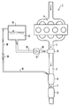
- FIG. 1 An embodiment of the invention is explained in more detail with reference to the drawing. It shows: The figure is a schematic representation of a device for denitrification of exhaust gas from an internal combustion engine, here a diesel engine, with a pressure relief line according to the invention.
- a device 1 for denitrification of the exhaust gases is connected.
- This comprises an ammonia generator 6, a DeNO x catalyst 8 and an oxidation catalyst 9.
- a reducing agent supply line 10 is connected to the ammonia generator 6 and connects the ammonia generator 6 to a storage container 14 via a reducing agent supply 12.
- a pressure relief line 18 is connected in the upper part of the storage container 14 and opens into the inlet of the DeNO x catalyst 8 via a pressure relief valve 20.
- the ammonia required for the catalytic conversion of the nitrogen oxides in the exhaust gas is reduced by means of the reducing agent supply 12 - in the present case an injection device - in the form of the aqueous urea solution 16 in those heated to the operating temperature by the exhaust gases (approx. 200 to 600 ° C.) Ammonia generator 6 injected. At these temperatures, the urea solution decomposes into ammonia and water on the hot surfaces of the ammonia generator 6. The ammonia formed in the ammonia generator 6 is then catalytically converted into nitrogen and water with the nitrogen oxides in the exhaust gas in the DeNO x catalyst 8.
- the decomposition vapor pressure of the urea solution rises as a result of this heating, as a result of which an excess pressure builds up in the storage container 14 due to the ammonia which forms. If this overpressure reaches a pressure of 1000 hPa in the exemplary embodiment, this opens into the Pressure relief line 18 built-in pressure relief valve 20. The excess ammonia then flows from the storage container 14 via the pressure relief line 18 into the inlet of the DeNO x catalytic converter 8 until the pressure at the pressure relief valve 20 has dropped below 1000 hPa again. The ammonia passed into the DeNO x catalyst 8 is bound to the catalytic material.
- the 50 l DeNO x catalyst 8 used in the exemplary embodiment is suitable for holding approximately 100 g ammonia, corresponding to a volume of approximately 130 standard liters of gaseous ammonia. The amount of ammonia absorbed in the DeNO x catalyst 8 is not released directly into the ambient air in this way.
- the ammonia taken up in the DeNO x catalyst 8 is then catalytically converted to nitrogen and water with the nitrogen oxides of the exhaust gas when the DeNO x catalyst 8 reaches the temperature above 250 ° C. which is sufficiently high for the catalytic conversion. Only when the ammonia taken up in the DeNO x catalytic converter 8 is completely used up again by the catalytic reaction, is ammonia in the form of the liquid urea solution 16 again metered into the ammonia generator 6 of the exhaust line 2.
- the storage container 14 for the aqueous urea solution 16 is installed in the interior of a motor vehicle and can be combined, for example, with the fuel container. It also makes sense to use the entire device for the denitrification of exhaust gas from the internal combustion engine, here the diesel engine 4, consisting of the reservoir 14, the reducing agent supply line 10, the reducing agent supply 12, the ammonia generator 6, the pressure relief line 18, the pressure relief valve 20 and the DeNO x - Catalyst 8, in to install a spatial unit between a manifold and a silencer in the motor vehicle.
- the diesel engine 4 consisting of the reservoir 14, the reducing agent supply line 10, the reducing agent supply 12, the ammonia generator 6, the pressure relief line 18, the pressure relief valve 20 and the DeNO x - Catalyst 8 in to install a spatial unit between a manifold and a silencer in the motor vehicle.
Landscapes
- Chemical & Material Sciences (AREA)
- Engineering & Computer Science (AREA)
- Chemical Kinetics & Catalysis (AREA)
- Health & Medical Sciences (AREA)
- Combustion & Propulsion (AREA)
- Biomedical Technology (AREA)
- Environmental & Geological Engineering (AREA)
- Analytical Chemistry (AREA)
- General Chemical & Material Sciences (AREA)
- Oil, Petroleum & Natural Gas (AREA)
- Toxicology (AREA)
- Mechanical Engineering (AREA)
- General Engineering & Computer Science (AREA)
- Exhaust Gas After Treatment (AREA)
Abstract
Description
Die Erfindung bezieht sich auf eine Einrichtung zur Entstickung von Abgas eines Verbrennungsmotors, insbesondere eines Dieselmotors, mit einer Abgasleitung, einem an der Abgasleitung angeschlossenen DeNOx-Katalysator, einem Vorratsbehälter für ein zumindest teilweise in Ammoniak umwandelbares Reduktionsmittel, einem dem DeNOx-Katalysator vorgeschalteten Ammoniakgenerator und einer Einrichtung zur Einbringung des Reduktionsmittels in das dem DeNOx-Katalysator zuströmenden Abgas.The invention relates to a device for the denitrification of exhaust gas from an internal combustion engine, in particular a diesel engine, with an exhaust pipe, a DeNO x catalyst connected to the exhaust pipe, a storage container for a reducing agent which can be converted at least partially into ammonia, a upstream of the DeNO x catalyst Ammonia generator and a device for introducing the reducing agent into the exhaust gas flowing into the DeNO x catalyst.
Zur Entstickung von Abgas eines Verbrennungsmotors, insbesondere eines Dieselmotors, sind Einrichtungen und Verfahren bekannt, die die Stickoxide analog zu dem in Kraftwerken bewährten Verfahren der selektiven katalytischen Reduktion (SCR) mit Ammoniak als Reduktionsmittel an sogenannten DeNOx- Katalysatoren zu Stickstoff reduzieren (DE-A-36 15 021, EP-A-0 277 765).For the denitrification of exhaust gas from an internal combustion engine, in particular a diesel engine, devices and methods are known which reduce the nitrogen oxides analogously to the method of selective catalytic reduction (SCR) proven in power plants with ammonia as a reducing agent on so-called DeNO x catalysts to nitrogen (DE- A-36 15 021, EP-A-0 277 765).
Ammoniak sollte jedoch aufgrund seiner Giftigkeit nicht im Fahrzeug mitgeführt werden, sondern sollte im Fahrzeug selbst aus einer ungiftigen Vorläufer-Substanz in kleinen, ausschließlich zum augenblicklichen Verbrauch im DeNOx-Katalysator bestimmte Mengen erzeugt werden. Die ungiftige Vorläufer-Substanz sollte hierbei unter Lagerbedingungen im Fahrzeug einen sehr geringen Dampfdruck entwickeln, so daß bei Unfällen oder bei Hitze (Stau) keine Gefahr einer Ammoniak-Geruchsbelästigung besteht. Eine geeignete Substanz ist Harnstoff, der in einem Vorratsbehälter in Form einer wäßrigen Lösung im Fahrzeug mitgeführt werden kann.However, due to its toxicity, ammonia should not be carried in the vehicle, but should be generated in the vehicle itself from a non-toxic precursor substance in small quantities, which are only intended for current consumption in the DeNO x catalytic converter. The non-toxic precursor substance should develop a very low vapor pressure under storage conditions in the vehicle, so that there is no risk of ammonia odors in accidents or in the event of heat (traffic jam). A suitable substance is urea, which is stored in a storage container Form of an aqueous solution can be carried in the vehicle.
Aus der wäßrigen Harnstofflösung entsteht durch Hydrolyse der zur SCR-Reaktion benötigte Ammoniak. Die Hydrolyse kann durch direktes Einspritzen einer wäßrigen Harnstofflösung in das heiße Abgas (DE-A-38 30 045) oder durch die Kontaktierung der wäßrigen Harnstofflösung mit einem Hydrolysekatalysator erfolgen. Als weitere ungiftige Vorläufer-Substanzen, die als Ammoniakspeicher dienen können, eignen sich auch diverse Ammoniumverbindungen.The ammonia required for the SCR reaction is formed from the aqueous urea solution by hydrolysis. The hydrolysis can be carried out by directly injecting an aqueous urea solution into the hot exhaust gas (DE-A-38 30 045) or by contacting the aqueous urea solution with a hydrolysis catalyst. Various other ammonium compounds are also suitable as further non-toxic precursors that can serve as ammonia stores.
Bei hohen Temperaturen, zum Beispiel bei Abstellen des Fahrzeugs in der Sonne oder in heißen Regionen, kann es zur Überhitzung des zumindest teilweise in Ammoniak umwandelbaren Reduktionsmittels kommen. Aufgrund des mit steigender Temperatur zunehmenden Zersetzungsdampfdrucks für zum Beispiel eine wäßrige Harnstofflösung muß das gebildete Ammoniak zur Druckentlastung des Vorratsbehälters entweichen können, ohne daß es zu einer Geruchsbelästigung durch Ammoniak kommt.At high temperatures, for example when the vehicle is parked in the sun or in hot regions, the reducing agent which is at least partially convertible to ammonia can overheat. Due to the increasing decomposition vapor pressure for an aqueous urea solution, for example, the ammonia formed must be able to escape to relieve the pressure on the storage container without causing an odor nuisance caused by ammonia.
Der Erfindung liegt daher die Aufgabe zugrunde, eine Einrichtung anzugeben, die für eine Druckentlastung im Vorratsbehälter sorgt, ohne daß es zu einer Geruchsbelästigung durch Ammoniak kommt.The invention is therefore based on the object of specifying a device which provides pressure relief in the storage container without causing an odor nuisance caused by ammonia.
Diese Aufgabe wird erfindungsgemäß dadurch gelöst, daß eine Druckentlastungsleitung an den Vorratsbehälter für ein zumindest teilweise in Ammoniak umwandelbares Reduktionsmittel angeschlossen ist, über die überschüssiges Reduktionsmittel dem DeNOx-Katalysator zuführbar ist. Auf diese Weise wird eine unzulässige Druckexkursion im Vorratsbehälter vermieden. Darüber hinaus wird die hohe Adsorptionskapazität üblicher DeNOx-Katalysatoren genutzt, um den überschüssigen Ammoniak zu binden und so zu vermeiden, daß das Ammoniak an die Umgebungsluft gelangt. Der im DeNOx-Katalysator aufgenommene Ammoniak wird - etwa nach der Wiederinbetriebnahme des Verbrennungsmotors - bei Erreichen der im Katalysator zur katalytischen Umsetzung notwendigen Temperatur mit den Stickoxiden katalytisch umgesetzt.This object is achieved in that a pressure relief line is connected to the reservoir for an at least partially convertible into ammonia reducing agent, via which excess reducing agent can be fed to the DeNO x catalyst. In this way, an impermissible pressure excursion in the reservoir is avoided. In addition, the high Adsorption capacity of conventional DeNO x catalysts used to bind the excess ammonia and thus to avoid that the ammonia gets into the ambient air. The ammonia taken up in the DeNO x catalytic converter is reacted catalytically with the nitrogen oxides, for example after the internal combustion engine has been put back into operation, when the temperature required for catalytic conversion in the catalytic converter is reached.
Es erweist sich als vorteilhaft, als zumindest teilweise in Ammoniak umwandelbares Reduktionsmittel eine wäßrige Harnstofflösung zu verwenden, die etwa 20 bis 60 %ig ist. Hierdurch kann einerseits mit dem Einspritzen kleiner Harnstoffmengen der zur katalytischen Umsetzung der Stickoxide benötigte Ammoniak bereitgestellt werden. Andererseits ist der Zersetzungsdampfdruck dieser wäßrigen Lösung niedrig genug, so daß nicht ständig überschüssiges Ammoniak dem DeNOx-Katalysator zugeführt werden muß.It proves to be advantageous to use an aqueous urea solution, which is approximately 20 to 60% strength, as a reducing agent which can be converted at least partially into ammonia. In this way, on the one hand, the ammonia required for the catalytic conversion of the nitrogen oxides can be provided by injecting small amounts of urea. On the other hand, the decomposition vapor pressure of this aqueous solution is low enough so that excess ammonia does not have to be continuously fed to the DeNO x catalyst.
In vorteilhafter Ausgestaltung der Erfindung enthält die Druckentlastungsleitung ein Überdruckventil. Hierdurch läßt sich die von dem DeNOx-Katalysator aufzunehmende Menge überschüssiges Ammoniak im Rahmen der Druckfestigkeit des Vorratsbehälters begrenzen.In an advantageous embodiment of the invention, the pressure relief line contains a pressure relief valve. This allows the amount of excess ammonia to be absorbed by the DeNO x catalyst within the pressure resistance of the storage container.
Ein Ausführungsbeispiel der Erfindung wird anhand der Zeichnung näher erläutert. Dabei zeigt:
Die Figur eine schematische Darstellung einer Einrichtung zur Entstickung von Abgas eines Verbrennungsmotors, hier eines Dieselmotors, mit einer erfindungsgemäßen Druckentlastungsleitung.An embodiment of the invention is explained in more detail with reference to the drawing. It shows:
The figure is a schematic representation of a device for denitrification of exhaust gas from an internal combustion engine, here a diesel engine, with a pressure relief line according to the invention.
An der in der Figur schematisch dargestellten Abgasleitung 2 eines Dieselmotors 4 ist eine Einrichtung 1 zur Entstickung der Abgase angeschlossen. Diese umfaßt einen Ammoniakgenerator 6, einen DeNOx-Katalysator 8 und einen Oxidationskatalysator 9. An den Ammoniakgenerator 6 ist eine Reduktionsmittelzuführungsleitung 10 angeschlossen, die den Ammoniakgenerator 6 über eine Reduktionsmittelzuführung 12 mit einem Vorratsbehälter 14 verbindet. Im Vorratsbehälter 14 befindet sich eine wäßrige Harnstofflösung 16. Im oberen Teil des Vorratsbehälters 14 ist eine Druckentlastungsleitung 18 angeschlossen, die über ein Überdruckventil 20 in den Eingang des DeNOx-Katalysators 8 mündet.On the exhaust pipe shown schematically in the figure 2 of a diesel engine 4, a device 1 for denitrification of the exhaust gases is connected. This comprises an
Beim Betrieb des Dieselmotors 4 wird das zur katalytischen Umsetzung der Stickoxide im Abgas erforderliche Ammoniak mittels der Reduktionsmittelzuführung 12 - im vorliegenden Fall eine Einspritzvorrichtung - in Form der wäßrigen Harnstofflöstung 16 in den durch die Abgase auf Betriebstemperatur aufgeheizten (ca. 200 bis 600 °C) Ammoniakgenerator 6 eingedüst. Bei diesen Temperaturen zersetzt sich die Harnstofflösung an den heißen Oberflächen des Ammoniakgenerators 6 in Ammoniak und Wasser. Das im Ammoniakgenerator 6 gebildete Ammoniak wird anschließend mit den im Abgas befindlichen Stickoxiden in dem DeNOx-Katalysator 8 zu Stickstoff und Wasser katalytisch umgesetzt.During operation of the diesel engine 4, the ammonia required for the catalytic conversion of the nitrogen oxides in the exhaust gas is reduced by means of the reducing agent supply 12 - in the present case an injection device - in the form of the
Kommt es zu einer Erwärmung der im Ausführungsbeispiel 20 bis 60 %igen wäßrigen Harnstofflösung 16 im Vorratsbehälter 14, steigt durch diese Erwärmung der Zersetzungsdampfdruck der Harnstofflösung, wodurch sich ein Überdruck im Vorratsbehälter 14 durch das sich bildende Ammoniak aufbaut. Erreicht dieser Überdruck im Ausführungsbeispiel einen Druck von 1000 hPa, öffnet sich das in die Druckentlastungsleitung 18 eingebaute Überdruckventil 20. Das überschüssige Ammoniak strömt dann aus dem Vorratsbehälter 14 über die Druckentlastungsleitung 18 in den Eingang des DeNOx-Katalysators 8, bis der Druck am Überdruckventil 20 wieder unter 1000 hPa abgesunken ist. Das in den DeNOx-Katalysator 8 geleitete Ammoniak wird an dem katalytischen Material gebunden. Der im Ausführungsbeispiel verwendete 50 l DeNOx-Katalysator 8 eignet sich zur Aufnahme von ca. 100 g Ammoniak, entsprechend einem Volumen von etwa 130 Normlitern gasförmigen Ammoniaks. Die im DeNOx-Katalysator 8 aufgenommene Ammoniakmenge wird auf diese Weise nicht direkt an die Umgebungsluft abgegeben.If the 20 to 60%
Das im DeNOx-Katalysator 8 aufgenommene Ammoniak wird anschließend mit den Stickoxiden des Abgases katalytisch zu Stickstoff und Wasser umgesetzt, wenn der DeNOx-Katalysator 8 die zur katalytischen Umsetzung hinreichend hohe Temperatur oberhalb 250 °C erreicht. Erst wenn der im DeNOx-Katalysator 8 aufgenommene Ammoniak wieder durch die katalytische Reaktion vollständig verbraucht ist, wird wieder gezielt Ammoniak in Form der flüssigen Harnstofflösung 16 in den Ammoniakgenerator 6 der Abgasleitung 2 zudosiert.The ammonia taken up in the DeNO x catalyst 8 is then catalytically converted to nitrogen and water with the nitrogen oxides of the exhaust gas when the DeNO x catalyst 8 reaches the temperature above 250 ° C. which is sufficiently high for the catalytic conversion. Only when the ammonia taken up in the DeNO x catalytic converter 8 is completely used up again by the catalytic reaction, is ammonia in the form of the
Zum Schutz vor direkter Sonnenbestrahlung ist der Vorratsbehälter 14 für die wäßrige Harnstofflösung 16 im Inneren eines Kraftfahrzeuges eingebaut und kann beispielsweise mit dem Kraftstoffbehälter kombiniert werden. Es ist außerdem sinnvoll, die gesamte Einrichtung zur Entstickung von Abgas des Verbrennungsmotors, hier des Dieselmotors 4, bestehend aus dem Vorratsbehälter 14, der Reduktionsmittelzuführungsleitung 10, der Reduktionsmittelzuführung 12, dem Ammoniakgenerator 6, der Druckentlastungsleitung 18, dem Überdruckventil 20 und dem DeNOx-Katalysator 8, in einer räumlichen Einheit zwischen einem Krümmer und einem Schalldämpfer im Kraftfahrzeug zu installieren.To protect against direct sunlight, the
Claims (7)
- A device for the removal of nitrogen from the exhaust gases of a combustion engine, particularly a diesel engine, with an exhaust pipe (2), a DeNOx catalyst (8) attached to the exhaust pipe, a storage vessel (14) for a reducing agent (16) that can be converted at least partially to ammonia, an ammonia generator (6) upstream of the DeNOx catalyst (8), and a device (12) for introducing the reducing agent into the exhaust gas flowing into the DeNOx catalyst (8), characterised in that attached to the storage vessel (14) is a pressure relief line (18) through which excess reducing agent can be fed to the DeNOx catalyst (8).
- A device according to claim 1, characterised in that the reducing agent that can be converted at least partially to ammonia is an aqueous urea solution (16).
- A device according to claim 2, characterised by a 20 to 60% aqueous urea solution (16).
- A device according to claim 1, characterised in that the reducing agent that can be converted to ammonia is aqueous ammonia.
- A device according to one of claims 1 to 4, characterised in that the pressure relief line (18) contains a pressure relief valve (20).
- A device according to one of claims 1 to 5, characterised in that the pressure relief line (18) is attached to the inlet of the DeNOx catalyst (8).
- A device according to one of claims 1 to 6, characterised in that an oxidation catalyst (9) for excess ammonia is provided downstream of the DeNOx catalyst (8).
Priority Applications (4)
| Application Number | Priority Date | Filing Date | Title |
|---|---|---|---|
| AT92107824T ATE122261T1 (en) | 1992-05-08 | 1992-05-08 | DEVICE FOR DENOTIGOROUSIZING EXHAUST GAS FROM AN INCOMMODATION ENGINE. |
| DE59202165T DE59202165D1 (en) | 1992-05-08 | 1992-05-08 | Device for the denitrification of exhaust gas from an internal combustion engine. |
| EP92107824A EP0577853B1 (en) | 1992-05-08 | 1992-05-08 | Denitration device for exhaust gases of internal combustion motors |
| ES92107824T ES2071372T3 (en) | 1992-05-08 | 1992-05-08 | INSTALLATION FOR THE DENITRATION OF THE EXHAUST GAS OF AN INTERNAL COMBUSTION ENGINE. |
Applications Claiming Priority (1)
| Application Number | Priority Date | Filing Date | Title |
|---|---|---|---|
| EP92107824A EP0577853B1 (en) | 1992-05-08 | 1992-05-08 | Denitration device for exhaust gases of internal combustion motors |
Publications (2)
| Publication Number | Publication Date |
|---|---|
| EP0577853A1 EP0577853A1 (en) | 1994-01-12 |
| EP0577853B1 true EP0577853B1 (en) | 1995-05-10 |
Family
ID=8209602
Family Applications (1)
| Application Number | Title | Priority Date | Filing Date |
|---|---|---|---|
| EP92107824A Expired - Lifetime EP0577853B1 (en) | 1992-05-08 | 1992-05-08 | Denitration device for exhaust gases of internal combustion motors |
Country Status (4)
| Country | Link |
|---|---|
| EP (1) | EP0577853B1 (en) |
| AT (1) | ATE122261T1 (en) |
| DE (1) | DE59202165D1 (en) |
| ES (1) | ES2071372T3 (en) |
Cited By (5)
| Publication number | Priority date | Publication date | Assignee | Title |
|---|---|---|---|---|
| GB2308820B (en) * | 1994-11-18 | 1998-08-26 | Komatsu Mfg Co Ltd | Exhaust denitration for diesel engines |
| WO1999049958A1 (en) | 1998-03-27 | 1999-10-07 | Siemens Aktiengesellschaft | Internal combustion engine exhaust system and method for reducing contaminants in exhaust gases |
| WO1999056858A2 (en) * | 1998-04-30 | 1999-11-11 | Siemens Aktiengesellschaft | Method and device for catalytic reduction of nitrogen oxide |
| DE19929935A1 (en) * | 1999-06-29 | 2000-07-27 | Siemens Ag | Device for removing nitrogen from I.C. engine exhaust gas has an additional catalyst connected to a first catalyst so that it acts simultaneously as reductant generator |
| DE19956493C1 (en) * | 1999-11-24 | 2001-01-04 | Siemens Ag | Device for removing nitrogen oxides from I.C. engine exhaust gas comprises a flow-through measuring device that determines the amount of excess reductant arranged in the pressure relieving line |
Families Citing this family (14)
| Publication number | Priority date | Publication date | Assignee | Title |
|---|---|---|---|---|
| DE4432577A1 (en) * | 1994-09-13 | 1996-03-14 | Siemens Ag | Assembly for introduction of liq. into selective catalytic redn. assembly |
| DE4432576A1 (en) * | 1994-09-13 | 1996-03-14 | Siemens Ag | Electrically heated assembly delivers fluid to automotive exhaust gases |
| DE19827678B4 (en) | 1998-06-22 | 2010-05-20 | Hjs Fahrzeugtechnik Gmbh & Co | Emission control system for removing exhaust gases from combustion units |
| EP2426329B1 (en) * | 2003-09-19 | 2013-05-01 | Nissan Diesel Motor Co., Ltd. | Exhaust gas purification device of engine |
| JP4681284B2 (en) * | 2004-11-18 | 2011-05-11 | 日野自動車株式会社 | Exhaust purification device |
| DE202005000896U1 (en) * | 2004-11-30 | 2006-04-06 | Hengst Gmbh & Co.Kg | Ion exchanger, especially for purifying urea solutions for use in automobile exhaust emission control systems, comprises expansion chamber whose volume decreases with increase in fluid pressure |
| DE202005000897U1 (en) * | 2004-11-30 | 2006-04-06 | Hengst Gmbh & Co.Kg | Ion exchanger, especially for purifying urea solutions for use in automobile exhaust emission control systems, comprises expansion chamber whose volume decreases with increase in fluid pressure |
| US20070277505A1 (en) * | 2006-05-30 | 2007-12-06 | Ford Global Technologies, Llc | Venting of on-board vehicle emissions treatment system |
| US20070289288A1 (en) * | 2006-06-19 | 2007-12-20 | Ford Global Technologies, Llc | Venting of on-board vehicle emissions treatment system with pressure assist |
| FR2903727B1 (en) * | 2006-07-12 | 2008-09-05 | Inergy Automotive Systems Res | STORAGE SYSTEM FOR AMMONIA PRECURSOR |
| FR2907026B1 (en) * | 2006-10-13 | 2009-05-15 | Peugeot Citroen Automobiles Sa | SYSTEM FOR TREATING NITROGEN OXIDES WITH AN AMMONIA TRAPPING SYSTEM |
| FR2907027B1 (en) * | 2006-10-13 | 2009-05-15 | Peugeot Citroen Automobiles Sa | SYSTEM FOR TREATING NITROGEN OXIDES WITH LIMITATION OF AMMONIA RELEASES |
| DE102010020581B4 (en) | 2010-05-14 | 2024-01-25 | Volkswagen Ag | Reducing agent storage system for an SCR exhaust system |
| FR3010135B1 (en) * | 2013-09-05 | 2018-03-02 | Peugeot Citroen Automobiles Sa | SYSTEM FOR SUPPLYING REDUCING AGENT OF AN EXHAUST LINE |
Family Cites Families (1)
| Publication number | Priority date | Publication date | Assignee | Title |
|---|---|---|---|---|
| DE3830045C2 (en) * | 1988-09-03 | 1993-09-30 | Bayer Ag | Process for the reduction of nitrogen oxides contained in exhaust gases by means of a zeolite-containing catalyst |
-
1992
- 1992-05-08 EP EP92107824A patent/EP0577853B1/en not_active Expired - Lifetime
- 1992-05-08 DE DE59202165T patent/DE59202165D1/en not_active Expired - Lifetime
- 1992-05-08 AT AT92107824T patent/ATE122261T1/en active
- 1992-05-08 ES ES92107824T patent/ES2071372T3/en not_active Expired - Lifetime
Cited By (8)
| Publication number | Priority date | Publication date | Assignee | Title |
|---|---|---|---|---|
| GB2308820B (en) * | 1994-11-18 | 1998-08-26 | Komatsu Mfg Co Ltd | Exhaust denitration for diesel engines |
| WO1999049958A1 (en) | 1998-03-27 | 1999-10-07 | Siemens Aktiengesellschaft | Internal combustion engine exhaust system and method for reducing contaminants in exhaust gases |
| US6357227B1 (en) | 1998-03-27 | 2002-03-19 | Siemens Aktiengesellschaft | System and method for reducing pollutants in the exhaust gas of an internal combustion engine |
| WO1999056858A2 (en) * | 1998-04-30 | 1999-11-11 | Siemens Aktiengesellschaft | Method and device for catalytic reduction of nitrogen oxide |
| DE19929935A1 (en) * | 1999-06-29 | 2000-07-27 | Siemens Ag | Device for removing nitrogen from I.C. engine exhaust gas has an additional catalyst connected to a first catalyst so that it acts simultaneously as reductant generator |
| DE19956493C1 (en) * | 1999-11-24 | 2001-01-04 | Siemens Ag | Device for removing nitrogen oxides from I.C. engine exhaust gas comprises a flow-through measuring device that determines the amount of excess reductant arranged in the pressure relieving line |
| WO2001038703A1 (en) | 1999-11-24 | 2001-05-31 | Siemens Aktiengesellschaft | Device and method for the nitrogen oxide control of waste gas in an internal combustion engine |
| US6637196B1 (en) | 1999-11-24 | 2003-10-28 | Siemens Aktiengesellschaft | Device and method for denoxing exhaust gas from an internal combustion engine |
Also Published As
| Publication number | Publication date |
|---|---|
| DE59202165D1 (en) | 1995-06-14 |
| ES2071372T3 (en) | 1995-06-16 |
| EP0577853A1 (en) | 1994-01-12 |
| ATE122261T1 (en) | 1995-05-15 |
Similar Documents
| Publication | Publication Date | Title |
|---|---|---|
| EP0577853B1 (en) | Denitration device for exhaust gases of internal combustion motors | |
| DE19728343C5 (en) | Process and apparatus for selective catalytic NOx reduction | |
| EP1395351B1 (en) | Exhaust gas purification unit with reducing agent supply | |
| DE60313236T2 (en) | NOx reduction system for diesel engines using a hydrogen selective catalytic reduction | |
| DE19720209C1 (en) | Reducing nitrogen oxide(s) in I.C. engine exhaust gas | |
| EP0775013B1 (en) | Method for the catalytic reaction of oxides of nitrogen in the exhaust from an internal-combustion engine | |
| DE102014103678B4 (en) | COMPACT EXHAUST TREATMENT SYSTEM FOR A DIESEL ENGINE | |
| EP1338562B1 (en) | Process and apparatus for producing ammonia | |
| DE102007060623B4 (en) | Denitrification of diesel engine exhaust gases using a tempered pre-catalyst for on-demand NO2 provision | |
| DE10349126A1 (en) | exhaust aftertreatment systems | |
| WO1999056858A2 (en) | Method and device for catalytic reduction of nitrogen oxide | |
| DE10139142A1 (en) | Exhaust gas treatment unit and measuring device for determining a concentration of a urea-water solution | |
| DE10251472A1 (en) | Reduction of automotive nitrous oxide emissions during cold start comprises supplementary injection of ammonia from holding reservoir | |
| DE112006003231T5 (en) | Multi-stage system for selective catalytic reduction | |
| DE102008062669A1 (en) | Exhaust system with improved NOx emission control | |
| EP1066105A1 (en) | Internal combustion engine exhaust system and method for reducing contaminants in exhaust gases | |
| WO1997007876A2 (en) | Method and device for decomposing oxides of nitrogen in the exhaust gases from an internal-combustion engine | |
| DE102014019427A1 (en) | Process for cleaning diesel engine exhaust gases | |
| WO2001083087A1 (en) | Method and device for exhaust gas purification | |
| DE29708591U1 (en) | Device for feeding ammonia into the exhaust gas stream of an internal combustion engine | |
| DE4214183A1 (en) | Exhaust gas treatment for IC (diesel) engine - has reducing catalyst for nitrogen oxide with ammonia addition, and downstream oxidative catalyst | |
| DE102007027444A1 (en) | Pollutant treatment system aerating method for use in vehicle, involves directly connecting storage tank with exhaust system that is connected upstream of ammonia storage unit for conveying steam from storage tank | |
| EP2313181B1 (en) | Method for the controlled feeding of a reducing agent | |
| DE102017106757A1 (en) | System and method for exhaust treatment of combustion devices | |
| DE1244477B (en) | Catalytic converter muffler |
Legal Events
| Date | Code | Title | Description |
|---|---|---|---|
| PUAI | Public reference made under article 153(3) epc to a published international application that has entered the european phase |
Free format text: ORIGINAL CODE: 0009012 |
|
| AK | Designated contracting states |
Kind code of ref document: A1 Designated state(s): AT BE CH DE DK ES FR GB GR IT LI LU MC NL PT SE |
|
| RBV | Designated contracting states (corrected) |
Designated state(s): AT CH DE ES FR GB IT LI NL SE |
|
| 17P | Request for examination filed |
Effective date: 19940207 |
|
| 17Q | First examination report despatched |
Effective date: 19941021 |
|
| GRAA | (expected) grant |
Free format text: ORIGINAL CODE: 0009210 |
|
| AK | Designated contracting states |
Kind code of ref document: B1 Designated state(s): AT CH DE ES FR GB IT LI NL SE |
|
| REF | Corresponds to: |
Ref document number: 122261 Country of ref document: AT Date of ref document: 19950515 Kind code of ref document: T |
|
| REF | Corresponds to: |
Ref document number: 59202165 Country of ref document: DE Date of ref document: 19950614 |
|
| REG | Reference to a national code |
Ref country code: ES Ref legal event code: FG2A Ref document number: 2071372 Country of ref document: ES Kind code of ref document: T3 |
|
| GBT | Gb: translation of ep patent filed (gb section 77(6)(a)/1977) |
Effective date: 19950622 |
|
| ITF | It: translation for a ep patent filed | ||
| ET | Fr: translation filed | ||
| PLBE | No opposition filed within time limit |
Free format text: ORIGINAL CODE: 0009261 |
|
| STAA | Information on the status of an ep patent application or granted ep patent |
Free format text: STATUS: NO OPPOSITION FILED WITHIN TIME LIMIT |
|
| 26N | No opposition filed | ||
| REG | Reference to a national code |
Ref country code: GB Ref legal event code: IF02 |
|
| PGFP | Annual fee paid to national office [announced via postgrant information from national office to epo] |
Ref country code: ES Payment date: 20030522 Year of fee payment: 12 |
|
| PGFP | Annual fee paid to national office [announced via postgrant information from national office to epo] |
Ref country code: CH Payment date: 20030523 Year of fee payment: 12 |
|
| PG25 | Lapsed in a contracting state [announced via postgrant information from national office to epo] |
Ref country code: ES Free format text: LAPSE BECAUSE OF NON-PAYMENT OF DUE FEES Effective date: 20040510 |
|
| PG25 | Lapsed in a contracting state [announced via postgrant information from national office to epo] |
Ref country code: LI Free format text: LAPSE BECAUSE OF NON-PAYMENT OF DUE FEES Effective date: 20040531 Ref country code: CH Free format text: LAPSE BECAUSE OF NON-PAYMENT OF DUE FEES Effective date: 20040531 |
|
| REG | Reference to a national code |
Ref country code: CH Ref legal event code: PL |
|
| REG | Reference to a national code |
Ref country code: ES Ref legal event code: FD2A Effective date: 20040510 |
|
| REG | Reference to a national code |
Ref country code: FR Ref legal event code: TP |
|
| REG | Reference to a national code |
Ref country code: GB Ref legal event code: 732E Free format text: REGISTERED BETWEEN 20090528 AND 20090603 |
|
| REG | Reference to a national code |
Ref country code: NL Ref legal event code: SD Effective date: 20100615 |
|
| REG | Reference to a national code |
Ref country code: NL Ref legal event code: TD Effective date: 20110420 |
|
| PGFP | Annual fee paid to national office [announced via postgrant information from national office to epo] |
Ref country code: SE Payment date: 20110513 Year of fee payment: 20 Ref country code: FR Payment date: 20110607 Year of fee payment: 20 |
|
| PGFP | Annual fee paid to national office [announced via postgrant information from national office to epo] |
Ref country code: GB Payment date: 20110520 Year of fee payment: 20 Ref country code: AT Payment date: 20110512 Year of fee payment: 20 Ref country code: NL Payment date: 20110520 Year of fee payment: 20 |
|
| PGFP | Annual fee paid to national office [announced via postgrant information from national office to epo] |
Ref country code: DE Payment date: 20110520 Year of fee payment: 20 Ref country code: IT Payment date: 20110530 Year of fee payment: 20 |
|
| REG | Reference to a national code |
Ref country code: DE Ref legal event code: R071 Ref document number: 59202165 Country of ref document: DE |
|
| REG | Reference to a national code |
Ref country code: AT Ref legal event code: HC Ref document number: 122261 Country of ref document: AT Kind code of ref document: T Owner name: JOHNSON MATTHEY CATALYSTS (GERMANY) GMBH, DE Effective date: 20120411 |
|
| REG | Reference to a national code |
Ref country code: NL Ref legal event code: V4 Effective date: 20120508 |
|
| REG | Reference to a national code |
Ref country code: GB Ref legal event code: PE20 Expiry date: 20120507 |
|
| REG | Reference to a national code |
Ref country code: SE Ref legal event code: EUG |
|
| REG | Reference to a national code |
Ref country code: FR Ref legal event code: CD Owner name: JOHNSON MATTHEY CATALYSTS GERMANY GMBH, DE Effective date: 20120615 |
|
| PG25 | Lapsed in a contracting state [announced via postgrant information from national office to epo] |
Ref country code: GB Free format text: LAPSE BECAUSE OF EXPIRATION OF PROTECTION Effective date: 20120507 |
|
| REG | Reference to a national code |
Ref country code: AT Ref legal event code: MK07 Ref document number: 122261 Country of ref document: AT Kind code of ref document: T Effective date: 20120508 |
|
| REG | Reference to a national code |
Ref country code: DE Ref legal event code: R082 Ref document number: 59202165 Country of ref document: DE Representative=s name: FDST PATENTANWAELTE FREIER DOERR STAMMLER TSCH, DE |
|
| REG | Reference to a national code |
Ref country code: DE Ref legal event code: R082 Ref document number: 59202165 Country of ref document: DE Representative=s name: FDST PATENTANWAELTE FREIER DOERR STAMMLER TSCH, DE Effective date: 20121004 Ref country code: DE Ref legal event code: R081 Ref document number: 59202165 Country of ref document: DE Owner name: JOHNSON MATTHEY CATALYSTS (GERMANY) GMBH, DE Free format text: FORMER OWNER: ARGILLON GMBH, 96257 REDWITZ, DE Effective date: 20121004 |
|
| PG25 | Lapsed in a contracting state [announced via postgrant information from national office to epo] |
Ref country code: DE Free format text: LAPSE BECAUSE OF EXPIRATION OF PROTECTION Effective date: 20120508 |