EP0577706B1 - A method for drying a subterranean cavern - Google Patents
A method for drying a subterranean cavern Download PDFInfo
- Publication number
- EP0577706B1 EP0577706B1 EP92908584A EP92908584A EP0577706B1 EP 0577706 B1 EP0577706 B1 EP 0577706B1 EP 92908584 A EP92908584 A EP 92908584A EP 92908584 A EP92908584 A EP 92908584A EP 0577706 B1 EP0577706 B1 EP 0577706B1
- Authority
- EP
- European Patent Office
- Prior art keywords
- gas
- cavern
- conduits
- water
- conduit
- Prior art date
- Legal status (The legal status is an assumption and is not a legal conclusion. Google has not performed a legal analysis and makes no representation as to the accuracy of the status listed.)
- Expired - Lifetime
Links
Images




Classifications
-
- B—PERFORMING OPERATIONS; TRANSPORTING
- B65—CONVEYING; PACKING; STORING; HANDLING THIN OR FILAMENTARY MATERIAL
- B65G—TRANSPORT OR STORAGE DEVICES, e.g. CONVEYORS FOR LOADING OR TIPPING, SHOP CONVEYOR SYSTEMS OR PNEUMATIC TUBE CONVEYORS
- B65G5/00—Storing fluids in natural or artificial cavities or chambers in the earth
-
- E—FIXED CONSTRUCTIONS
- E21—EARTH OR ROCK DRILLING; MINING
- E21B—EARTH OR ROCK DRILLING; OBTAINING OIL, GAS, WATER, SOLUBLE OR MELTABLE MATERIALS OR A SLURRY OF MINERALS FROM WELLS
- E21B43/00—Methods or apparatus for obtaining oil, gas, water, soluble or meltable materials or a slurry of minerals from wells
- E21B43/12—Methods or apparatus for controlling the flow of the obtained fluid to or in wells
- E21B43/121—Lifting well fluids
Definitions
- the present invention relates to a method for reducing the water content of a natural or artificial subterranean cavern, in particular an artificially created subterranean cavern which is to be used for the storage of a fluid (i.e. a liquid or mixture of liquids, or a gas or mixture of gases), particularly "natural gas” [i.e. a methane-rich, readily combustible mixture of gases which is generally believed to derive from the slow natural breakdown or decomposition of deposits of organic matter of plant or animal origin], and for which fluid it is desirable that the water content during storage should not exceed a certain limit.
- a fluid i.e. a liquid or mixture of liquids, or a gas or mixture of gases
- natural gas i.e. a methane-rich, readily combustible mixture of gases which is generally believed to derive from the slow natural breakdown or decomposition of deposits of organic matter of plant or animal origin
- a (normally essentially vertical) shaft or bore is drilled from the Earth's surface downwards into the underground salt deposit in question to some desired depth.
- This casing is typically constructed of coupled sections of steel pipe having an external diameter which is slightly less than the internal diameter of the shaft itself; the space between the casing and the inside wall of the shaft is normally filled with cement.
- This lining or casing is normally introduced at the stage where the shaft has been drilled down to a depth which is somewhat below the uppermost part of the deposit in question, the bottom of the established casing then being at about this point. After establishment of the casing, drilling is continued until the final desired depth of the shaft is reached.
- Two conduits e.g. pipe conduits made up of appropriately coupled lengths of steel tubing, suitably such that one extends essentially to the bottom of the shaft while the other is slightly shorter, are then normally established in the shaft.
- One of the conduits (in the following denoted the “water conduit”) is used to pump water (normally water at ambient temperature, since the solubility of sodium chloride as a function of water temperature varies only slightly) down to the salt formation, and the other (in the following referred to as the “brine conduit”) is used to transport salt solution (brine) up to the Earth's surface.
- the water conduit and the brine conduit are very suitably substantially concentric conduits, in which case the conduit having the smaller diameter (and extending within the conduit of larger diameter) is the longer of the two.
- the conduits may then be exploited in a manner such that the water conduit and the brine conduit initially are the longer (i.e. smaller diameter) and the shorter (i.e. larger diameter) conduit, respectively, or vice versa.
- the motivation of the two conduits may subsequently be reversed as the process of salt dissolution progresses.
- salt deposits of relatively great vertical thickness such as “salt domes”
- Such variations can be achieved by suitably varying the role, the relative placement and the relative movement of the conduits.
- the first task is to remove the brine remaining in the cavern.
- a fluid e.g. natural gas
- brine-withdrawal conduit which is of smaller diameter than the production conduit and which extends within the production conduit (preferably substantially concentrically); the brine-withdrawal conduit extends substantially down to the bottom of the cavern. It is, of course, not essential that the brine-withdrawal conduit extends within the production conduit; however, the alternative use of two essentially parallel conduits will require that a seal must be established around both conduits rather than just one, and this may, in practice, be considerably more difficult to achieve.
- Non-limiting examples of sets of dimensions (in inches) of essentially circularly cylindrical (and substantially concentric) casings, production conduits and brine-withdrawal conduits which are fairly commonly employed in connection with caverns for the storage of natural gas are 13 3/8", 9 5/8" and 4 1/2", respectively, and 9 5/8", 7 5/8" and 4", respectively (the given dimensions being outside diameters)
- the cavern may still retain some (in principle removable) water [e.g.
- aqueous phase in and/or on the cavern walls and/or in small crevices or recesses in the cavern; some aqueous phase will normally also remain in the lowest-lying regions of the cavern, e.g. in a so-called "sump" present at the bottom of the cavern (the sump may, for example, be a depression at the bottom of the cavern corresponding to what was originally the bottom of the drilled shaft), and for some reason (e.g. the presence of lumps of insoluble rock or other debris which has fallen into a "sump") be inaccessible for removal, or at least partial removal, in the manner described above.
- sump sealing An extensive technology, generally referred to as "sump sealing", has developed in connection with the sealing off of reservoirs of aqueous phase (typically aqueous phase lying inaccessible in a sump of the above-mentioned type) present at the bottom of subterranean caverns, and there are numerous patent documents relating to this field.
- the general principle underlying the majority of proposed approaches to sump sealing is the introduction into the cavern of material(s) which either directly or indirectly lead(s) to the formation of a substantially water-insoluble and water/water vapour-impermeable barrier (generally referred to as a "sump seal”) covering the surface of the aqueous phase in question.
- Such barriers may, e.g., be provided by a layer of a liquid or semi-liquid hydrocarbon fraction of low volatility, or of a synthetic polymer formed by in situ polymerization of one or more appropriate, preferably liquid, monomers.
- Sump seals which remain liquid, or can at least flow have the advantage that they are "self-healing", i.e. the flowability of such a sump-sealing material will result in the rapid disappearance of any breakage in the surface of the sump seal caused, e.g., by falls of rock, debris or the like within the cavern.
- the material(s) to be used to sump-seal a cavern may suitably be introduced into a cavern of the type described here via the now disused brine-withdrawal conduit. After a sump seal has been established, as well as in the case of caverns for which it has not been regarded necessary to establish a sump-seal, it has hitherto been normal practice to remove the brine-withdrawal conduit completely.
- Natural gas is, as previously mentioned, rich in methane, and often contains appreciable amounts of higher alkanes, notably ethane (C 2 H 6 ) and propane (C 3 H 8 ).
- gas molecules are thus not chemically bonded (in the normal sense of the word) to surrounding water molecules, and the formation of such gas hydrates is, in general, readily reversible.
- gas hydrates often exhibit a crystal structure having a cubic unit cell containing 46 H 2 O molecules, and in the case of methane (and correspondingly for the examples of inert gases mentioned above) the ideal clathrate composition 8CH 4 .46H 2 O has been established, i.e. the ideal empirical formula is approximately CH 4 .6H 2 O.
- methane hydrate species having a considerably smaller methane:water ratio such as a species with the approximate empirical formula CH 4 .19H 2 O, have been identified.
- This gas hydrate which resembles snow in appearance and consistency, can rather quickly lead to complete or partial blockage or clogging of, e.g., reduction valves, filters and/or other above-ground installations forming a part of the gas-withdrawal and gas-process system; there may also, e.g. under extreme temperature and/or gas-withdrawal conditions, eventually be a risk of partial or complete blockage of the upper regions of the gas-withdrawal conduit.
- DE-A-3422240 a method for reducing the water-vapour content in natural gas stored in subterranean caverns is described.
- the temperature of the stored gas is reduced so as to reduce the risk of formation of gas hydrates in the above-ground installations.
- the temperature is reduced either by introduction of liquid and/or cooled gas (direct cooling) or by adapting a cooling system to the cavern (indirect cooling). In this way a part of the water-vapour is condensed in the cavity and cooled natural gas having a lower water-vapour content can be withdrawn from the cavity but only as long as the temperature reduction is maintained.
- the method of the invention is not limited to applications relating to the underground storage of gas, but is believed to be useful for reducing the water content of numerous types of caverns and for a wide variety of purposes.
- One aspect of the present invention thus provides a method for reducing the water content of a natural or artificial subterranean cavern
- subterranean cavern in the context of the invention is meant any cavern, cavity, cave or hollowed-out space situated below or within the boundaries of the earth's surface.
- a cavern may be one which occurs naturally in, or has been artificially created in, geological strata or formations comprising materials such as, for example, igneous or metamorphic rocks (e.g. basalt or granite) or sedimentary rocks (e.g. chalk, limestone or salt).
- igneous or metamorphic rocks e.g. basalt or granite
- sedimentary rocks e.g. chalk, limestone or salt.
- included within the definition of a subterranean cavern are, e.g., natural or artificial caverns, cavities, caves or hollowed-out spaces in mountains, cliffs, hills and the like.
- the cavern(s) in question may be of natural or artificial origin, and in the latter case the cavern(s) may be have been formed, for example, by drilling, by excavation, by blasting (i.e. by use of explosives), by dissolution [as, e.g., in the case of caverns formed as a result of solution-mining of crude sodium chloride ("rock salt” and the like) or some other water-soluble salt(s) (possible examples being potassium or sodium nitrate)], by flushing [e.g.
- flushing-out by means of, e.g., a stream or jet of water or other fluid
- inorganic or organic debris or other loose material from a cavity wholly or partly filled with such debris or material, or eroding away relatively soft material from a deposit or formation consisting of such material by means of, e.g, a high-pressure jet of water or other fluid] or by any other appropriate method.
- the introduction of the relatively dry gas into the cavern and the withdrawal of gas having a higher water vapour content from the cavern may take place substantially simultaneously and continuously, or substantially simultaneously and discontinuously.
- the introduction of the relatively dry gas into the cavern and the withdrawal of gas having a higher water vapour content from the cavern may take place in an alternating, cyclic manner, i.e. such that relatively dry gas is first introduced into the cavern for some appropriate length of time, after which (i.e.
- gas is withdrawn from the cavern for a further appropriate length of time (it is, of course, equally possible to start the process with gas-withdrawal as the very first step, and in this case it may, for example, further be advantageous to withdraw an atypically large amount of gas from the cavern in the very first gas-withdrawal step so as to achieve as large as initial reduction in the total water content within the cavern as possible); this alternating sequence of introduction of relatively dry gas and withdrawal of "moist" gas is repeated an appropriately large number of times.
- the cavern in question is a cavern to be used for the storage of natural gas and the purpose of performing the process is primarily to reduce the water-vapour content of gas to be withdrawn from the cavern, thereby reducing or eliminating gas hydrate formation during gas withdrawal
- the method of the invention may be employed to reduce the water content of subterranean caverns intended for a wide variety of different uses, and it will be further apparent that the method is particularly suited to caverns to which access by human beings is impossible or impracticable, and/or for which the introduction of and/or use of conventional drying means (e.g. hot-air "cannons" and the like) is impossible or impracticable.
- conventional drying means e.g. hot-air "cannons" and the like
- the cavern in question is a cavern for the storage of a fluid, particularly a cavern for the storage of natural gas.
- Natural gas (as well as LPG) is, of course, highly inflammable and forms explosive mixtures with air or oxygen, and it is thus clear that an oxygen-containing gas, such as air, cannot [unless the cavern is subsequently flushed with another suitable gas (complete flushing being extremely difficult, time-consuming and thus expensive)], be used as the relatively dry gas when the method of the invention is applied to the "drying" of a cavern which is to used for the storage of natural gas (or another highly inflammable fluid).
- the relatively dry gas which is introduced into the cavern, via the gas-introduction means, for the purpose of removing water from the cavern is natural gas having a water vapour content which is at least low enough to ensure that "gas hydrate" formation could not occur in natural gas of this water vapour content under any of the conditions of temperature and/or pressure which occur or arise in the gas-withdrawal means.
- the relatively dry gas employed will clearly most preferably be the relatively dry gaseous form of the fluid in question.
- the relatively dry gas in the application of the method of the invention to the removal of water from caverns intended for other uses it will be apparent that different criteria may influence the choice of a suitable relatively dry gas.
- gas in question is of low solubility in water and does not form harmful or chemically aggressive products or solutions when brought into contact with water; thus, for example, gases such as hydrogen chloride (HCl), sulfur dioxide (SO 2 ) and other acid-forming gases will, in general, clearly be unsuited.
- gases such as hydrogen chloride (HCl), sulfur dioxide (SO 2 ) and other acid-forming gases will, in general, clearly be unsuited.
- the water vapour content of the natural gas employed as the relatively dry gas is the water vapour content prevailing in natural gas as delivered from source (which will often, as already mentioned above, have been pretreated for the purpose, inter alia , of reducing the "natural" content of water vapour).
- the subterranean cavern in question is a cavern arising as a result of solution-mining of salt from subterranean salt formations, for example in the manner outlined previously, above.
- any aqueous phase which is thus located is substantially covered by a sump seal, e.g. a sump seal of a type discussed earlier, above.
- the open end of the gas-transfer conduit of the gas-withdrawal means may be positioned at or near the bottom of the cavern, and the open end of the gas-transfer conduit of the gas-introduction means at or near the top of the cavern, or vice versa.
- the gas-transfer conduits of the gas-introduction and gas-withdrawal means for a subterranean cavern extend substantially vertically and are mutually substantially parallel, in which case the open ends of the conduits opening to the cavern are of course their lowermost ends.
- the conduits when establishing and/or installing the conduits is this manner, complications arising from the constant tendency of the earth's gravity to deflect or bend the path of the conduits (which may be of a very considerable total length, e.g. of the order of a kilometer) during their installation in/from a non-vertical direction may largely be avoided.
- a preferred aspect of the method of the present invention relates to reduction of the water content of a subterranean cavern arising as the result of solution-mining of rock salt (or some other water-soluble salt).
- a gas such as natural gas
- caverns are, as already discussed above, often equipped with substantially vertically extending conduits in the form of (i) a brine-withdrawal (or the like) conduit extending substantially to the bottom of the cavern, and (ii) a production conduit opening to the cavern at a position substantially at the top of the cavern, these conduits normally extending within a shaft or bore lined with a casing.
- the latter established conduits are thus well suited for use as the gas-transfer conduits employed in the practice of the method of the invention, i.e. in a manner such that the brine-withdrawal conduit serves as the gas-withdrawal conduit, while the production conduit serves as the gas-introduction conduit, or vice versa ; in this connection it may be advantageous, in order to ensure adequate clearance between the lower open end of the latter conduit and the bottom of the cavern (or the surface of any sump-sealing material or any non-sump-sealed aqueous phase), to slightly shorten the brine-withdrawal conduit, and this may suitably be achieved by, e.g., blasting away a relatively small lower-end section of the conduit by means of a small explosive charge which is lowered down through the brine-withdrawal conduit to a suitable depth and then detonated.
- the pipes or tubes constituting the brine-withdrawal conduit and the production conduit in a cavern which has been formed by solution-mining and which is intended for gas storage are such that the brine-withdrawal conduit is of smaller diameter than the production conduit and extends (most suitably concentrically) within the production conduit, and that both conduits extend down from the earth's surface to the cavern within a drilled shaft which is normally lined with a casing.
- both the gas-withdrawal conduit and the gas-introduction conduit have the form of a pipe or tube of substantially circular cross section; in a still further aspect, one of these two conduits has an external diameter which is smaller than the internal diameter of the other conduit and is arranged such that it extends within the other conduit, preferably such that the two conduits are substantially concentric.
- At least a part of the gas-withdrawal and gas-introduction conduits extends within a common, substantially vertical shaft or bore which communicates with the earth's surface and has a lower opening which is at or near the highest point in (or the top of) the cavern in question, the walls of this shaft or bore preferably being lined with a lining or casing.
- a casing it will, in order to prevent uncontrolled escape of gas from the cavern, normally be necessary to provide some kind of seal or packer which seals the space between the shaft wall or casing and the conduits (or, when one of the conduits extends within the other, between the shaft wall or casing and the outer conduit).
- this seal may be established at any level within the shaft or bore; however, and particularly (as discussed previously, above, in connection with the "traditional" manner of use of caverns formed by solution-mining for gas-storage purposes) when the shaft is lined with a casing made of a relatively corrodible material such as steel, it will often be advantageous that the packer or seal is established at or near the lower opening of the shaft.
- a seal or packer of the above-mentioned type may suitably be, e.g.,inflatable and made of rubber or another elastomer material.
- Fig. 1 is a cross-sectional diagrammatic representation of a subterranean cavern (in this case a sump-sealed cavern), such as a natural gas storage cavern in a "salt dome", adapted for the performance of the method according to the present invention (i.e. a process corresponding conceptually to that which in the context of the computations described herein ( vide infra ) is termed the "laminar flow" model).
- a subterranean cavern in this case a sump-sealed cavern
- a natural gas storage cavern in a "salt dome” adapted for the performance of the method according to the present invention (i.e. a process corresponding conceptually to that which in the context of the computations described herein ( vide infra ) is termed the "laminar flow" model).
- Fig. 2 is a cross-sectional diagrammatic representation of a subterranean cavern (in this case a sump-sealed cavern), such as a natural gas storage cavern in a "salt dome", adapted for prior art periodic introduction and subsequent removal of gas via a common conduit (i.e. a process corresponding conceptually to that which in the context of the computations described herein (vide infra) is termed the "mixing" model.)
- Fig. 2 illustrates the prior art and is included for reference only (see Fig. 3).
- Fig. 3 is a plot showing the calculated variation in mean water-vapour content of gas within a cavern as a function of time, and under a particular set of conditions [i.e. using a "drying" gas having an initial water-vapour content of 20 mg/Nm 3 and a capable of having a practical maximum water-vapour content of 180 mg/Nm 3 [the latter value being chosen on the basis of practical experience from measurements of the water-vapour content of natural gas which has been subjected to prolonged storage in "moist" subterranean caverns in Danish salt strata, such measurements indicating a practical maximum water-vapour content corresponding to ca. 35% of the saturation water-vapour capacity (i.e. to ca.
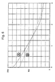
- Fig. 4 is a plot illustrating the calculated effect on the mean water vapour content of gas within the cavern of halving (see curve B) the total initial amount of water in/on the inner surfaces of the cavern (and thus halving the thickness of the water film that this would correspond to) relative to that for curve A (other variables, as well as conditions for curve A, as for Fig. 3).
- Horizontal axis time (in years); vertical axis: water vapour content of gas (in mg/Nm 3 ).
- Fig. 5 is a plot illustrating the calculated effect on the mean water vapour content of gas within the cavern of doubling (see curve B) the "drying time" (t d ; vide infra ) relative to that for curve A (other variables, as well as conditions for curve A, as for Fig. 3).
- Horizontal axis time (in years); vertical axis: water vapour content of gas (in mg/Nm 3 ).
- Fig. 6 is a plot illustrating the calculated effect on the mean water vapour content of gas within the cavern assuming a practical maximum water-vapour content for the "drying" gas (and an initial water vapour content for the gas within the cavern) of 150 mg/Nm 3 (curve B) instead of 180 mg/Nm 3 (curve A), corresponding to a total of 15750 kg of water (as water vapour) in the gas initially present in the cavern (other variables, as well as conditions for curve A, as for Fig. 3).
- Horizontal axis time (in years); vertical axis: water vapour content of gas (in mg/Nm 3 ).
- Fig. 7 is a plot showing calculated water-vapour content for gas within the cavern as a function of depth from the top of the cavern after various accumulated times of operation of the "laminar flow" model process (curve A: after six months; curve B: after 12 months; curve C: after 18 months; curve D: after 24 months). Variables as for Fig.3. Horizontal axis: depth from top of cavern (in meters); vertical axis: water vapour content of gas (in mg/Nm 3 ).
- Fig. 8 is a plot comparing the calculated variation in mean water-vapour content of gas within the cavern as a function of time (curve A) with the calculated curve for time vs. water-vapour content of gas withdrawn from the cavern via a gas-withdrawal conduit having its lower open end positioned at the bottom of the cavern (in this case at a depth of 300 meters from the top of the cavern) (curve B).
- Variables, as well as conditions for curve A as for Fig. 3.
- Horizontal axis time (in years); vertical axis: water vapour content of gas (in mg/Nm 3 ).
- Fig. 9 illustrates schematically the constructional principles underlying an above-ground, well-head manifold system suitable, for example, for use in connection with the application of the method according to the invention to reduction of the water content of a cavern for the storage of natural gas.
- the calculations described here were performed for a hypothetical, vertical, cylindrical cavern.
- the cavern height [which in the case of the "mixing" model is the distance from top to bottom within the cavern (the cavern in this case being equipped with a single conduit for gas introduction and gas withdrawal essentially in the manner illustrated in Fig. 2), and in the case of the "laminar flow” model is the vertical distance between the opening of the gas-introduction conduit and the opening of the gas-withdrawal conduit (the cavern being equipped with such conduits essentially in the manner illustrated in Fig. 1)]
- h was taken to be 300 meters
- the total quantity of gas (expressed in Nm 3 ), V tot , within the cavern was taken to be 105 x 10 6 Nm 3 .
- the cavern was regarded for computational purposes as being divided into a number of layers, the height of each such layer corresponding to the height of the quantity of gas injected into (i.e. introduced into) the cavern in one week; in the present calculations, the quantity of gas injected into the cavern in one week was set equal to 3 x 10 6 Nm 3 .
- the height quantity h inj was regarded as being divided up into layers in the same way as for the "laminar flow" model, i.e. into layers whose height corresponds to that of the amount of gas injected in one week.
- the reference calculations corresponded to injection for a period of four weeks, i.e. h inj was divided up into four layers each having a height of 17.1 m.
- Each round of computations considered a number of gas-withdrawal/gas-injection cycles followed by a "dormancy" period.
- a total of 4 such cycles was considered, each cycle consisting of 2 weeks of withdrawal of a total of 24 x 10 6 Nm 3 of gas from the cavern, followed by 4 weeks of injection of a total of 24 x 10 6 Nm 3 of gas into the cavern.
- the water-vapour content of the withdrawn gas during the first half-week of withdrawal was assumed (on the basis of practical experience with real caverns) to be equal to the water-vapour content of the gas in the uppermost layer, after which complete mixing of the gas in the cavern was assumed to occur (corresponding to the mixing which is expected in a real cavern as a consequence of convection resulting from the temperature drop which will occur as a result of gas withdrawal from the cavern).
- laminar flow of the entering gas i.e. as for the "laminar flow" model
- the water (as water vapour) removed from the cavern walls is assumed to mix fully with the gas in the adjacent (computational) layers. If this assumption should later prove to be invalid, the model can easily be modified so as to incorporate, for example, a simple mathematical function which takes account of an increase in water-vapour content of the gas from the central "vertical" axis of the cavern to the cavern wall.
- a simple mathematical function which takes account of an increase in water-vapour content of the gas from the central "vertical" axis of the cavern to the cavern wall.
- the less efficient mixing to which this latter example of a modified computational model would correspond will result in a lower rate of transport of water away from the cavern walls, and thus slow the entire "drying" process.
- a 1 corresponds to water which is relatively easily removed from the cavern walls, and which is assumed to require a "drying time", denoted t d , which is the time required for removal of 95% of the water by exposure to "dry" gas having a water-vapour content equal to that of the gas as injected into the cavern (C dry w ); a value for C dry w of 20 mg/Nm 3 was employed throughout in the calculations.
- a 2 corresponds to water which is more difficult to remove from the cavern walls, and which is assumed to require a "drying time" which is an order of magnitude greater than for A 1 , i.e. a drying time equal to 10t d .
- the initial values of A 1 and A 2 i.e. A 1 , initial and A 2 , initial, for each layer were assumed to be equal.
- the calculated amount of water transported from the cavern walls to the gas was added to the calculated water-vapour content of the gas at the end of the preceding time increment to give the new, "current" water-vapour content of the gas.
- Figs. 3-8 provide a summary of results obtained on the basis of the computational approach described herein. Whilst a number of simplifying assumptions have (as indicated above) been made in connection with the calculations, the models employed are believed to provide an at least qualitatively reasonably realistic prediction of the results to be expected and advantages to be achieved in the real-life drying of subterranean caverns of the types discussed herein employing the method according to the present invention:
- Figs. 7 and 8 provide an indication not only that a significant reduction in the mean water-vapour content of the gas within a cavern is achievable within an acceptable period of time (e.g., in this model case, a reduction from 180 mg/Nm 3 to ca.
- Fig. 1 shows a cross-sectional diagrammatic representation of a subterranean cavern (1) (such as natural gas storage cavern in a "salt dome") adapted for the performance of the method according to the present invention.
- a conduit (3) such as a "production conduit” ( vide supra )
- a conduit (3) suitably an essentially circularly cylindrical conduit, which extends down to the cavern (1) through a shaft (5) connecting the cavern with the earth's surface (not shown) and which has a lower open end (7) near the shaft's lower end.
- Gas having a higher water-vapour content than the introduced gas is withdrawn from the cavern (1) via a conduit (9) [such as a "brine-withdrawal conduit” ( vide supra )], suitably an essentially circularly cylindrical conduit, which extends within the former conduit (suitably substantially concentrically when both the gas-introduction conduit (3) and the gas-withdrawal conduit (9) are circularly cylindrical conduits] down to a depth within the cavern such that there is a slight clearance between a lower open end (11) of the conduit (9) and a sump seal (13) covering a sump (15) at the bottom of the cavern (1).
- a seal or packer (17) vide supra ) which serves to seal a space (19) (e.g.
- Fig. 2 shows a cross-sectional diagrammatic representation of a subterranean cavern (1) (such as natural gas storage cavern in a "salt dome") in which introduction of relatively dry gas and subsequent withdrawal of gas having a higher water content via a common conduit (3) [such as a "production conduit” ( vide supra )], suitably an essentially circularly cylindrical conduit, is symbolized by downward-pointing and upward-pointing arrows, respectively, near the top of the cavern.
- the conduit (3) extends down to the cavern (1) through a shaft (5) connecting the cavern with the earth's surface (not shown) and has a lower open end (7) near the shaft's lower end.
- This figure also shows a sump seal (13) covering a sump (15) at the bottom of the cavern (1), and further shows a seal or packer (17) ( vide supra ) which serves to seal a space (19) (e.g. an annular space) between the "walls" of the shaft (5) and the gas-introduction conduit (3) in the same manner, and for the same purpose, as described in connection with Fig. 1.
- a seal or packer (17) vide supra
- Fig. 9 illustrates schematically the constructional principles underlying a well-head manifold system suitable for use in connection with a preferred embodiment of the method according to the invention for reduction of the water content of a cavern for the storage of natural gas.
- the left-hand part of the figure shows a well-head arrangement (101) with which uppermost ends of a gas-introduction conduit (3) and a gas-withdrawal conduit (9) [represented by dashed lines, these two conduits most suitably being substantially concentric, circularly cylindrical conduits (cf. the explanation given above in connection with Fig. 1)] communicating with a natural gas storage cavern [such as a cavern illustrated in Fig. 1 (not shown in this figure)], are connected in a gas-tight manner.
- a natural gas storage cavern such as a cavern illustrated in Fig. 1 (not shown in this figure)
- the gas-introduction conduit (3) (represented by heavy dashed lines in the lower left-hand part of the figure) is connected to a lower part of a T-piece (103), and the conduit (9) [represented by lighter dashed lines and extending within and above the conduit (3) and further within the T-piece (103)] is connected to an upper part (shown schematically in the figure as a narrowed upper part) of the T-piece (103).
- the flow of gas from the cavern may be regulated by means of a valve (105), suitably a gate-valve, with which the uppermost part of the T-piece (103) is connected, and the latter valve (105) is in turn preferably further connected to an automatic safety valve (107) which is normally open but which is capable of automatically shutting off the flow of gas emerging from the cavern, e.g. in the event of the flow rate of gas exceeding some preset safety limit.
- a valve (105) suitably a gate-valve, with which the uppermost part of the T-piece (103) is connected, and the latter valve (105) is in turn preferably further connected to an automatic safety valve (107) which is normally open but which is capable of automatically shutting off the flow of gas emerging from the cavern, e.g. in the event of the flow rate of gas exceeding some preset safety limit.
- the safety valve (107) [or, in the absence of such a safety valve, the valve (105)] is connected to a T-piece (109), the uppermost part of which is equipped with an access port or valve (111), suitably a gate-valve.
- the latter access port or valve (111) which is normally closed, permits the lowering [via the T-piece (111) and the valves (107) and (105), and by means of a cable or the like] an explosive charge for shortening the gas-withdrawal conduit (9) ( vide supra ) or a measuring probe or device for measuring the temperature, pressure, water-vapour content or some other parameter of gas within, or below the lower end of, the gas-withdrawal conduit.
- a side-arm of the T-piece (109) is connected to a valve (113), such as a gate-valve, which is normally open and which is connected an instrument manifold (115) comprising measuring devices or probes (not shown) for measuring the temperature, pressure, water-vapour content, etc., of the gas emerging from the well-head (101).
- a valve such as a gate-valve, which is normally open and which is connected an instrument manifold (115) comprising measuring devices or probes (not shown) for measuring the temperature, pressure, water-vapour content, etc., of the gas emerging from the well-head (101).
- the emerging gas passes on via a suitable transport conduit system (117) [the direction of gas flow being indicated by arrows on the uppermost and extreme right-hand sections of the conduit system (117)] equipped with an injection port or valve (119) permitting [if so required, e.g. on the basis of measurements made at the instrument manifold (115)] injection of an inhibitor (such as a glycol) for inhibiting gas hydrate formation in the gas ( vide supra) during its subsequent further handling prior to distribution to the consumer.
- the transport conduit system comprises, apart from a branch comprising the latter-mentioned uppermost and extreme right-hand sections, a branch via which gas arriving at the cavern site from a supplier can enter the transport conduit system (117) and be passed on for introduction into the cavern.
- the transport conduit system (117) is preferably equipped with a pressure-release vent or valve (125) which is normally closed but via which the transport conduit system (117) may, if necessary, be depressurized [e.g. for the purpose of carrying out construction work, repairs, welding etc. in the transport conduit system (117)].
- Gas is introduced into the cavern via an automatic shut-off valve (127), such as a wing-valve, which in turn is connected to a regulating valve (129), suitably a gate-valve, connected to the T-piece (103) via a side-arm thereon [the direction of gas flow towards the valve (127) being indicated by arrows on the sections of the transport conduit system (117) in question].
- the shut-off valve (127) is normally open but is capable of automatically shutting off the flow of gas emerging from the cavern, e.g.
- the withdrawn gas will have to be dried by more "traditional” means, e.g. by counter-current drying using a glycol (in which case the glycol will have to be regenerated, e.g. by distillation).
- the amount of gas injected into and withdrawn from the cavern in each performance of steps (i) and (ii), above, will typically be of the order of 1% (or less) of the total amount of gas within the cavern, i.e. temperature effects arising as a result of withdrawal of such a relatively small proportion of the gas content in the cavern will be negligible.
- Both caverns are equipped with a 13 3/8" casing, a 9 5/8" production conduit and a 4 1/2" brine-withdrawal conduit (the quoted dimensions being external diameters).
Landscapes
- Life Sciences & Earth Sciences (AREA)
- Geology (AREA)
- Engineering & Computer Science (AREA)
- Mining & Mineral Resources (AREA)
- Environmental & Geological Engineering (AREA)
- General Life Sciences & Earth Sciences (AREA)
- Physics & Mathematics (AREA)
- Fluid Mechanics (AREA)
- Geochemistry & Mineralogy (AREA)
- Organic Low-Molecular-Weight Compounds And Preparation Thereof (AREA)
- Filling Or Discharging Of Gas Storage Vessels (AREA)
- Laying Of Electric Cables Or Lines Outside (AREA)
Applications Claiming Priority (3)
| Application Number | Priority Date | Filing Date | Title |
|---|---|---|---|
| DK91565A DK56591D0 (da) | 1991-03-27 | 1991-03-27 | Toerringsfremgangsmaade |
| DK565/91 | 1991-03-27 | ||
| PCT/DK1992/000097 WO1992017682A1 (en) | 1991-03-27 | 1992-03-26 | A method for drying a subterranean cavern |
Publications (2)
| Publication Number | Publication Date |
|---|---|
| EP0577706A1 EP0577706A1 (en) | 1994-01-12 |
| EP0577706B1 true EP0577706B1 (en) | 1996-09-25 |
Family
ID=8094980
Family Applications (2)
| Application Number | Title | Priority Date | Filing Date |
|---|---|---|---|
| EP92908584A Expired - Lifetime EP0577706B1 (en) | 1991-03-27 | 1992-03-26 | A method for drying a subterranean cavern |
| EP92610020A Pending EP0506600A1 (en) | 1991-03-27 | 1992-03-26 | A method for drying a subterranean cavern |
Family Applications After (1)
| Application Number | Title | Priority Date | Filing Date |
|---|---|---|---|
| EP92610020A Pending EP0506600A1 (en) | 1991-03-27 | 1992-03-26 | A method for drying a subterranean cavern |
Country Status (5)
| Country | Link |
|---|---|
| EP (2) | EP0577706B1 (da) |
| AU (1) | AU1645292A (da) |
| DE (1) | DE69214135T2 (da) |
| DK (1) | DK56591D0 (da) |
| WO (1) | WO1992017682A1 (da) |
Cited By (2)
| Publication number | Priority date | Publication date | Assignee | Title |
|---|---|---|---|---|
| EP2580156B1 (en) | 2010-06-10 | 2017-01-04 | Praxair Technology, Inc. | Hydrogen storage method |
| US10173840B2 (en) | 2012-05-25 | 2019-01-08 | Praxair Technology, Inc. | System for operating a hydrogen storage salt cavern |
Families Citing this family (5)
| Publication number | Priority date | Publication date | Assignee | Title |
|---|---|---|---|---|
| DE19857447A1 (de) * | 1998-12-12 | 2000-06-21 | Siegfried Muesig | Anordnung und Verfahren zur Förderung, Speicherung und Verarbeitung von Kohlenwasserstoffen |
| CN108316891B (zh) * | 2017-12-26 | 2020-07-10 | 中国石油天然气集团公司 | 一种控制盐穴储气库中天然气的卤水蒸气含量的方法 |
| CN114088524B (zh) * | 2021-11-18 | 2023-04-28 | 中国电建集团成都勘测设计研究院有限公司 | 高围压层状岩体地下洞室纵轴线布置方位的设计方法 |
| SA123441432B1 (ar) | 2022-03-17 | 2025-01-30 | أرامكو سيرفيسـيز كمبني | طريقة لتعزيز تخزين الغاز تحت السطحي في كهوف الملح |
| CN117027732B (zh) * | 2023-08-28 | 2026-02-10 | 国家石油天然气管网集团有限公司 | 一种盐穴储气库溶腔与储气滚动建设投产的方法 |
Family Cites Families (5)
| Publication number | Priority date | Publication date | Assignee | Title |
|---|---|---|---|---|
| US3438203A (en) * | 1967-08-08 | 1969-04-15 | Shell Oil Co | Method of removing hydrocarbons from salt caverns |
| DE2539720C2 (de) * | 1975-09-06 | 1982-04-29 | Deutsche Texaco Ag, 2000 Hamburg | Verfahren zur Schaumabdeckung der Sumpfoberfläche einer Gaskaverne |
| DE3234914C2 (de) * | 1982-09-21 | 1990-04-19 | Kavernen Bau- Und Betriebs-Gesellschaft Mbh, 3000 Hannover | Verfahren zum Einbringen eines Abdeckmediums in eine Kaverne |
| US4592677A (en) * | 1984-03-21 | 1986-06-03 | Phillips Petroleum Company | Desiccant bed on hydrocarbon charged to and removed from underground (salt) cavern |
| DE3422240A1 (de) * | 1984-06-15 | 1985-12-19 | Albert 4270 Dorsten Romanski | Trocknung von erdgas in kavernen durch direkte oder indirekte kuehlung des gases |
-
1991
- 1991-03-27 DK DK91565A patent/DK56591D0/da not_active Application Discontinuation
-
1992
- 1992-03-26 DE DE69214135T patent/DE69214135T2/de not_active Expired - Fee Related
- 1992-03-26 EP EP92908584A patent/EP0577706B1/en not_active Expired - Lifetime
- 1992-03-26 WO PCT/DK1992/000097 patent/WO1992017682A1/en not_active Ceased
- 1992-03-26 AU AU16452/92A patent/AU1645292A/en not_active Abandoned
- 1992-03-26 EP EP92610020A patent/EP0506600A1/en active Pending
Cited By (3)
| Publication number | Priority date | Publication date | Assignee | Title |
|---|---|---|---|---|
| EP2580156B1 (en) | 2010-06-10 | 2017-01-04 | Praxair Technology, Inc. | Hydrogen storage method |
| US10017324B2 (en) | 2010-06-10 | 2018-07-10 | Praxair Technology, Inc. | Hydrogen storage method and system |
| US10173840B2 (en) | 2012-05-25 | 2019-01-08 | Praxair Technology, Inc. | System for operating a hydrogen storage salt cavern |
Also Published As
| Publication number | Publication date |
|---|---|
| DE69214135D1 (de) | 1996-10-31 |
| DE69214135T2 (de) | 1997-02-13 |
| WO1992017682A1 (en) | 1992-10-15 |
| EP0577706A1 (en) | 1994-01-12 |
| DK56591D0 (da) | 1991-03-27 |
| AU1645292A (en) | 1992-11-02 |
| EP0506600A1 (en) | 1992-09-30 |
Similar Documents
| Publication | Publication Date | Title |
|---|---|---|
| CN113404538B (zh) | 基于煤矿采空区封存二氧化碳的系统及方法 | |
| Bérest et al. | Safety of salt caverns used for underground storage blow out; mechanical instability; seepage; cavern abandonment | |
| Liebscher et al. | Geologic storage of hydrogen–fundamentals, processing, and projects | |
| US3205665A (en) | Underground storage of liquefied gases | |
| Crotogino | Traditional bulk energy storage—Coal and underground natural gas and oil storage | |
| Berest et al. | Tightness tests in salt-cavern wells | |
| EP0577706B1 (en) | A method for drying a subterranean cavern | |
| US4121429A (en) | Underground storage for cold and hot products and methods for constructing same | |
| Pottier et al. | Mass storage of hydrogen | |
| CA1047778A (en) | Underground storage for cold and hot products and methods for constructing same | |
| ES2933503T3 (es) | Almacenamiento de gas en tuneles | |
| GB2457399A (en) | Underground gas storage in flexible, inflatable containers | |
| CN105889746B (zh) | 一种基于硬石膏矿采空区储存天然气的方法 | |
| Moore | Design, installation, and early operation of the Timbalier Bay S-2B (RA) SU gravity-stable, miscible CO2-injection project | |
| Vaskou | Unlined rock caverns: historical &; technical evolutions of a concept for underground storage of hydrocarbons | |
| US3343369A (en) | Method of inhibiting earth subsidence over a cavity | |
| Perez-Perez et al. | Numerical Simulation of H2S and CO2 Generation during SAGD | |
| RU2684553C2 (ru) | Устройство и способ для компенсации добычи природного газа из газового месторождения | |
| US3063246A (en) | Underground storage of hydrocarbons | |
| Sholihin et al. | Remaining Life and Corrosion Rate Prediction of Well Casing Material in the CO2 Environment | |
| RU2011607C1 (ru) | Способ сооружения и эксплуатации подземной емкости для газа на газонаполнительных станциях | |
| Basharova | Features of thermal and hydraulic calculations in designing of cryogenic pipeline for LNG | |
| MURR | Salt Caverns for Petroleum Products | |
| Martin et al. | Materials And Corrosion History With Labarge Madison Production: A 20 Year Story Of Success. | |
| Palmqvist et al. | Design and construction of an LPG rock cavern near by an existing LPG |
Legal Events
| Date | Code | Title | Description |
|---|---|---|---|
| PUAI | Public reference made under article 153(3) epc to a published international application that has entered the european phase |
Free format text: ORIGINAL CODE: 0009012 |
|
| 17P | Request for examination filed |
Effective date: 19931019 |
|
| AK | Designated contracting states |
Kind code of ref document: A1 Designated state(s): DE ES FR GB NL |
|
| XX | Miscellaneous (additional remarks) |
Free format text: VERBUNDEN MIT 92610020.7/0506600 (EUROPAEISCHE ANMELDENUMMER/VEROEFFENTLICHUNGSNUMMER) DURCH ENTSCHEIDUNG VOM 10.11.94. |
|
| 17Q | First examination report despatched |
Effective date: 19941212 |
|
| GRAH | Despatch of communication of intention to grant a patent |
Free format text: ORIGINAL CODE: EPIDOS IGRA |
|
| GRAH | Despatch of communication of intention to grant a patent |
Free format text: ORIGINAL CODE: EPIDOS IGRA |
|
| GRAA | (expected) grant |
Free format text: ORIGINAL CODE: 0009210 |
|
| AK | Designated contracting states |
Kind code of ref document: B1 Designated state(s): DE ES FR GB NL PT |
|
| PG25 | Lapsed in a contracting state [announced via postgrant information from national office to epo] |
Ref country code: FR Effective date: 19960925 Ref country code: ES Free format text: THE PATENT HAS BEEN ANNULLED BY A DECISION OF A NATIONAL AUTHORITY Effective date: 19960925 |
|
| XX | Miscellaneous (additional remarks) |
Free format text: VERBUNDEN MIT 92610020.7/0506600 (EUROPAEISCHE ANMELDENUMMER/VEROEFFENTLICHUNGSNUMMER) DURCH ENTSCHEIDUNG VOM 10.11.94. |
|
| REF | Corresponds to: |
Ref document number: 69214135 Country of ref document: DE Date of ref document: 19961031 |
|
| PG25 | Lapsed in a contracting state [announced via postgrant information from national office to epo] |
Ref country code: PT Effective date: 19961226 |
|
| EN | Fr: translation not filed | ||
| PLBE | No opposition filed within time limit |
Free format text: ORIGINAL CODE: 0009261 |
|
| 26N | No opposition filed | ||
| REG | Reference to a national code |
Ref country code: GB Ref legal event code: IF02 |
|
| PGFP | Annual fee paid to national office [announced via postgrant information from national office to epo] |
Ref country code: GB Payment date: 20030307 Year of fee payment: 12 |
|
| PGFP | Annual fee paid to national office [announced via postgrant information from national office to epo] |
Ref country code: NL Payment date: 20030314 Year of fee payment: 12 |
|
| PGFP | Annual fee paid to national office [announced via postgrant information from national office to epo] |
Ref country code: DE Payment date: 20030326 Year of fee payment: 12 |
|
| PG25 | Lapsed in a contracting state [announced via postgrant information from national office to epo] |
Ref country code: GB Free format text: LAPSE BECAUSE OF NON-PAYMENT OF DUE FEES Effective date: 20040326 |
|
| PG25 | Lapsed in a contracting state [announced via postgrant information from national office to epo] |
Ref country code: NL Free format text: LAPSE BECAUSE OF NON-PAYMENT OF DUE FEES Effective date: 20041001 Ref country code: DE Free format text: LAPSE BECAUSE OF NON-PAYMENT OF DUE FEES Effective date: 20041001 |
|
| GBPC | Gb: european patent ceased through non-payment of renewal fee |
Effective date: 20040326 |
|
| NLV4 | Nl: lapsed or anulled due to non-payment of the annual fee |
Effective date: 20041001 |