EP0577235A1 - Hollow profile for reinforcing motor vehicle doors - Google Patents
Hollow profile for reinforcing motor vehicle doors Download PDFInfo
- Publication number
- EP0577235A1 EP0577235A1 EP93250155A EP93250155A EP0577235A1 EP 0577235 A1 EP0577235 A1 EP 0577235A1 EP 93250155 A EP93250155 A EP 93250155A EP 93250155 A EP93250155 A EP 93250155A EP 0577235 A1 EP0577235 A1 EP 0577235A1
- Authority
- EP
- European Patent Office
- Prior art keywords
- hollow profile
- area
- reinforced
- tubular
- door
- Prior art date
- Legal status (The legal status is an assumption and is not a legal conclusion. Google has not performed a legal analysis and makes no representation as to the accuracy of the status listed.)
- Granted
Links
Images


Classifications
-
- B—PERFORMING OPERATIONS; TRANSPORTING
- B60—VEHICLES IN GENERAL
- B60J—WINDOWS, WINDSCREENS, NON-FIXED ROOFS, DOORS, OR SIMILAR DEVICES FOR VEHICLES; REMOVABLE EXTERNAL PROTECTIVE COVERINGS SPECIALLY ADAPTED FOR VEHICLES
- B60J5/00—Doors
- B60J5/04—Doors arranged at the vehicle sides
- B60J5/042—Reinforcement elements
- B60J5/0422—Elongated type elements, e.g. beams, cables, belts or wires
- B60J5/0438—Elongated type elements, e.g. beams, cables, belts or wires characterised by the type of elongated elements
- B60J5/0443—Beams
- B60J5/0444—Beams characterised by a special cross section
Definitions
- the invention relates to a hollow profile for the reinforcement of a motor vehicle door according to the preamble of the main claim.
- Door reinforcements serve to secure the passenger compartment of a passenger car by stiffening the entire door structure and absorbing a considerable amount of deformation work.
- the door amplifier is attached to the inside of the vehicle door using various techniques.
- One of the usual methods is the forming of the pipe or profile ends and the making of a hole in the formed area (see brochure MW "Door reinforcement pipes made of high-strength fine-grained steel for the automotive industry", 1988 edition).
- the door reinforcement profile is attached directly to the door using standard fastening elements such as screws or rivets.
- Another possibility is to weld a holding plate to both pipe or profile ends and to connect them to the door using resistance welding.
- the object of the invention is to provide an improved hollow profile for the reinforcement of a motor vehicle door, which can be connected inexpensively to the door and whose inner surface can be treated in a simple manner.
- An essential feature of the improved hollow profile is the double-walled reinforcement in the fastening area, which extends perpendicular to the direction of loading.
- This reinforcement area is adjoined in the same direction, ie perpendicular to the direction of loading, by an approximately tubular area which is open at both ends when viewed in the longitudinal direction.
- the profile which in this form extends over the entire length, can be attached directly to the door in the reinforcement area, be it by welding or by screwing or by riveting.
- the most varied variants of this hollow profile according to the invention result.
- a particularly intimate connection to the door is achieved when the contour in the longitudinal direction of the profile is adapted to the contour of the door.
- the proposed profile has the advantage that the necessary lateral installation space is small and it is not necessary to reshape the profile at the ends.
- the profile which is open at both ends, can be surface-treated in a simple manner.
- the profiles can be stained, primed and then painted in a short cycle. This is important for long-term rust protection, since there is always moisture in the space between the motor vehicle doors.
- a first simple embodiment of the hollow profile 1 according to the invention is shown in cross section in FIG.
- the example has a reinforced double-walled area 2, which for fastening this hollow profile 1 to the inside of the not shown here Serves motor vehicle door and an adjoining approximately tubular region 3.
- This area 3 serves to absorb the impact energy.
- the profile 1 is arranged in the motor vehicle door so that the direction of loading, shown here by the arrow 4, is perpendicular to the main axis 5 of the profile 1.
- the depth of the profile 1 is determined by the outer dimension 6 of the tubular region 3. It is easy to see that this dimension 6 can be reduced in that the tubular area 3, comparable to that shown in FIG. 4, is more oval, the long axis of the oval being in the main axis 5.
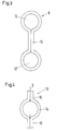
- FIGS. 2 and 3 show two further embodiments in the same cross section as FIG. 1.
- the hollow profile 7 or 8 each has a reinforced area 9 or 10 and two adjoining approximately tubular areas 11, 11 'or 12, 12'.
- the main axis of these profiles 7, 8 lies in relation to the load direction 4 exactly as shown in the example according to FIG. 1, so that repetition is not necessary.
- the profile 7 can be arranged in the door the other way round, for example in mirror image of the main axis.
- FIGS. 4 to 6 show three further exemplary embodiments in which two reinforced areas are combined with a tubular area.
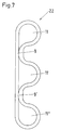
- the hollow profile 13 shown in FIG. 4 is symmetrical, so that the tubular region 14 and the two reinforced regions 15, 15 'lie symmetrically to the main axis 5.
- the vertical regions 18, 18 'and 19, 19' are asymmetrical to the respective tubular regions 20 and 21.
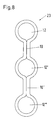
- the exemplary embodiments 22, 23 shown in FIGS. 7 and 8 can be derived directly from those shown in FIGS. 2 and 3, only with the difference that these two reinforced regions 9, 9 'and 10, 10' and a total of three tubular ones Have areas 11, 11 ', 11' 'or 12, 12', 12 ''.
- FIG. 9 Another variant of FIG. 4 is shown in FIG. 9.
- This hollow profile 24 has three reinforced areas 15, 15 ', 15' 'and two tubular areas 14, 14'.
- Figure 10 shows a variant of the embodiment shown in Figure 3.
- This hollow profile 25 also has only one reinforced region 26, each with an adjoining tubular region 12, 12 '.
- the difference from the embodiment according to FIG. 3 is that in the reinforced area 26 the double wall does not lie directly on top of one another, but is at a slight distance 27. This has proven to be advantageous in the manufacture of such a profile.
- This distance also has the advantage that when the two slightly apart wall regions are pressed together, the hollow profile 26 is pretensioned, which has a favorable effect on its deformation behavior in the event of an impact.
- This variant can also be used for similarly designed hollow profiles, for example according to FIG. 2, FIG. 22, FIG. 23 and FIG.
Abstract
Description
Die Erfindung betrifft ein Hohlprofil für die Verstärkung einer Kraftfahrzeugtür gemäß dem Gattungsbegriff des Hauptanspruches.The invention relates to a hollow profile for the reinforcement of a motor vehicle door according to the preamble of the main claim.
Türverstärker dienen zur Sicherung des Fahrgastraumes eines Personenkraftwagens, indem sie die gesamte Türkonstruktion versteifen und einen erheblichen Anteil an Verformungsarbeit aufnehmen. Die Befestigung des Türverstärkers auf der Innenseite der Fahrzeugtür erfolgt mit verschiedenen Techniken. Eine der üblichen Verfahren ist die Umformung der Rohr- bzw. Profilenden und die Anbringung einer Bohrung im umgeformten Bereich (siehe Prospekt MW "Türverstärkerrohre aus hochfestem feinkörnigen Stahl für die Automobilindustrie", Ausgabe 1988). In diesem Fall wird das Türverstärkerprofil unmittelbar mit üblichen Befestigungselementen wie Schrauben oder Nieten an der Tür befestigt. Eine andere Möglichkeit besteht darin, ein Halteblech an beide Rohr- bzw. Profilenden anzuschweißen und diese mittels Widerstandsschweißen mit der Tür zu verbinden.Door reinforcements serve to secure the passenger compartment of a passenger car by stiffening the entire door structure and absorbing a considerable amount of deformation work. The door amplifier is attached to the inside of the vehicle door using various techniques. One of the usual methods is the forming of the pipe or profile ends and the making of a hole in the formed area (see brochure MW "Door reinforcement pipes made of high-strength fine-grained steel for the automotive industry", 1988 edition). In this case, the door reinforcement profile is attached directly to the door using standard fastening elements such as screws or rivets. Another possibility is to weld a holding plate to both pipe or profile ends and to connect them to the door using resistance welding.
Das letztgenannte Verfahren ist recht aufwendig und hat den Nachteil, daß die Verbindung Tür-Profil im Hinblick auf die gewünschte Steifigkeit nicht optimal ist. Für die an den Enden geschlossenen Türverstärkerprofile ist weiterhin nachteilig, daß die innere Oberfläche der Profile nur schwer oder gar nicht oberflächenbehandelt werden kann.The latter method is quite complex and has the disadvantage that the door-profile connection is not optimal with regard to the desired rigidity. For the door reinforcement profiles which are closed at the ends, it is also disadvantageous that the inner surface of the profiles can be surface-treated only with difficulty or not at all.
Aufgabe der Erfindung ist es, ein verbessertes Hohlprofil für die Verstärkung einer Kraftfahrzeugtür anzugeben, das kostengünstig mit der Tür verbindbar ist und dessen innere Oberfläche in einfacher Weise behandelt werden kann.The object of the invention is to provide an improved hollow profile for the reinforcement of a motor vehicle door, which can be connected inexpensively to the door and whose inner surface can be treated in a simple manner.
Diese Aufgabe wird mit den im kennzeichnenden Teil des Hauptanspruches angegebenen Merkmalen gelöst. Vorteilhafte Weiterbildungen sind Bestandteil von Unteransprüchen.This object is achieved with the features specified in the characterizing part of the main claim. Advantageous further developments are part of subclaims.
Wesentliches Merkmal des verbesserten Hohlprofiles ist die doppelwandige Verstärkung im Befestigungsbereich, die sich senkrecht zur Belastungsrichtung erstreckt. An diesen Verstärkungsbereich schließt sich in der gleichen Richtung, d. h. senkrecht zur Belastungsrichtung ein etwa rohrförmiger Bereich an, der in Längsrichtung gesehen an beiden Enden offen ist. Das Profil, das sich in dieser Form über die ganze Länge erstreckt, kann im Verstärkungsbereich unmittelbar an der Tür befestigt werden, sei es durch Schweißen oder durch Schrauben oder durch Nieten. Je nach Anordnung einer oder mehrerer doppelwandiger Verstärkungsbereiche in Verbindung mit einem oder mehreren rohrförmigen Bereichen ergeben sich die unterschiedlichsten Varianten dieses erfindungsgemäßen Hohlprofiles. Eine besonders innige Verbindung zur Tür wird dann erreicht, wenn die Kontur in Längsrichtung des Profiles dem Konturverlauf der Tür angepaßt ist.An essential feature of the improved hollow profile is the double-walled reinforcement in the fastening area, which extends perpendicular to the direction of loading. This reinforcement area is adjoined in the same direction, ie perpendicular to the direction of loading, by an approximately tubular area which is open at both ends when viewed in the longitudinal direction. The profile, which in this form extends over the entire length, can be attached directly to the door in the reinforcement area, be it by welding or by screwing or by riveting. Depending on the arrangement of one or more double-walled reinforcement areas in connection with one or more tubular areas, the most varied variants of this hollow profile according to the invention result. A particularly intimate connection to the door is achieved when the contour in the longitudinal direction of the profile is adapted to the contour of the door.
Das vorgeschlagene Profil hat den Vorteil, daß der notwendige seitliche Bauraum gering und eine Umformung des Profiles an den Enden nicht erforderlich ist. Außerdem kann das an den beiden Enden offene Profil in einfacher Weise oberflächenbehandelt werden. Beispielsweise können die Profile in kurzer Taktzeit gebeizt, grundiert und anschließend lackiert werden. Das ist im Hinblick für einen langfristigen Rostschutz von Bedeutung, da im Zwischenraum der Kraftfahrzeugtür immer Feuchtigkeit vorhanden ist.The proposed profile has the advantage that the necessary lateral installation space is small and it is not necessary to reshape the profile at the ends. In addition, the profile, which is open at both ends, can be surface-treated in a simple manner. For example, the profiles can be stained, primed and then painted in a short cycle. This is important for long-term rust protection, since there is always moisture in the space between the motor vehicle doors.
In der Zeichnung wird anhand einiger Ausführungsbeispiele das erfindungsgemäße Hohlprofil näher erläutert.
Es zeigen:
- Fig.1
- einen Querschnitt durch eine erste Ausführungsform des erfindungsgemäßen Hohlprofiles mit einem verstärkten und einem rohrförmigen Bereich
- Fig. 2-3
- einen Querschnitt durch zwei weitere Ausführungsformen mit einem verstärkten Bereich und zwei rohrförmigen Bereichen
- Fig. 4-6
- einen Querschnitt durch drei weitere Ausführungsformen mit zwei verstärkten Bereichen und einem rohrförmigen Bereich
- Fig. 7-8
- einen Querschnitt durch zwei weitere Ausführungsformen mit zwei verstärkten und drei rohrförmigen Bereich
- Fig. 9
- einen Querschnitt durch eine Ausführungsform mit drei verstärkten Bereichen und zwei rohrförmigen Bereichen.
- Fig. 10
- ähnlich Fig. 3 mit einem einen Abstand aufweisenden verstärkten Bereich
Show it:
- Fig. 1
- a cross section through a first embodiment of the hollow profile according to the invention with a reinforced and a tubular region
- Fig. 2-3
- a cross section through two further embodiments with a reinforced area and two tubular areas
- Fig. 4-6
- a cross section through three further embodiments with two reinforced areas and a tubular area
- Fig. 7-8
- a cross section through two further embodiments with two reinforced and three tubular areas
- Fig. 9
- a cross section through an embodiment with three reinforced areas and two tubular areas.
- Fig. 10
- similar to Fig. 3 with a spaced reinforced area
In Figur 1 ist im Querschnitt eine erste einfache Ausführungsform des erfindungsgemäßen Hohlprofiles 1 dargestellt. Das Beispiel weist einen verstärkten doppelwandigen Bereich 2 auf, der zur Befestigung dieses Hohlprofiles 1 an der Innenseite der hier nicht dargestellten Kraftfahrzeugtür dient und einen daran anschließenden etwa rohrförmigen Bereich 3 auf. Dieser Bereich 3 dient zur Aufnahme der Aufprallenergie. Das Profil 1 ist so in der Kraftfahrzeugtür angeordnet, daß die Belastungsrichtung, hier dargestellt durch den Pfeil 4, senkrecht zur Hauptachse 5 des Profiles 1 liegt. Die Bautiefe des Profiles 1 wird durch das äußere Maß 6 des rohrförmigen Bereiches 3 bestimmt. Es ist leicht einzusehen, daß man dieses Maß 6 verringern kann, indem der rohrförmige Bereich 3, vergleichbar wie in Figur 4 dargestellt, mehr oval ist, wobei die lange Achse des Ovals in der Hauptachse 5 liegt.A first simple embodiment of the
Die Figuren 2 und 3 zeigen im gleichen Querschnitt wie Fig. 1 zwei weitere Ausführungsformen. In diesen Fällen weist das Hohlprofil 7 bzw. 8 je einen verstärkten Bereich 9 bzw. 10 auf und zwei daran anschließende etwa rohrförmige Bereiche 11,11' bzw. 12,12'. Die Hauptachse dieser Profile 7,8 liegt im Verhältnis zur Belastungrichtung 4 genau wie im Beispiel gemäß Figur 1 dargestellt, so daß sich eine Wiederholung erübrigt. Bei dieser grundsätzlichen Anordnung bedarf es auch keines weiteren Hinweises, daß das Profil 7 beispielsweise spiegelbildlich zur Hauptachse auch anders herum in der Tür angeordnet werden kann.FIGS. 2 and 3 show two further embodiments in the same cross section as FIG. 1. In these cases, the
Die Figuren 4 bis 6 zeigen drei weitere Ausführungsbeispiels, bei denen zwei verstärkte Bereiche mit einem rohrförmigen Bereich kombiniert sind. Das in Figur 4 dargestellte Hohlprofil 13 ist symmetrisch ausgebildet, so daß der rohrförmige Bereich 14 und die zwei verstärkten Bereiche 15,15' symmetrisch zur Hauptachse 5 liegen. Im Unterschied dazu liegen bei den in den Figuren 5 und 6 dargestellten Hohlprofilen 16,17 die vertikalen Bereich 18,18' bzw. 19,19' asymmetrisch zum jeweiligen rohrförmigen Bereich 20 bzw. 21.FIGS. 4 to 6 show three further exemplary embodiments in which two reinforced areas are combined with a tubular area. The
Die in den Figuren 7 und 8 dargestellten Ausführungsbeispiele 22,23 sind direkt ableitbar von denen in den Figuren 2 und 3 dargestellten Beispielen, nur mit dem Unterschied, daß diese zwei verstärkte Bereiche 9,9' bzw. 10,10' und insgesamt drei rohrförmige Bereiche 11,11',11'' bzw. 12,12',12'' aufweisen.The
Eine weitere Variante zu Figur 4 ist in Figur 9 dargestellt. Dieses Hohlprofil 24 weist drei verstärkte Bereiche 15,15',15'' und zwei rohrförmige Bereiche 14,14' auf.Another variant of FIG. 4 is shown in FIG. 9. This
Es erübrigt sich darauf hinzuweisen, daß die in den Figuren 5 und 6 dargestellten Ausführungsformen 16,17 in gleicher Weise variiert werden können wie die letztgenannten.Needless to say, the
Figur 10 zeigt eine Variante der in Figur 3 dargestellten Ausführungsform. Auch dieses Hohlprofil 25 weist nur einen verstärkten Bereich 26 mit je einem daran anschließenden rohrförmigen Bereich 12,12' auf. Der Unterschied zur Ausführungsform gemäß Figur 3 besteht darin, daß im verstärkten Bereich 26 die Doppelwand nicht unmittelbar aufeinanderliegt, sondern einen geringfügigen Abstand 27 aufweist. Dies hat sich bei der Herstellung eines solchen Profiles als vorteilhaft erwiesen. Dieser Abstand hat außerdem den Vorteil, daß beim Zusammenpressen der beiden etwas auseinanderstehenden Wandbereiche das Hohlprofil 26 unter Vorspannung gebracht wird, was sich günstig auf dessen Umformverhalten beim Aufprall auswirkt. Diese Variante ist für ähnlich ausgelegte Hohlprofile beispielsweise gemäß Figur 2, Figur 22, Figur 23 und Figur 24 ebenso anwendbar.Figure 10 shows a variant of the embodiment shown in Figure 3. This
Claims (10)
dadurch gekennzeichnet,
daß das Hohlprofil (1,7,8,13,16,17,22,23,24,25) im Befestigungsbereich doppelwandig verstärkt ist und dieser Bereich senkrecht zur Belastungsrichtung (4) liegt und sich über die ganze Länge des Hohlprofiles erstreckt und der daran anschließende etwa rohrförmige Bereich (3,11,11',11'',12,12',12'',14,14',14'',20,21) an beiden Enden offen ist.Hollow profile for reinforcing a motor vehicle door, in particular a passenger car, which can be fixed on the inside of the vehicle door,
characterized by
that the hollow profile (1,7,8,13,16,17,22,23,24,25) is double-walled in the fastening area and this area is perpendicular to the load direction (4) and extends over the entire length of the hollow profile and the adjoining approximately tubular region (3, 11, 11 ', 11'', 12, 12', 12 '', 14, 14 ', 14'', 20, 21) is open at both ends.
dadurch gekennzeichnet,
daß das Hohlprofil (1,7,8,25) nur einen doppelwandig verstärkten Bereich (2,9,10,26) aufweist.Hollow profile according to claim 1,
characterized by
that the hollow profile (1,7,8,25) has only a double-walled reinforced area (2,9,10,26).
dadurch gekennzeichnet,
daß der verstärkte Bereich (2) oben oder unten liegt und der rohrförmige Bereich (3) sich unmittelbar daran anschließt.Hollow profile according to claim 2,
characterized by
that the reinforced area (2) lies above or below and the tubular area (3) immediately adjoins it.
dadurch gekennzeichnet,
daß der verstärkte Bereich (9,10,26) in der Mitte des Hohlprofiles (7,8,25) liegt und je ein rohrförmiger Bereich (11,11',12,12') sich nach oben oder unten anschließt.Hollow profile according to claim 2,
characterized by
that the reinforced area (9, 10, 26) lies in the middle of the hollow profile (7, 8, 25) and that a tubular area (11, 11 ', 12, 12') adjoins up or down.
dadurch gekennzeichnet,
daß der verstärkte Bereich (26) einen geringfügigen Abstand (27) voneinander aufweist.Hollow profile according to claim 4,
characterized by
that the reinforced region (26) is at a slight distance (27) from one another.
dadurch gekennzeichnet,
daß das Hohlprofil (13,20,21,22,23) zwei doppelwandig verstärkte Bereiche (15,15',18,18',19,19',9,9'10,10') aufweist.Hollow profile according to claim 1,
characterized by
that the hollow profile (13, 20, 21, 22, 23) has two double-walled areas (15, 15 ', 18, 18', 19, 19 ', 9.9, 10, 10').
dadurch gekennzeichnet,
daß der rohrförmige Bereich (14,20,21) in der Mitte liegt und daran sich die zwei verstärkten Bereiche (15,15',18,18',19,19') anschließen.Hollow profile according to claim 6,
characterized by
that the tubular area (14, 20, 21) lies in the middle and the two reinforced areas (15, 15 ', 18, 18', 19, 19 ') adjoin it.
dadurch gekennzeichnet,
daß das Hohlprofil (22,23) drei rohrförmige Bereiche (11,11',11'',12,12',12'') aufweist mit je einem dazwischenliegenden verstärkten Bereich (9,9',10,10').Hollow profile according to claim 6,
characterized,
that the hollow profile (22, 23) has three tubular areas (11, 11 ', 11'', 12, 12', 12 ''), each with an intermediate area (9, 9 ', 10, 10').
dadurch gekennzeichnet,
daß das Hohlprofil (24) drei doppelwandig verstärkte Bereiche (15,15',15'')aufweist.Hollow profile according to claim 1,
characterized by
that the hollow profile (24) has three double-walled reinforced areas (15, 15 ', 15'').
dadurch gekennzeichnet,
daß die Kontur des Hohlprofiles (1,7,8,13,16,17,22,23,24,25) in Längsrichtung dem Konturverlauf der Tür angepaßt ist.Hollow profile according to one of the preceding claims,
characterized by
that the contour of the hollow profile (1,7,8,13,16,17,22,23,24,25) is adapted in the longitudinal direction to the contour of the door.
Applications Claiming Priority (2)
| Application Number | Priority Date | Filing Date | Title |
|---|---|---|---|
| DE9208957U DE9208957U1 (en) | 1992-06-30 | 1992-06-30 | |
| DE9208957U | 1992-06-30 |
Publications (2)
| Publication Number | Publication Date |
|---|---|
| EP0577235A1 true EP0577235A1 (en) | 1994-01-05 |
| EP0577235B1 EP0577235B1 (en) | 1995-12-13 |
Family
ID=6881254
Family Applications (1)
| Application Number | Title | Priority Date | Filing Date |
|---|---|---|---|
| EP93250155A Expired - Lifetime EP0577235B1 (en) | 1992-06-30 | 1993-06-03 | Hollow profile for reinforcing motor vehicle doors |
Country Status (3)
| Country | Link |
|---|---|
| EP (1) | EP0577235B1 (en) |
| DE (2) | DE9208957U1 (en) |
| ES (1) | ES2080583T3 (en) |
Cited By (3)
| Publication number | Priority date | Publication date | Assignee | Title |
|---|---|---|---|---|
| DE4423687A1 (en) * | 1994-07-06 | 1996-01-18 | Bayerische Motoren Werke Ag | Strengthening support as side collision protection in motor vehicle door |
| DE10254027A1 (en) * | 2002-11-20 | 2004-06-03 | Bayerische Motoren Werke Ag | Reinforcement for side wall, e.g. door of vehicle, is attached using screws, rivets or other non-thermal jointing methods |
| US6896314B2 (en) | 2003-03-28 | 2005-05-24 | Shape Corporation | Low-profile high-strength vehicle door beam |
Families Citing this family (1)
| Publication number | Priority date | Publication date | Assignee | Title |
|---|---|---|---|---|
| DE4421934A1 (en) * | 1994-06-23 | 1996-01-04 | Ford Werke Ag | Metallic profile to reinforce a motor vehicle door |
Citations (3)
| Publication number | Priority date | Publication date | Assignee | Title |
|---|---|---|---|---|
| US4838606A (en) * | 1986-09-01 | 1989-06-13 | Nissan Motor Co., Ltd. | Door guard bar |
| US4948196A (en) * | 1987-06-23 | 1990-08-14 | Hashimoto Forming Industry Co., Ltd. | Protective beam for automobile side doors |
| US5026111A (en) * | 1989-10-16 | 1991-06-25 | Excel Industries, Inc. | Vehicle door structure with improved energy absorption characteristics |
-
1992
- 1992-06-30 DE DE9208957U patent/DE9208957U1/de not_active Expired - Lifetime
-
1993
- 1993-06-03 ES ES93250155T patent/ES2080583T3/en not_active Expired - Lifetime
- 1993-06-03 EP EP93250155A patent/EP0577235B1/en not_active Expired - Lifetime
- 1993-06-03 DE DE59301150T patent/DE59301150D1/en not_active Expired - Fee Related
Patent Citations (3)
| Publication number | Priority date | Publication date | Assignee | Title |
|---|---|---|---|---|
| US4838606A (en) * | 1986-09-01 | 1989-06-13 | Nissan Motor Co., Ltd. | Door guard bar |
| US4948196A (en) * | 1987-06-23 | 1990-08-14 | Hashimoto Forming Industry Co., Ltd. | Protective beam for automobile side doors |
| US5026111A (en) * | 1989-10-16 | 1991-06-25 | Excel Industries, Inc. | Vehicle door structure with improved energy absorption characteristics |
Cited By (5)
| Publication number | Priority date | Publication date | Assignee | Title |
|---|---|---|---|---|
| DE4423687A1 (en) * | 1994-07-06 | 1996-01-18 | Bayerische Motoren Werke Ag | Strengthening support as side collision protection in motor vehicle door |
| DE10254027A1 (en) * | 2002-11-20 | 2004-06-03 | Bayerische Motoren Werke Ag | Reinforcement for side wall, e.g. door of vehicle, is attached using screws, rivets or other non-thermal jointing methods |
| DE10254027B4 (en) * | 2002-11-20 | 2011-06-16 | Bayerische Motoren Werke Aktiengesellschaft | Motor vehicle with a side wall |
| US6896314B2 (en) | 2003-03-28 | 2005-05-24 | Shape Corporation | Low-profile high-strength vehicle door beam |
| US7055886B2 (en) * | 2003-03-28 | 2006-06-06 | Shape Corporation | Low-profile high-strength vehicle door beam |
Also Published As
| Publication number | Publication date |
|---|---|
| DE59301150D1 (en) | 1996-01-25 |
| ES2080583T3 (en) | 1996-02-01 |
| EP0577235B1 (en) | 1995-12-13 |
| DE9208957U1 (en) | 1992-09-10 |
Similar Documents
| Publication | Publication Date | Title |
|---|---|---|
| EP0479401B1 (en) | Impact beam | |
| DE4031678C2 (en) | Reinforcing element for the body of an automobile | |
| DE102008056507A1 (en) | Automotive body for motor vehicle, particularly for vehicle assembly, has A-column or vehicle column, which is connected with vehicle sillboard | |
| EP2994367A1 (en) | Column for a motor vehicle body shell structure, method for the production of a column and motor vehicle body shell structure | |
| DE3622483A1 (en) | BUMPER FOR VEHICLES | |
| DE102009047951A1 (en) | Column i.e. B-column, for hybrid motor vehicle i.e. passenger car, has outer shell made of aluminum-based alloy and connected with inner shell, and reinforcing part made of aluminum-based alloy and connected with outer wall of outer shell | |
| EP1931557A1 (en) | Vehicle body composed of at least two prefabricated subassemblies, and method for the production thereof | |
| DE60002179T2 (en) | BUMPER | |
| DE19852976B4 (en) | Door frame for a passenger car | |
| DE102007062597A1 (en) | Bodywork unit for bodywork of a motor vehicle, has formed sheet metal plate formed as tailored blank, and has area of lower ductility and area of higher ductility after forming process | |
| EP0577235B1 (en) | Hollow profile for reinforcing motor vehicle doors | |
| DE19946013B4 (en) | Side frame for a self-supporting body of a motor vehicle | |
| EP0109577A1 (en) | Execution form of sheet steel for mud guards, particularly for lorries | |
| DE102015204917A1 (en) | Side door for a vehicle and vehicle with such a side door | |
| DE10348354A1 (en) | Body structure for a motor vehicle comprises a wheel house having an inner wall that is reinforced toward a transverse beam in a base part and over the inner wall of a rear side part toward a rear pillar | |
| DE102006006680A1 (en) | Sill board system for motor vehicle, has sheet metal part whose cross section is attribute to basic geometry of numeric character with closed profile, and flange that is attribute to profile and aligned in vehicle`s vertical direction | |
| DE102013107179A1 (en) | Shock absorbing device for a motor vehicle | |
| EP0584898B1 (en) | Impact beam for a door of a motor vehicle | |
| EP1764286B1 (en) | Vehicle chassis pillar | |
| EP0733540B1 (en) | Hollow beam for a structural frame of a motor vehicle | |
| DE19929872B4 (en) | Shaft strip for a motor vehicle door and method for producing a shaft strip | |
| DE10116437B4 (en) | Body of a vehicle | |
| DE102006002422B4 (en) | Vehicle body structure | |
| DE102009047956A1 (en) | Pillar i.e. B-pillar, for motor vehicle, has outer shell made of steel and connected with inner shell, and reinforcing part made of high-strength aluminum-based alloy and connected with inner shell or reinforcing shell | |
| DE10327194A1 (en) | Connecting arrangement in the roof area of a passenger car |
Legal Events
| Date | Code | Title | Description |
|---|---|---|---|
| PUAI | Public reference made under article 153(3) epc to a published international application that has entered the european phase |
Free format text: ORIGINAL CODE: 0009012 |
|
| AK | Designated contracting states |
Kind code of ref document: A1 Designated state(s): DE ES FR GB IT |
|
| 17P | Request for examination filed |
Effective date: 19931124 |
|
| 17Q | First examination report despatched |
Effective date: 19950516 |
|
| GRAA | (expected) grant |
Free format text: ORIGINAL CODE: 0009210 |
|
| AK | Designated contracting states |
Kind code of ref document: B1 Designated state(s): DE ES FR GB IT |
|
| ET | Fr: translation filed | ||
| REF | Corresponds to: |
Ref document number: 59301150 Country of ref document: DE Date of ref document: 19960125 |
|
| REG | Reference to a national code |
Ref country code: ES Ref legal event code: FG2A Ref document number: 2080583 Country of ref document: ES Kind code of ref document: T3 |
|
| ITF | It: translation for a ep patent filed |
Owner name: GUZZI E RAVIZZA S.R.L. |
|
| GBT | Gb: translation of ep patent filed (gb section 77(6)(a)/1977) |
Effective date: 19960314 |
|
| PGFP | Annual fee paid to national office [announced via postgrant information from national office to epo] |
Ref country code: FR Payment date: 19960521 Year of fee payment: 4 |
|
| PGFP | Annual fee paid to national office [announced via postgrant information from national office to epo] |
Ref country code: ES Payment date: 19960618 Year of fee payment: 4 |
|
| PGFP | Annual fee paid to national office [announced via postgrant information from national office to epo] |
Ref country code: DE Payment date: 19960715 Year of fee payment: 4 |
|
| PLBE | No opposition filed within time limit |
Free format text: ORIGINAL CODE: 0009261 |
|
| STAA | Information on the status of an ep patent application or granted ep patent |
Free format text: STATUS: NO OPPOSITION FILED WITHIN TIME LIMIT |
|
| 26N | No opposition filed | ||
| PG25 | Lapsed in a contracting state [announced via postgrant information from national office to epo] |
Ref country code: GB Effective date: 19970603 |
|
| PG25 | Lapsed in a contracting state [announced via postgrant information from national office to epo] |
Ref country code: ES Free format text: LAPSE BECAUSE OF EXPIRATION OF PROTECTION Effective date: 19970604 |
|
| REG | Reference to a national code |
Ref country code: FR Ref legal event code: TP |
|
| GBPC | Gb: european patent ceased through non-payment of renewal fee |
Effective date: 19970603 |
|
| PG25 | Lapsed in a contracting state [announced via postgrant information from national office to epo] |
Ref country code: FR Free format text: LAPSE BECAUSE OF NON-PAYMENT OF DUE FEES Effective date: 19980227 |
|
| PG25 | Lapsed in a contracting state [announced via postgrant information from national office to epo] |
Ref country code: DE Free format text: LAPSE BECAUSE OF NON-PAYMENT OF DUE FEES Effective date: 19980303 |
|
| REG | Reference to a national code |
Ref country code: FR Ref legal event code: ST |
|
| REG | Reference to a national code |
Ref country code: FR Ref legal event code: ST |
|
| REG | Reference to a national code |
Ref country code: ES Ref legal event code: FD2A Effective date: 20000301 |
|
| PG25 | Lapsed in a contracting state [announced via postgrant information from national office to epo] |
Ref country code: IT Free format text: LAPSE BECAUSE OF NON-PAYMENT OF DUE FEES;WARNING: LAPSES OF ITALIAN PATENTS WITH EFFECTIVE DATE BEFORE 2007 MAY HAVE OCCURRED AT ANY TIME BEFORE 2007. THE CORRECT EFFECTIVE DATE MAY BE DIFFERENT FROM THE ONE RECORDED. Effective date: 20050603 |