EP0577037A1 - Rotatory basket, front loaded washing machine - Google Patents
Rotatory basket, front loaded washing machine Download PDFInfo
- Publication number
- EP0577037A1 EP0577037A1 EP93110256A EP93110256A EP0577037A1 EP 0577037 A1 EP0577037 A1 EP 0577037A1 EP 93110256 A EP93110256 A EP 93110256A EP 93110256 A EP93110256 A EP 93110256A EP 0577037 A1 EP0577037 A1 EP 0577037A1
- Authority
- EP
- European Patent Office
- Prior art keywords
- bowl
- washing
- band
- machine according
- ribs
- Prior art date
- Legal status (The legal status is an assumption and is not a legal conclusion. Google has not performed a legal analysis and makes no representation as to the accuracy of the status listed.)
- Granted
Links
Images


Classifications
-
- D—TEXTILES; PAPER
- D06—TREATMENT OF TEXTILES OR THE LIKE; LAUNDERING; FLEXIBLE MATERIALS NOT OTHERWISE PROVIDED FOR
- D06F—LAUNDERING, DRYING, IRONING, PRESSING OR FOLDING TEXTILE ARTICLES
- D06F37/00—Details specific to washing machines covered by groups D06F21/00 - D06F25/00
- D06F37/26—Casings; Tubs
- D06F37/261—Tubs made by a specially selected manufacturing process or characterised by their assembly from elements
-
- D—TEXTILES; PAPER
- D06—TREATMENT OF TEXTILES OR THE LIKE; LAUNDERING; FLEXIBLE MATERIALS NOT OTHERWISE PROVIDED FOR
- D06F—LAUNDERING, DRYING, IRONING, PRESSING OR FOLDING TEXTILE ARTICLES
- D06F37/00—Details specific to washing machines covered by groups D06F21/00 - D06F25/00
- D06F37/20—Mountings, e.g. resilient mountings, for the rotary receptacle, motor, tub or casing; Preventing or damping vibrations
- D06F37/22—Mountings, e.g. resilient mountings, for the rotary receptacle, motor, tub or casing; Preventing or damping vibrations in machines with a receptacle rotating or oscillating about a horizontal axis
-
- D—TEXTILES; PAPER
- D06—TREATMENT OF TEXTILES OR THE LIKE; LAUNDERING; FLEXIBLE MATERIALS NOT OTHERWISE PROVIDED FOR
- D06F—LAUNDERING, DRYING, IRONING, PRESSING OR FOLDING TEXTILE ARTICLES
- D06F37/00—Details specific to washing machines covered by groups D06F21/00 - D06F25/00
- D06F37/26—Casings; Tubs
- D06F37/264—Tubs provided with reinforcing structures, e.g. ribs, inserts, braces
-
- D—TEXTILES; PAPER
- D06—TREATMENT OF TEXTILES OR THE LIKE; LAUNDERING; FLEXIBLE MATERIALS NOT OTHERWISE PROVIDED FOR
- D06F—LAUNDERING, DRYING, IRONING, PRESSING OR FOLDING TEXTILE ARTICLES
- D06F37/00—Details specific to washing machines covered by groups D06F21/00 - D06F25/00
- D06F37/26—Casings; Tubs
- D06F37/267—Tubs specially adapted for mounting thereto components or devices not provided for in preceding subgroups
- D06F37/268—Tubs specially adapted for mounting thereto components or devices not provided for in preceding subgroups for suspension devices
Definitions
- This invention refers to an improved washing machine. More in detail, this invention refers to a rotatory basket front loaded washing machine.
- the wash-bowl where the basket is housed is connected to the framework in several points.
- connection is obtained on the opposite upper and lower fronts of the bowl by means of connecting elements, which may be either springs or dampers and brake-equipped tie-rods. These elements permit the bowl to oscillate during the operation of the machine.
- the rotation of the basket during the washing and centrifugation stages causes the loss of balance of said basket and, as a consequence, of the bowl to which it is connected.
- the presence of the connection elements prevents the transmission of the oscillation to the load-bearing structure of the machine and permits to keep the bowl constantly aligned along its ideal oscillation plane.
- connection of the springs and brake-equipped tie-rods is generally obtained by means of metal supports provided with housings within which the opposite end of the above mentioned elements are housed and tied.
- the supports are connected by welding to the bowl in the pre-fixed positions; such welding operation requires that the bowl be constituted by plate having an adequate thickness, generally 0.8 mm at least.
- Object of this invention is to obviate the above mentioned drawbacks.
- object of this invention is the realization of an improved washing-machine, wherein the wash-bowl can be connected to the framework of the mashine without requiring the provision of independent metal supports and their welding to the bowl.
- Still another object of this invention is the realization of a rotatory basket, front-loaded washing-machine in which a support that does not require welding interventions or direct connections to the framework of the machine is provided for the power unit.
- washing-machine subject matter of this invention which comprises: a cylindrical wash-bowl connected with springs or dampers and brake-equipped tie-rods to the framework of the machine, and provided with notches along its perimeter; a rotatory basket placed inside said bowl and a flexible band fitted on and fixed all around said bowl, and provided with opposite supports for the connection of one end of said dampers and tie-rods and, at least on a front, with two or more longitudinal ribs which fit into the corresponding notches of bowl (10).
- the bowl notches are at least two, and preferably grouped at equidistant couples.
- connection operation of the wash-bowl to the machine framework can be performed quickly, easily and in any wished position; the bowl may have a reduced thickness; absence of multiple supports and associated welding interventions for the same, which, as known, involves remarkable production savings.
- the washing machine of this invention comprises a wash-bowl globally indicated with (10), of a basically cylindrical form and preferably made of enameled or varnished metal.
- Said bowl is provided all around with a flexible band (12) externally fitted on, in correspondence of the "X" vertical axis.
- Said band which is preferably made of steel, has a basically rectangular regular development, a limited height ( ), comprised, for instance, between 50 and 200 mm, its length is slightly shorter than the external circumference of the bowl (10) and its thickness is preferably comprised between 1 and 3 mm. Such thickness may also be greater, especially when a material other than steel is utilized for its making.
- the flexible band (12) may also be made of fiberglass-reinforced polypropropylene.
- Said flexible band (12) which is placed in contact with bowl (10) and circumscribes it perimetrally, delimitating it along its cylindrical portion, is provided with two or more projecting ribs (14) parallel to one another, which extend preferably for the whole length of said band.
- Said ribs (14) have a trapezoid profile which develops on the front of the band (12) which comes directly in touch with the bowl (10).
- housings (16) complementary to said ribs are obtained, having the form of grooves or annular notches, whose extension is preferably equal to that of the development of said ribs (14).
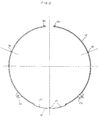
- Fig. 10, 11 and 12 show, as examples, some position possibilities of said band (12) along the perimeter of bowl (10).
- bowl (10) shown on Fig. 10-12 has six housings (16) placed in two groups of 3 housings each, while band (12) is provided with two ribs (14).
- Each of these ribs (14), preferably obtained in correspondence with the side ends of band (12), can be placed in one of the housings (16) of each group. In this way, ribs (14) can abut in three different positions, keeping however constantly the median portion of said band in correspondence of the "X" vertical axis.
- the "X" axis corresponds to bowl (10) of greater diameter, shown on Fig, 10; the (X-1) axis corresponds to the bowl of middle diameter, shown on Fig. 11; and the (X-2) axis corresponds to the smaller diameter bowl, shown on Fig. 12.
- An end of a spring or of a damper (26) is connected to supports (18) - which may be constituted by coupled and centrally drilled tongues - by means of a normal bolt (22) with associated nut (24).
- Tie-rod (28) is integral with supports (20) which can be composed each by a tongue provided with one or more holes.
- Tie-rod (28) is connected to a common dry brake, provided at one end with opposite jaws (30). Said jaws (30) operate by friction on a plate (32) connected to support (20) by means of normal bolts (34) with the associated nut (36).
- tie-rod (28) is connected by welding or the alike to the framework or to the basis of the washing-machine.
- Said support couples (18, 20) are provided on the band (12) in such a way as to be, when band (12) is placed all around bowl (10), in opposite position to one another and basically looking towards the upper and lower fronts of the framework of the washing machine (38).
- the length of band (12) is preferably slightly shorter than the perimeter of bowl (10), so that its ends (46), which, once the placing has taken place, look towards the upper front, are not in touch with one another.
- Said ends of band (12) are preferably bent onto themselves to form as many basically "U"-shaped housings, wherein a connecting and tying member is placed.
- a blocking device (40) is then hooked to the opposite end "U"-bendings, obtained at the ends of the band on making the same.
- Said blocking device (40) comprises a first basically rectangular framework (42) whose side branches show a central swelling (44), looking preferably towards the outside.
- the front cross-bar (54) of said second framework (52) is introduced, during the connection of band (12) around bowl (10), into the "U"-shaped housing of band (12), opposite to that inside which cross-bar (48) is placed.
- the opposite back cross-bar (56) of the second framework (52) constitutes the mesh point for the turnover of said framework (52) which, by rotating anticlockwise according to arrow A (see Fig. 8), lies down along one of the free ends of band (12).
- a support (60) is placed, made of cast or moulded metal, or of plastic material.
- Said support (60) is constituted by a plate (60') provided with two opposite couples of facing drilled extensions (64) which develop towards the outside of the bowl (Fig. 7 shows only a couple of said extensions).
- Said drilled extensions (64) support the stop means that support the power unit (62) of the washing machine.
- the exposed front (60'') of said plate (60') is provided with basically trapezoid housings (16), like those had been formed along the perimeter of bowl (10), for housing the projecting ribs (14) of band (12).
- a "U"-bending is obtained inside which a projecting edge (68) integral with bowl (10) is obtained.
- At least a projection (63) is preferably obtained suitable to prevent possible shiftings of support (60).
- band (12) is brought to circumscribe perimetrally the cylindrical bowl (10).
- the flexibility of the material of which the band is made permits to place the same in touch with bowl (10) and to block it on the latter by means of the blocking device (40) fixed on the free ends (46) looking towards the upper front of bowl (10).
- ribs (14) of band (12) are caused to enter into the corresponding housings (16) provided on the bowl. If support (60) for the power unit is housed lower down, said ribs circumscribe plate (60') of same, entering in the corresponding housings (16') provided along the lower front (60'').
- the already mentioned assembly stage can articulate according to different steps and include, for instance, the prior connection of an end of the springs and dampers to the band and afterwards the blocking of the band to the bowl.
- the projecting ribs could be obtained on the bowl instead of the band, which will have, consequently, the corresponding housings.
- ribs and housings could have configurations, extensions and size different with respect to what has been proposed as an example, while the free ends of the above mentioned band could be connected to one another through rigid means or equivalent stop systems.
Abstract
Description
- This invention refers to an improved washing machine. More in detail, this invention refers to a rotatory basket front loaded washing machine.
- As known, in the rotatory basket washing machines, the wash-bowl where the basket is housed, is connected to the framework in several points. Generally, such connection is obtained on the opposite upper and lower fronts of the bowl by means of connecting elements, which may be either springs or dampers and brake-equipped tie-rods. These elements permit the bowl to oscillate during the operation of the machine.
- The rotation of the basket during the washing and centrifugation stages, especially when there is a limited quantity of linen inside it, causes the loss of balance of said basket and, as a consequence, of the bowl to which it is connected. The presence of the connection elements prevents the transmission of the oscillation to the load-bearing structure of the machine and permits to keep the bowl constantly aligned along its ideal oscillation plane.
- The connection of the springs and brake-equipped tie-rods is generally obtained by means of metal supports provided with housings within which the opposite end of the above mentioned elements are housed and tied.
- However, the provision of said supports on the bowl brings about several drawbacks.
- First of all, in fact, it is necessary to see to the realization of said supports, generally made of plate which is submitted to repeated operations of cutting, bending and drilling.
- Once the supports have been produced, they are connected by welding to the bowl in the pre-fixed positions; such welding operation requires that the bowl be constituted by plate having an adequate thickness, generally 0.8 mm at least.
- Besides, as washing machines are produced according to different types with regard to the capacity and overall dimensions, and as generally the bowl has the same diameter, but a different height and depth, the supports for the springs and tie-rods must be placed and connected to the bowls in different points, according to the depth of same. All these operations involve, as can be easily understood, high costs and long execution times, as well as the compulsory use of specific plants, which are sometimes fitted with interchangeable equipments to be suitable for several types of bowls having different size.
- Object of this invention is to obviate the above mentioned drawbacks.
- More in detail, object of this invention is the realization of an improved washing-machine, wherein the wash-bowl can be connected to the framework of the mashine without requiring the provision of independent metal supports and their welding to the bowl.
- Still another object of this invention is the realization of a rotatory basket, front-loaded washing-machine in which a support that does not require welding interventions or direct connections to the framework of the machine is provided for the power unit.
- These and still other objects are reached by the washing-machine subject matter of this invention, which comprises: a cylindrical wash-bowl connected with springs or dampers and brake-equipped tie-rods to the framework of the machine, and provided with notches along its perimeter; a rotatory basket placed inside said bowl and a flexible band fitted on and fixed all around said bowl, and provided with opposite supports for the connection of one end of said dampers and tie-rods and, at least on a front, with two or more longitudinal ribs which fit into the corresponding notches of bowl (10). The bowl notches are at least two, and preferably grouped at equidistant couples. The advantages obtained through this invention consist basically in that the connection operation of the wash-bowl to the machine framework can be performed quickly, easily and in any wished position; the bowl may have a reduced thickness; absence of multiple supports and associated welding interventions for the same, which, as known, involves remarkable production savings.
- The characteristics and advantages of this invention shall result more clearly from the following description wherein reference is made to the attached drawings which illustrate a preferred, non limitative embodiment, wherein:
- Fig. 1 is a front view of the bowl on which the flexible band incorporating the fasteners for the springs and tie-rods is perimetrally placed and connected;
- Fig. 2 is a front view of the band which is placed all around the bowl;
- Fig. 3 is the front view of a fastener provided on the flexible band for the connection of one end of the brake-equipped tie-rod;
- Fig. 4 is the side view of the fastener of Fig. 3;
- Fig. 5 is the front view of a fastener provided on the flexible band for the connection of an end of the damper;
- Fig. 6 is the side view of the fastener of Fig. 6;
- Fig. 7 is the side view of a sector of the bowl with a flexible band placed on it, with interposition of the motor-support bracket;
- Fig. 8 and 9 are respectively the side and top view of the locking device of the flexible band around the bowl; and
- Fig. 10, 11 and 12 show in detail the position of the flexible band on bowls having different heights.
- With reference to the drawings, the washing machine of this invention comprises a wash-bowl globally indicated with (10), of a basically cylindrical form and preferably made of enameled or varnished metal.
- Said bowl is provided all around with a flexible band (12) externally fitted on, in correspondence of the "X" vertical axis. Said band, which is preferably made of steel, has a basically rectangular regular development, a limited height ( ), comprised, for instance, between 50 and 200 mm, its length is slightly shorter than the external circumference of the bowl (10) and its thickness is preferably comprised between 1 and 3 mm. Such thickness may also be greater, especially when a material other than steel is utilized for its making. The flexible band (12) may also be made of fiberglass-reinforced polypropropylene. Said flexible band (12) which is placed in contact with bowl (10) and circumscribes it perimetrally, delimitating it along its cylindrical portion, is provided with two or more projecting ribs (14) parallel to one another, which extend preferably for the whole length of said band.
- Said ribs (14) have a trapezoid profile which develops on the front of the band (12) which comes directly in touch with the bowl (10). Correspondently, along the circumference of bowl (10), housings (16) complementary to said ribs are obtained, having the form of grooves or annular notches, whose extension is preferably equal to that of the development of said ribs (14).
- The number of notches (16) on the bowl (10) is greater that the number of ribs (14) obtained on band (12), so as to permit to band (12) to be placed in two or more alternative portions, in function of the height of bowl (10). Fig. 10, 11 and 12 show, as examples, some position possibilities of said band (12) along the perimeter of bowl (10). In particular, bowl (10) shown on Fig. 10-12, has six housings (16) placed in two groups of 3 housings each, while band (12) is provided with two ribs (14). Each of these ribs (14), preferably obtained in correspondence with the side ends of band (12), can be placed in one of the housings (16) of each group. In this way, ribs (14) can abut in three different positions, keeping however constantly the median portion of said band in correspondence of the "X" vertical axis.
- In the proposed scheme, the "X" axis corresponds to bowl (10) of greater diameter, shown on Fig, 10; the (X-1) axis corresponds to the bowl of middle diameter, shown on Fig. 11; and the (X-2) axis corresponds to the smaller diameter bowl, shown on Fig. 12.
- Along the exposed front of the flexible band (12) are obtained, during the making of same and through technological operations of moulding, drawing, rolling, pending, if it is of metal, or die-casting, if it is of plastic material, two or more couples of protruting supports (18-20), which form respectively the housings for hooking the end of the springs or the dampers and of the brake-equipped tie-rods, connected to the opposite end with known means (not shown) to the framework of the washing-machine. An end of a spring or of a damper (26) is connected to supports (18) - which may be constituted by coupled and centrally drilled tongues - by means of a normal bolt (22) with associated nut (24).
- The front end of a tie-rod (28) is integral with supports (20) which can be composed each by a tongue provided with one or more holes. Tie-rod (28) is connected to a common dry brake, provided at one end with opposite jaws (30). Said jaws (30) operate by friction on a plate (32) connected to support (20) by means of normal bolts (34) with the associated nut (36).
- At the opposite end, tie-rod (28) is connected by welding or the alike to the framework or to the basis of the washing-machine.
- Said support couples (18, 20) are provided on the band (12) in such a way as to be, when band (12) is placed all around bowl (10), in opposite position to one another and basically looking towards the upper and lower fronts of the framework of the washing machine (38).
- As above specified, the length of band (12) is preferably slightly shorter than the perimeter of bowl (10), so that its ends (46), which, once the placing has taken place, look towards the upper front, are not in touch with one another. Said ends of band (12) are preferably bent onto themselves to form as many basically "U"-shaped housings, wherein a connecting and tying member is placed. A blocking device (40) is then hooked to the opposite end "U"-bendings, obtained at the ends of the band on making the same. Said blocking device (40) comprises a first basically rectangular framework (42) whose side branches show a central swelling (44), looking preferably towards the outside. The front cross-bar (48) of said framework (42), preferably made of metal rod, is introduced into one of the "U"-shaped housings obtained from the bending of one of the mentioned ends (46) of band (12). A second framework (52), always of basically rectangular shape, is articulatably connected to framework (42), in correspondence of the side branch, which develops starting from cross-bar (50). The front cross-bar (54) of said second framework (52) is introduced, during the connection of band (12) around bowl (10), into the "U"-shaped housing of band (12), opposite to that inside which cross-bar (48) is placed. The opposite back cross-bar (56) of the second framework (52) constitutes the mesh point for the turnover of said framework (52) which, by rotating anticlockwise according to arrow A (see Fig. 8), lies down along one of the free ends of band (12).
- Between portion (12') of band (12), devoided of ribs (14) and the lower front of bowl (10) a support (60) is placed, made of cast or moulded metal, or of plastic material. Said support (60) is constituted by a plate (60') provided with two opposite couples of facing drilled extensions (64) which develop towards the outside of the bowl (Fig. 7 shows only a couple of said extensions).
- Said drilled extensions (64) support the stop means that support the power unit (62) of the washing machine.
- The exposed front (60'') of said plate (60') is provided with basically trapezoid housings (16), like those had been formed along the perimeter of bowl (10), for housing the projecting ribs (14) of band (12). In correspondence of at least one end of support (60), a "U"-bending is obtained inside which a projecting edge (68) integral with bowl (10) is obtained.
- On the internal front of portion (12') devoided of ribs (14), at least a projection (63) is preferably obtained suitable to prevent possible shiftings of support (60).
- During the assembly, band (12) is brought to circumscribe perimetrally the cylindrical bowl (10). The flexibility of the material of which the band is made permits to place the same in touch with bowl (10) and to block it on the latter by means of the blocking device (40) fixed on the free ends (46) looking towards the upper front of bowl (10). During this operations, ribs (14) of band (12) are caused to enter into the corresponding housings (16) provided on the bowl. If support (60) for the power unit is housed lower down, said ribs circumscribe plate (60') of same, entering in the corresponding housings (16') provided along the lower front (60'').
- Having placed and blocked band (12) around bowl (10) it is then possible to perform the connection of said bowl to framework (38) of the washing machine. This is obtained by connecting an end of the springs or dampers (26) and of the brake-equipped tie-rods (28) to the housings of supports (18) and (20) which project from the band. The support (60), to which the power unit (62) is advantageously caused to be integral, is interposed and blocked between band (12) and bowl (10).
- Obviously, the already mentioned assembly stage can articulate according to different steps and include, for instance, the prior connection of an end of the springs and dampers to the band and afterwards the blocking of the band to the bowl.
- From the above, one can easily understand the many advantages which can be obtained through this invention.
- In the improved washing-machine subject matter of this invention one needs not welding the supports on the bowl to create the connection points of the springs or dampers and of the brake-equipped tie-rods; besides, particularly advantageous is the position of the support for the power unit, which is interposed and blocked between said flexible band (12) and bowl (10), with no need for direct weldings on the framework of the machine. The provision of a plurality of housings for the ribs of the flexible band along the bowl perimeter permits also to place said band in alternative positions.
- While the invention herein has been illustrated by way of a detailed embodiment, it will be appreciated that the various substitutions of equivalents can be made without departing from the spirit and scope of the invention.
- For instance, the projecting ribs could be obtained on the bowl instead of the band, which will have, consequently, the corresponding housings. Besides, ribs and housings could have configurations, extensions and size different with respect to what has been proposed as an example, while the free ends of the above mentioned band could be connected to one another through rigid means or equivalent stop systems.
- It is understood that these and other substitutions of equivalents fall within the scope of the invention as set forth in the following claims.
Claims (11)
- Rotatory basket, front loaded washing-machine, comprising:- a framework (38);- a cylindrical wash-bowl (10);- a rotatory basket placed inside said bowl (10);- springs or dampers (26) and brake-equipped tie-rods (28) to connect bowl (10) to framework (38);- fastening means for said springs (26) and tie-rods.
- Washing-machine according to claim 1, characterized in that the flexible band (12) is provided with two or more projecting ribs (14) parallel to one another, and, correspondigly, bowl (10) is provided along the circumference of housings (16) shaped as grooves or annular notches complementary to said ribs (14)
- Washing-machine according to claim 2, wherein notches (16) of bowl (10) are more numerous than ribs (14) of band (12), and arranged in separate groups.
- Washing-machine according to claim 2 or 3, wherein ribs (14) have a trapezoid profile and extend for the whole length of the band (10).
- Washing-machine according to any claim whatever of the above ones, wherein the band is of steel, has a rectangular development and a height comprised between 50 and 200 mm, a length a little shorter than the external circumference of bowl (10) and a thickness comprised between 1 and 3 mm.
- Washing-machine according to any claim whatever of the above ones, characterized in that between the flexible band (12) and bowl (10) a support (60) is interposed, constituted by a plate (62), on one front at least of which two or more notches (16') are provided for housing ribs (14) of band (12); said plate being provided with two extensions (64) having with a hole for housing stop means suitable to connect the power unit (62) to said support.
- Washing-machine according to any claim whatever of the above ones, characterized in that the flexible band (12) is shorter than the circumference of bowl (10) and its opposite ends are "U"-bent onto themselves, in the housing formed by said bendings being hooked the means (40) for locking said band to said bowl.
- Washing-machine according to claim 7, charaterized in that said means (40) for locking the flexible band (12) to bowl (10) comprise a couple of metal frameworks (42, 43), articulatably connected to one another.
- Washing-machine according to claim 6, characterized in that support (60) is provided, in correspondence of at least one end, of a "U"-bending wherein a projecting edge (68) integral with bowl (10) is inserted.
- Washing-machine according to any claim whatever of the above ones, characterized in that the flexible band (12) shows a central portion (12') devoided of ribs (18), whose inside front is provided with at least one protrusion (63).
- Washing-machine according to any claim whatever of the above ones, characterized in that the flexible band (12) is made of fiberglass-reinforced polypropylene.
Applications Claiming Priority (2)
| Application Number | Priority Date | Filing Date | Title |
|---|---|---|---|
| ITMI921640 | 1992-07-03 | ||
| ITMI921640A IT1255408B (en) | 1992-07-03 | 1992-07-03 | PERFECTED WASHING MACHINE |
Publications (2)
| Publication Number | Publication Date |
|---|---|
| EP0577037A1 true EP0577037A1 (en) | 1994-01-05 |
| EP0577037B1 EP0577037B1 (en) | 1997-10-29 |
Family
ID=11363621
Family Applications (1)
| Application Number | Title | Priority Date | Filing Date |
|---|---|---|---|
| EP93110256A Expired - Lifetime EP0577037B1 (en) | 1992-07-03 | 1993-06-28 | Rotatory basket, front loaded washing machine |
Country Status (5)
| Country | Link |
|---|---|
| EP (1) | EP0577037B1 (en) |
| AT (1) | ATE159774T1 (en) |
| DE (1) | DE69314859T2 (en) |
| ES (1) | ES2108787T3 (en) |
| IT (1) | IT1255408B (en) |
Cited By (3)
| Publication number | Priority date | Publication date | Assignee | Title |
|---|---|---|---|---|
| KR20040047223A (en) * | 2002-11-29 | 2004-06-05 | 엘지전자 주식회사 | drum washing machine |
| US20100139330A1 (en) * | 2007-04-04 | 2010-06-10 | Bsh Bosch Und Siemens Hausgerate Gmbh | Drum of a machine for the careful treatment for clothes |
| US7976111B2 (en) | 2005-02-02 | 2011-07-12 | Girbau, S.A. | Support structure for a clothes washing machine |
Citations (4)
| Publication number | Priority date | Publication date | Assignee | Title |
|---|---|---|---|---|
| FR1168137A (en) * | 1956-12-13 | 1958-12-04 | App Electr Soc Gen | Improvement in the assembly of washing machines |
| FR1515836A (en) * | 1965-06-25 | 1968-03-08 | Electrochimie Soc | Improvements to machine tanks |
| GB1155774A (en) * | 1966-07-20 | 1969-06-18 | Suspa Federungstech | Washing Machine |
| EP0129769A2 (en) * | 1983-06-22 | 1985-01-02 | INDUSTRIE ZANUSSI S.p.A. | Washing tub for a laundry washing machine |
-
1992
- 1992-07-03 IT ITMI921640A patent/IT1255408B/en active IP Right Grant
-
1993
- 1993-06-28 EP EP93110256A patent/EP0577037B1/en not_active Expired - Lifetime
- 1993-06-28 AT AT93110256T patent/ATE159774T1/en active
- 1993-06-28 ES ES93110256T patent/ES2108787T3/en not_active Expired - Lifetime
- 1993-06-28 DE DE69314859T patent/DE69314859T2/en not_active Expired - Fee Related
Patent Citations (4)
| Publication number | Priority date | Publication date | Assignee | Title |
|---|---|---|---|---|
| FR1168137A (en) * | 1956-12-13 | 1958-12-04 | App Electr Soc Gen | Improvement in the assembly of washing machines |
| FR1515836A (en) * | 1965-06-25 | 1968-03-08 | Electrochimie Soc | Improvements to machine tanks |
| GB1155774A (en) * | 1966-07-20 | 1969-06-18 | Suspa Federungstech | Washing Machine |
| EP0129769A2 (en) * | 1983-06-22 | 1985-01-02 | INDUSTRIE ZANUSSI S.p.A. | Washing tub for a laundry washing machine |
Cited By (3)
| Publication number | Priority date | Publication date | Assignee | Title |
|---|---|---|---|---|
| KR20040047223A (en) * | 2002-11-29 | 2004-06-05 | 엘지전자 주식회사 | drum washing machine |
| US7976111B2 (en) | 2005-02-02 | 2011-07-12 | Girbau, S.A. | Support structure for a clothes washing machine |
| US20100139330A1 (en) * | 2007-04-04 | 2010-06-10 | Bsh Bosch Und Siemens Hausgerate Gmbh | Drum of a machine for the careful treatment for clothes |
Also Published As
| Publication number | Publication date |
|---|---|
| EP0577037B1 (en) | 1997-10-29 |
| IT1255408B (en) | 1995-10-31 |
| ITMI921640A1 (en) | 1994-01-03 |
| DE69314859T2 (en) | 1998-03-05 |
| ITMI921640A0 (en) | 1992-07-03 |
| ATE159774T1 (en) | 1997-11-15 |
| ES2108787T3 (en) | 1998-01-01 |
| DE69314859D1 (en) | 1997-12-04 |
Similar Documents
| Publication | Publication Date | Title |
|---|---|---|
| EP1849905B1 (en) | Washing machine support structure | |
| US4366902A (en) | Shipping system for automatic washer | |
| EP1424429B1 (en) | Washing machine with special cabinet construction | |
| US20110167878A1 (en) | Suspension arrangement for clothes washing machine | |
| US5746070A (en) | Plastic and stainless steel horizontal axis spin tub | |
| US8646190B2 (en) | Laundry dryer | |
| EP1760183B2 (en) | Washing and/or Drying Machine Having a Damper Connecting Structure Including a Reinforcing Portion | |
| EP0577037A1 (en) | Rotatory basket, front loaded washing machine | |
| GB2189511A (en) | A drum housing particularly for washing machines | |
| EP0132805A2 (en) | Stainless steel tub for a laundry washing machine | |
| US20020002847A1 (en) | Washing machine with tilted washing tub | |
| RU2000110733A (en) | CONCRETE RING AS A COUNTERBALANCE ON THE TANK FOR ALKALINE OF THE WASHING MACHINE | |
| US5533367A (en) | Appliance shipping restraint assembly | |
| US4711105A (en) | Washing machine having rotary basket in washing tub | |
| KR100437041B1 (en) | A front cover's installing structure of the drum type washer | |
| EP0315076A2 (en) | Vibration dampening device for a laundry washing machine | |
| ITPN970070A1 (en) | WASHING MACHINE WITH AN IMPROVED ANCHORING OF THE LAVANTE GROUP | |
| FR2663964B3 (en) | DEVICE FOR BALANCING THE BALANCE OF LAUNDRY PARTS DURING SPIN IN PROGRAMMED DRUM WASHING MACHINES. | |
| KR100437040B1 (en) | A top plat installing structure of the drum type washer | |
| EP0104475B1 (en) | Laundry washing machine of the top-charging type provided with a counterweight | |
| US6007473A (en) | Centrifuge with reduced noise generation | |
| KR950008433Y1 (en) | Cup transfering frame for vending machine | |
| JP4150455B2 (en) | Washing machine with improved suspension means for a laundry assembly | |
| JPH0718155B2 (en) | Method for constructing cast-in-place concrete reinforced concrete pile and reinforced basket used for this method | |
| EP0214510A2 (en) | Laundry washing machine |
Legal Events
| Date | Code | Title | Description |
|---|---|---|---|
| PUAI | Public reference made under article 153(3) epc to a published international application that has entered the european phase |
Free format text: ORIGINAL CODE: 0009012 |
|
| AK | Designated contracting states |
Kind code of ref document: A1 Designated state(s): AT BE CH DE DK ES FR GB GR IE LI LU NL PT SE |
|
| RAP1 | Party data changed (applicant data changed or rights of an application transferred) |
Owner name: IAR-SILTAL S.P.A. |
|
| 17P | Request for examination filed |
Effective date: 19940617 |
|
| 17Q | First examination report despatched |
Effective date: 19960207 |
|
| GRAG | Despatch of communication of intention to grant |
Free format text: ORIGINAL CODE: EPIDOS AGRA |
|
| GRAH | Despatch of communication of intention to grant a patent |
Free format text: ORIGINAL CODE: EPIDOS IGRA |
|
| GRAH | Despatch of communication of intention to grant a patent |
Free format text: ORIGINAL CODE: EPIDOS IGRA |
|
| GRAA | (expected) grant |
Free format text: ORIGINAL CODE: 0009210 |
|
| AK | Designated contracting states |
Kind code of ref document: B1 Designated state(s): AT BE CH DE DK ES FR GB GR IE LI LU NL PT SE |
|
| PG25 | Lapsed in a contracting state [announced via postgrant information from national office to epo] |
Ref country code: NL Free format text: LAPSE BECAUSE OF FAILURE TO SUBMIT A TRANSLATION OF THE DESCRIPTION OR TO PAY THE FEE WITHIN THE PRESCRIBED TIME-LIMIT Effective date: 19971029 Ref country code: LI Free format text: LAPSE BECAUSE OF FAILURE TO SUBMIT A TRANSLATION OF THE DESCRIPTION OR TO PAY THE FEE WITHIN THE PRESCRIBED TIME-LIMIT Effective date: 19971029 Ref country code: GR Free format text: LAPSE BECAUSE OF FAILURE TO SUBMIT A TRANSLATION OF THE DESCRIPTION OR TO PAY THE FEE WITHIN THE PRESCRIBED TIME-LIMIT Effective date: 19971029 Ref country code: DK Free format text: LAPSE BECAUSE OF NON-PAYMENT OF DUE FEES Effective date: 19971029 Ref country code: CH Free format text: LAPSE BECAUSE OF FAILURE TO SUBMIT A TRANSLATION OF THE DESCRIPTION OR TO PAY THE FEE WITHIN THE PRESCRIBED TIME-LIMIT Effective date: 19971029 Ref country code: BE Free format text: LAPSE BECAUSE OF FAILURE TO SUBMIT A TRANSLATION OF THE DESCRIPTION OR TO PAY THE FEE WITHIN THE PRESCRIBED TIME-LIMIT Effective date: 19971029 Ref country code: AT Free format text: LAPSE BECAUSE OF FAILURE TO SUBMIT A TRANSLATION OF THE DESCRIPTION OR TO PAY THE FEE WITHIN THE PRESCRIBED TIME-LIMIT Effective date: 19971029 |
|
| REF | Corresponds to: |
Ref document number: 159774 Country of ref document: AT Date of ref document: 19971115 Kind code of ref document: T |
|
| REG | Reference to a national code |
Ref country code: CH Ref legal event code: EP |
|
| REF | Corresponds to: |
Ref document number: 69314859 Country of ref document: DE Date of ref document: 19971204 |
|
| ET | Fr: translation filed | ||
| REG | Reference to a national code |
Ref country code: ES Ref legal event code: FG2A Ref document number: 2108787 Country of ref document: ES Kind code of ref document: T3 |
|
| PG25 | Lapsed in a contracting state [announced via postgrant information from national office to epo] |
Ref country code: SE Effective date: 19980129 Ref country code: PT Free format text: LAPSE BECAUSE OF FAILURE TO SUBMIT A TRANSLATION OF THE DESCRIPTION OR TO PAY THE FEE WITHIN THE PRESCRIBED TIME-LIMIT Effective date: 19980129 |
|
| NLV1 | Nl: lapsed or annulled due to failure to fulfill the requirements of art. 29p and 29m of the patents act | ||
| REG | Reference to a national code |
Ref country code: CH Ref legal event code: PL |
|
| PGFP | Annual fee paid to national office [announced via postgrant information from national office to epo] |
Ref country code: ES Payment date: 19980604 Year of fee payment: 6 |
|
| PGFP | Annual fee paid to national office [announced via postgrant information from national office to epo] |
Ref country code: FR Payment date: 19980611 Year of fee payment: 6 |
|
| PGFP | Annual fee paid to national office [announced via postgrant information from national office to epo] |
Ref country code: GB Payment date: 19980619 Year of fee payment: 6 |
|
| PG25 | Lapsed in a contracting state [announced via postgrant information from national office to epo] |
Ref country code: LU Free format text: LAPSE BECAUSE OF NON-PAYMENT OF DUE FEES Effective date: 19980628 Ref country code: IE Free format text: LAPSE BECAUSE OF NON-PAYMENT OF DUE FEES Effective date: 19980628 |
|
| PGFP | Annual fee paid to national office [announced via postgrant information from national office to epo] |
Ref country code: DE Payment date: 19980727 Year of fee payment: 6 |
|
| PLBE | No opposition filed within time limit |
Free format text: ORIGINAL CODE: 0009261 |
|
| STAA | Information on the status of an ep patent application or granted ep patent |
Free format text: STATUS: NO OPPOSITION FILED WITHIN TIME LIMIT |
|
| 26N | No opposition filed | ||
| PG25 | Lapsed in a contracting state [announced via postgrant information from national office to epo] |
Ref country code: GB Free format text: LAPSE BECAUSE OF NON-PAYMENT OF DUE FEES Effective date: 19990628 |
|
| PG25 | Lapsed in a contracting state [announced via postgrant information from national office to epo] |
Ref country code: ES Free format text: LAPSE BECAUSE OF NON-PAYMENT OF DUE FEES Effective date: 19990629 |
|
| PG25 | Lapsed in a contracting state [announced via postgrant information from national office to epo] |
Ref country code: FR Free format text: THE PATENT HAS BEEN ANNULLED BY A DECISION OF A NATIONAL AUTHORITY Effective date: 19990630 |
|
| GBPC | Gb: european patent ceased through non-payment of renewal fee |
Effective date: 19990628 |
|
| PG25 | Lapsed in a contracting state [announced via postgrant information from national office to epo] |
Ref country code: DE Free format text: LAPSE BECAUSE OF NON-PAYMENT OF DUE FEES Effective date: 20000503 |
|
| REG | Reference to a national code |
Ref country code: FR Ref legal event code: ST |
|
| REG | Reference to a national code |
Ref country code: ES Ref legal event code: FD2A Effective date: 20010503 |