EP0576967B1 - Motorisch angetriebene Pipette - Google Patents
Motorisch angetriebene Pipette Download PDFInfo
- Publication number
- EP0576967B1 EP0576967B1 EP93109949A EP93109949A EP0576967B1 EP 0576967 B1 EP0576967 B1 EP 0576967B1 EP 93109949 A EP93109949 A EP 93109949A EP 93109949 A EP93109949 A EP 93109949A EP 0576967 B1 EP0576967 B1 EP 0576967B1
- Authority
- EP
- European Patent Office
- Prior art keywords
- piston
- knob
- pipette
- movement
- control system
- Prior art date
- Legal status (The legal status is an assumption and is not a legal conclusion. Google has not performed a legal analysis and makes no representation as to the accuracy of the status listed.)
- Expired - Lifetime
Links
- 230000033001 locomotion Effects 0.000 claims abstract description 29
- 238000006073 displacement reaction Methods 0.000 claims abstract description 14
- 239000007788 liquid Substances 0.000 claims description 13
- 230000005540 biological transmission Effects 0.000 claims description 7
- 238000012544 monitoring process Methods 0.000 claims description 5
- 238000000034 method Methods 0.000 claims 1
- 230000008878 coupling Effects 0.000 description 5
- 238000010168 coupling process Methods 0.000 description 5
- 238000005859 coupling reaction Methods 0.000 description 5
- 238000005259 measurement Methods 0.000 description 5
- 238000010586 diagram Methods 0.000 description 2
- 210000005224 forefinger Anatomy 0.000 description 2
- 230000007257 malfunction Effects 0.000 description 2
- 230000000052 comparative effect Effects 0.000 description 1
- 238000010276 construction Methods 0.000 description 1
- 230000007423 decrease Effects 0.000 description 1
- 230000001939 inductive effect Effects 0.000 description 1
- 238000000691 measurement method Methods 0.000 description 1
- 210000003813 thumb Anatomy 0.000 description 1
Images


Classifications
-
- B—PERFORMING OPERATIONS; TRANSPORTING
- B01—PHYSICAL OR CHEMICAL PROCESSES OR APPARATUS IN GENERAL
- B01L—CHEMICAL OR PHYSICAL LABORATORY APPARATUS FOR GENERAL USE
- B01L3/00—Containers or dishes for laboratory use, e.g. laboratory glassware; Droppers
- B01L3/02—Burettes; Pipettes
- B01L3/021—Pipettes, i.e. with only one conduit for withdrawing and redistributing liquids
- B01L3/0217—Pipettes, i.e. with only one conduit for withdrawing and redistributing liquids of the plunger pump type
- B01L3/0227—Details of motor drive means
-
- B—PERFORMING OPERATIONS; TRANSPORTING
- B01—PHYSICAL OR CHEMICAL PROCESSES OR APPARATUS IN GENERAL
- B01L—CHEMICAL OR PHYSICAL LABORATORY APPARATUS FOR GENERAL USE
- B01L2300/00—Additional constructional details
- B01L2300/02—Identification, exchange or storage of information
- B01L2300/025—Displaying results or values with integrated means
- B01L2300/027—Digital display, e.g. LCD, LED
Definitions
- the invention relates to pipettes according to the preamble of Claim 1
- pipettes are used for dosing liquids, which pipettes have a cylinder and therein a piston by means of which the liquid is sucked and discharged.
- the rod of the piston rod extends above the handle of the pipette into a knob, by means of which the piston is moved.
- Pipettes in which the piston is moved by the power of an electric motor are also known. This naturally makes the use of the pipette lighter.
- the US-A-4 821 586 discloses a pipette with the features of the preamble of Claim 1.
- the main parts of the pipette include a body provided with an upper end and a lower end, a cylinder part at the lower end of the body, a piston reciprocating in the cylinder part for sucking and removing liquid, an electric motor and a transmission mechanism for moving the piston, a control system for controlling the piston movement, and a knob slidably and reciprocatively movable in the body, the displacement of which knob by means of the control system determines the piston movement.
- the electric motor can be e.g. a stepping or DC motor.
- the transmission mechanism can be based e.g. on a guide screw and nut or on a rack and pinion.
- the knob has two extreme positions, between which it may be slid.
- the control is preferably arranged such that the knob has an upper position extending from the body and a lower position located more inside relative to the body, which positions also correspond to the upper and lower position of the piston.
- the knob is also connected with a return spring mechanism, which tends to keep the knob in its upper position.
- the knob is then basically of the same type as that used in pipettes operated manually, and its operating mechamism continually gives the user a concrete feeling of the pipetting.
- the knob Since the knob is not mechanically in a transmission relationship with the piston, the knob can be easily positioned in any place on the body, e.g on the side of the body. The possibilities of the construction are thus increased.
- the knob may thus be moved by the forefinger in the cross-direction of the body.
- the piston Most preferably, the piston has still beneath the lower position a discharge position, into which the piston is driven, when the liquid is dosed out of the pipette. This ensures a discharge of the liquid as completely as possible.
- the knob has a discharge position beneath the lower position.
- the knob is most preferably connected with a return spring for the discharge movement, which withstands the pressing of the knob below the lower position. In this way, the user may readily feel, when the knob enters into the lower position.
- the displacement of the knob is most prerably measured by a pulse sensor sensing the direction of movement, by a resistance sensor or an optic sensor.
- a capacitive or an inductive sensor can also be used.
- the information about the displacement is transmitted into the control system, which controls the piston movement in a desired manner.
- the movement limits of the piston can be determined by means of movement limiters, such as stops, limit switches or braking devices, placed on the body or the transmission mechanism.
- the limiter in volume-controllable pipettes is adjustable, whereby the volume to be pipetted may be set as desired.
- the pipette has most preferably a piston-movement monitoring system connected to the control system.
- the system can be based on e.g. a pulse encoder or a tachogenerator.
- the monitoring system enters into the control system an information about the distance travelled by the piston. On the basis of this information, the piston movement can be stopped precisely, when the piston is in the desired location. The piston movement is best stopped by decelarating the rotational speed of the motor. By means of the system, also the movement speed of the piston can be followed, if desired. Also the momentary speed of the piston and the difference between the displacement of the knob and the piston can be used as controlled variables in the control system.
- the information of the control system about the piston movement can be registered as a function of time, whereby an information about the momentary speed of the piston is obtained.
- control parameters can be used a ratio control, in which the displacement of the knob is compared with the distance travelled by the piston, and a derivational control, in which speed differences between the knob and the piston are compared.
- the pipette a further has a volume control mechamism, whereby also the volume set is taken as a controlled variable.
- the pipette also includes an exchangable cylinder-piston module for different volume ranges.
- the volume range can be used as a controlled variable.
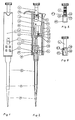
- a pipette according to Fig. 1 and 2 has a body 1 and at its lower end a cylinder part 2. At the upper end of the body there is a press knob 3. The upper part of the body forms a handle to be grasped with a palm grip.
- An exchangable liquid jet container 4 is fixed to the lower end of the cylinder part 2.
- a display 7 which indicates e.g. the volume set, and switches 8 by means of which e.g. the volume can be set.
- the cylinder part 2 has a piston 9 reciprocating in the cylinder (Fig. 2). Its rotational movement relative to the cylinder is prevented by means of guides 10.
- the piston 9 is moved by means of an electric motor 11.
- the motion of the motor is transmitted by means of a transmission mechanism formed from a coupling 12 and a gear-wheel system to a journalled guide screw 14.
- the coupling has a spring, which presses the gear wheel against an end flange of the shaft. In this way, the coupling slides at a certain boundary moment.
- a guide nut 15 corresponding to the guide screw, and a space inside the piston such that the piston can move over the guide screw. When the guide screw is rotated, the piston thus moves either upwardly or downwardly depending on the rotational direction.
- an accumulator 16 acts as the power source for the motor.
- the movement of the piston 9 is followed by a system 17, which has a rotating encoder disk 18 connected to the transmission system and a pair of sensors 19 counting its lines. By means of the system, it is possible to indicate both the location and the speed of the piston.
- the press knob 3 is fitted to be slidable in a longitudinal slot 20 of the body 1.
- the knob is connected with a primary spring 21, which presses the knob into an upper position.
- the knob is further connected with a secondary spring 22, which presses the knob upwards after the knob is pressed beneath the lower position.
- the knob is further connected with a primary coupling 23 and a secondary coupling 24 (Fig. 6-8), by means of which the functional step of the knob is identified.
- Fig. 3 and 4 show as examples different measurement methods.
- the system of Fig. 3 is based on a pulse sensor. It includes on the arm of the knob 3 encoder lines 26 and on the walls of the slot 20 fixed encoder lines 27. The lines 26 and 27 are read by means of an optic sensor 28.
- the system 25.2 of Fig. 4 is based on a resistance sensor. It includes a fixed resistor 29 fixed to the slot 20 and a fork 30 sliding on a resistor fixed to the arm of the knob 3.
- the resistance measured by the system is comparable to the piston displacement.
- Such a system is more advantageous from the point of view of the current consumption than systems based on optic sensors.
- a system based on an optic-analog sensor can also be used.
- the knob is positioned as an extension for the upper end of the body 1, to be used by the thumb in a similar manner than that utilized in pipettes operating by manual force.
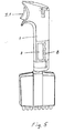
- Fig. 5 shows a multichannel pipette comprising eight cylinders. Otherwise the system corresponds to that of Fig. 1 and 2.
- Both the piston-movement monitoring system 17 and the press-knob-displacement measuring system 25 are connected to an electronic control system 33 (Fig. 2).
- the cylinder section 2 with its piston 9 may form a removable module.
- the cylinder section has a code 34 indicating the volume range, e.g. a code formed from bulges or slots, and in the body a code reader 35, e.g. a reader formed from switches, connected correspondingly to the control system 33.
- the code reader 35 can be based on the measurement of e.g. inductance, capacitance or resistance, too.
- Fig. 6-8 The operation of the pipette is illustrated by means of Fig. 6-8.
- the press knob 3 is in the upper position and the piston 9 in the upper position corresponding to the last pipetted volume.
- the volume is reset, and the knob is pressed into the lower position against the force of the primary spring 21.
- the measurement system 25 gives an information to the control system, by means of whose control the piston is driven to the lower position (Fig. 2).
- the jet container 4 of the pipette is now brought into the liquid and the knob is released into the upper position.
- the measurement system provides an information about the upward transfer of knob to the control system, and the piston is driven to an upper position corresponding to the set volume (Fig. 1).
- the knob is pressed past the lower position against the force of the secondary spring 22 into an discharge position.
- the measurement system provides an information thereof to the control system, which correspondingly performs the driving of the piston into the discharge position.
- the knob is released, the piston correspondingly returns into the upper position.
- the pipette can be used in a stepping mode, too, whereby a sucked-in amount of liquid is dosed out as smaller doses. In this case, one pressing of the knob to the lower position moves the piston one step downwards.
- the programmed controller circuit D1 performs all the operations related to the interface (display 7, keyboard 8, code keys 35) of the pipette, to the runs of the motor 11 (pipetting, stepping) and to the charging of the accumulators 16.
- the programs of the interface follow the commands to be given from the keyboard 8 and transmit the program execution according to them.
- the volume to be dosed in the pipetting mode is comparative with the position of the operating switch.
- the dosing of the volume selected in the stepping operation is started up by means of a primary movement of the operating switch.
- the loading operation starts up, when a switching of the loading voltage is observed in the inlet of the controller D1.
- the display LCD-1 and the keyboard S1...S4 are directly connected to the corresponding controllers of the controller circuit D1.
- a separate bridge comprised of channel transistors V1...V4, which bridge is controlled by the controller.
- auxiliary functions related to the controller are a buzzer H1 activated by malfunctions and an indication of the operative voltage.
- an inertia switch 36 connected to the controller D1. This reacts to the movement of the pipette and activates the controller. Correspondingly, the controller is deactivated when the pipette has stayed unmoved e.g. for five minutes.
- This system acts as an automatic power on/off switch. It helps to save the batteries and also facilitates the use of the pipette.
Landscapes
- Health & Medical Sciences (AREA)
- Clinical Laboratory Science (AREA)
- Chemical & Material Sciences (AREA)
- Chemical Kinetics & Catalysis (AREA)
- Sampling And Sample Adjustment (AREA)
- Devices For Use In Laboratory Experiments (AREA)
- Feeding, Discharge, Calcimining, Fusing, And Gas-Generation Devices (AREA)
- Materials For Medical Uses (AREA)
- Medicines Containing Antibodies Or Antigens For Use As Internal Diagnostic Agents (AREA)
Claims (10)
- Pipette, welche aufweist einen Körper und darin ein unteres Ende und ein oberes Ende, einen Zylinder, welcher von unten offen ist an dem unteren Ende des Körpers, darin einen Kolben (9), bewegbar zwischen der unteren und der oberen Position zum Aufsaugen von Flüssigkeit hinein in die Pipette und um sie daraus zu entfernen, einen Motor und einen Getriebemechanismus (12, 13), damit in Verbindung stehend zum Bewegen des Kolbens, ein Stoppsystem zum Stoppen der Kolbenbewegung in einer gewünschten Position, ein Kolbenbewegungsaufzeichnungssystem (17), und ein elektronisches Steuersystem (33) zum Steuern der Bewegung des Kolbens, welches auf der Basis der Information, welche bereitgestellt ist durch das Aufzeichnungssystem, einen Befehl für das Stoppsystem gibt, um die Kolbenbewegung zu stoppen,
dadurch gekennzeichnet, daß die Pipette umfaßt- einen Knopf (3), welcher gleitfähig hin- und herbewegbar in dem Körper angeordnet ist; zwischen einer unteren Position und einer oberen Position, wobei die untere und die obere Position des Knopfes der unteren und oberen Position des Kolbens entspricht,und- ein Knopfversetzungsmeßsystem (25), welches mit dem Steuersystem derart verbunden ist, daß die Knopfversetzung die Kolbenbewegung mittels des Steuersystemes steuert. - Pipette nach Anspruch 1,
dadurch gekennzeichnet, daß sie ein Stoppsystem umfaßt, welches vor dem Stoppen der Kolbenbewegung die Bewegungsgeschwindigkeit mittels des Motors verzögert. - Pipette nach Anspruch 2,
dadurch gekennzeichnet, daß sie ein Stoppsystem umfaßt, welches die Kolbengeschwindigkeit auf Null verzögert. - Pipette nach einem der Ansprüche 1 bis 3,
dadurch gekennzeichnet, daß sie einen Kolben (9) umfaßt, wovon eine Position, bevorzugt die obere Position, einstellbar ist. - Pipette nach einem der Ansprüche 1 bis 4,
dadurch gekennzeichnet, daß sie einen Zylinderteil (2) umfaßt, welcher austauschbar ist. - Pipette nach einem der Ansprüche 1 bis 5,
dadurch gekennzeichnet, daß sie einen Federmechanismus (21) umfaßt, um den Knopf in die obere Position zu drücken. - Pipette nach einem der Ansprüche 1 bis 6,
dadurch gekennzeichnet, daß sie einen Kolben (9) umfaßt, welcher zusätzlich bewegt werden kann unter die untere Position hinein in eine Ausstoßposition, sowie einen Knopf (3), welcher entsprechend bewegt werden kann in eine Ausstoßposition unter der unteren Position, und daß sie bevorzugt des weiteren einen Federmechanismus (22) umfaßt, welcher der Übertragung des Knopfes über die untere Position hinaus hin zu der Ausstoßposition widersteht. - Pipette nach einem der Ansprüche 1 bis 7, bei welcher der Körper einen Griff aufweist, welcher durch die Handfläche zu ergreifen ist,
dadurch gekennzeichnet, daß der Knopf (3) übertragen bzw. bewegt werden kann hin zu dem Körper und weg davon, bevorzugt seitwärtig zu dem Körper und seitwärtig weg davon. - Pipette nach einem der Ansprüche 1 bis 8,
dadurch gekennzeichnet, daß das Steuersystem mit einem Sensor (36) verbunden ist, und daß das Steuersystem automatisch aktiviert wird durch ein Signal, welches durch den Sensor bereitgestellt wird. - Verfahren zum Steuern der Bewegung eines Kolbens in einer Pipette nach Anspruch 1,
dadurch gekennzeichnet, daß die Kolbenbewegung gesteuert wird mittels eines Knopfes, welcher gleitfähig hin- und herbewegbar ist in dem Körper, so daß die Versetzung des Knopfes die Kolbenbewegung mittels eines Steuersystemes steuert.
Applications Claiming Priority (2)
| Application Number | Priority Date | Filing Date | Title |
|---|---|---|---|
| FI922939 | 1992-06-24 | ||
| FI922939A FI922939A0 (fi) | 1992-06-24 | 1992-06-24 | Knappipett. |
Publications (3)
| Publication Number | Publication Date |
|---|---|
| EP0576967A2 EP0576967A2 (de) | 1994-01-05 |
| EP0576967A3 EP0576967A3 (en) | 1994-05-25 |
| EP0576967B1 true EP0576967B1 (de) | 1997-09-10 |
Family
ID=8535526
Family Applications (1)
| Application Number | Title | Priority Date | Filing Date |
|---|---|---|---|
| EP93109949A Expired - Lifetime EP0576967B1 (de) | 1992-06-24 | 1993-06-22 | Motorisch angetriebene Pipette |
Country Status (7)
| Country | Link |
|---|---|
| US (1) | US5389341A (de) |
| EP (1) | EP0576967B1 (de) |
| JP (1) | JP3561746B2 (de) |
| AT (1) | ATE157910T1 (de) |
| AU (1) | AU662639B2 (de) |
| DE (1) | DE69313737T2 (de) |
| FI (2) | FI922939A0 (de) |
Cited By (1)
| Publication number | Priority date | Publication date | Assignee | Title |
|---|---|---|---|---|
| US7146867B2 (en) | 2003-01-16 | 2006-12-12 | Eppendorf Ag | Proportioning device |
Families Citing this family (53)
| Publication number | Priority date | Publication date | Assignee | Title |
|---|---|---|---|---|
| DE4341229C2 (de) * | 1993-12-03 | 1995-09-07 | Eppendorf Geraetebau Netheler | Pipettensystem |
| DE59509794D1 (de) | 1994-07-07 | 2001-12-13 | Brand Gmbh & Co Kg | Pipettiersystem |
| US6090348A (en) * | 1997-03-14 | 2000-07-18 | Becton, Dickinson And Company | Method for programming an electronic pipetter |
| US6253628B1 (en) | 1998-08-21 | 2001-07-03 | Becton Dickinson And Company | Apparatus for drawing liquids into and expelling liquids from a pipet at variable flow rates |
| WO2000051738A1 (en) * | 1999-03-05 | 2000-09-08 | Rainin Instrument Co., Inc. | Improved battery powered microprocessor controlled hand portable electronic pipette |
| US6254832B1 (en) * | 1999-03-05 | 2001-07-03 | Rainin Instrument Co., Inc. | Battery powered microprocessor controlled hand portable electronic pipette |
| US6299841B1 (en) * | 1999-03-05 | 2001-10-09 | Rainin Instrument Co., Inc. | Bilaterally symmetrical battery powered microprocessor controlled lightweight hand-holdable electronic pipette |
| DE19915066C2 (de) | 1999-04-01 | 2001-09-13 | Brand Gmbh & Co Kg | Verfahren zur Erkennung des Typs von austauschbaren gerätespezifischen Kolben-Zylinder-Einheiten für Pipettier- oder Dosiergeräte sowie Pipettier- und Dosiersystem |
| DE19915771C1 (de) * | 1999-04-08 | 2001-01-04 | Retec Elektronische Regeltechn | System zum Aufnehmen und Abgeben von Fluidvolumina |
| DE10001938C2 (de) * | 2000-01-19 | 2002-08-01 | Retec Elektronische Regeltechn | System zum Aufnehmen und Abgeben von Fluidvolumina und Verwendung des Systems |
| US6428750B1 (en) * | 2000-02-17 | 2002-08-06 | Rainin Instrument, Llc | Volume adjustable manual pipette with quick set volume adjustment |
| US6749812B2 (en) * | 2000-06-26 | 2004-06-15 | Vistalab Technologies | Automatic pipette detipping |
| US6601433B2 (en) | 2000-06-26 | 2003-08-05 | Vistalab Technologies, Inc. | Hand-held pipette |
| AU2001275197A1 (en) * | 2000-06-26 | 2002-01-08 | Vistalab Technologies, Inc. | Handheld pipette |
| US6861034B1 (en) * | 2000-11-22 | 2005-03-01 | Xerox Corporation | Priming mechanisms for drop ejection devices |
| JP4148894B2 (ja) * | 2001-10-16 | 2008-09-10 | マトリックス・テクノロジイズ・コーポレーション | 手持ち式ピペット |
| SG115456A1 (en) * | 2002-03-04 | 2005-10-28 | Micron Technology Inc | Semiconductor die packages with recessed interconnecting structures and methods for assembling the same |
| EP1531935A1 (de) * | 2002-08-27 | 2005-05-25 | PZ HTL Spolka Akcyjna | Verfahren zum eichen einer pipette |
| US20060027033A1 (en) * | 2002-10-16 | 2006-02-09 | Richard Cote | Hand-held pipette employing voice recognition control |
| US7284454B2 (en) * | 2004-05-27 | 2007-10-23 | Matrix Technologies Corporation | Hand held pipette |
| PL357692A1 (en) * | 2002-12-11 | 2004-06-14 | P.Z.HTL Spółka Akcyjna | Method of parameter readout of pipette exchangeable bars and the pipette featuring exchangeable bar parameter readout |
| US7093507B2 (en) * | 2003-05-12 | 2006-08-22 | Bel-Art Products, Inc. | Pipette control arrangement |
| US7396512B2 (en) * | 2003-11-04 | 2008-07-08 | Drummond Scientific Company | Automatic precision non-contact open-loop fluid dispensing |
| USD510629S1 (en) | 2004-01-16 | 2005-10-11 | Heathrow Scientific Llc | Pipette device with pivotable nozzle assembly |
| US7381371B2 (en) * | 2004-01-16 | 2008-06-03 | Heathrow Scientific Llc | Pipette device with pivotable nozzle assembly |
| US7875463B2 (en) * | 2004-03-26 | 2011-01-25 | Agilent Technologies, Inc. | Generalized pulse jet ejection head control model |
| DE102004022419B4 (de) * | 2004-05-06 | 2007-01-25 | Eppendorf Ag | Pipette |
| FI116612B (fi) * | 2004-07-05 | 2006-01-13 | Biohit Oyj | Imulaite |
| US20060085162A1 (en) * | 2004-10-15 | 2006-04-20 | Bjornson Torleif O | Laboratory sample transfer apparatus with interchangeable tools |
| DE102005033378B4 (de) * | 2005-07-16 | 2012-05-31 | Eppendorf Ag | Kolbenhubpipette |
| DE102006009816A1 (de) | 2006-02-28 | 2007-09-06 | Eppendorf Ag | System und Verfahren zum Titrieren von Flüssigkeiten |
| TW200809202A (en) * | 2006-08-04 | 2008-02-16 | Arise Biotech Corp | Electric micro-quantum injector capable of a real time reaction for push-action of the arms |
| DE102006037213A1 (de) * | 2006-08-09 | 2008-02-14 | Eppendorf Ag | Elektronische Dosiervorrichtung zum Dosieren von Flüssigkeiten |
| US20090007701A1 (en) * | 2007-07-03 | 2009-01-08 | Hadjis Peter T | Pivoting pipette device |
| US20090010809A1 (en) * | 2007-07-03 | 2009-01-08 | Hadjis Peter T | Manual pipette filler |
| DE102007042555A1 (de) * | 2007-09-07 | 2009-04-02 | Eppendorf Ag | Pipette mit Kolben-Positionsanzeige |
| USD591865S1 (en) * | 2007-10-22 | 2009-05-05 | Biohit Oyj | Pipette |
| USD592314S1 (en) * | 2007-11-27 | 2009-05-12 | Dragon Medical (Shanghai) Limited | Pipette |
| USD620602S1 (en) | 2008-01-03 | 2010-07-27 | Vistalab Technologies, Inc. | Pipette |
| DE102012016020A1 (de) | 2012-08-13 | 2014-02-13 | Eppendorf Ag | Pipettiervorrichtung, Pipettierbehälter und Verfahren zu dessen Herstellung |
| EP2826722B1 (de) * | 2013-07-19 | 2016-06-29 | Mettler-Toledo GmbH | Handdosiergerät und Verfahren zum Dosieren von pulver- oder pastenförmigem Dosiergut |
| FI125449B (en) | 2013-12-18 | 2015-10-15 | Thermo Fisher Scientific Oy | Electronic pipette |
| USD772426S1 (en) * | 2014-01-13 | 2016-11-22 | Gilson, Inc. | Pipette system cartridge |
| USD798469S1 (en) * | 2014-06-26 | 2017-09-26 | Gilson Sas | Pipette |
| DE202017101008U1 (de) | 2017-02-23 | 2018-05-24 | Brand Gmbh + Co Kg | Dispenser und System zum Aufnehmen und Abgeben von Fluidvolumina |
| CN107597222B (zh) * | 2017-09-08 | 2019-09-27 | 莫纳(苏州)生物科技有限公司 | 电动手工加样器 |
| CN113828368B (zh) * | 2020-06-23 | 2025-09-30 | 梅特勒-托利多仪器(上海)有限公司 | 低功耗电动移液器 |
| CN113231117B (zh) * | 2021-06-02 | 2025-02-11 | 莫纳(苏州)生物科技有限公司 | 一种加样信息可追溯的电动手工加样枪及加样装置 |
| JP1735107S (ja) * | 2022-02-23 | 2023-01-20 | ペット用投薬器 | |
| FR3134521A1 (fr) * | 2022-04-14 | 2023-10-20 | Apollina | Dispositif de motorisation des mouvements du piston d’un réservoir de fluide utilisé dans le milieu médical |
| US20230330322A1 (en) * | 2022-04-14 | 2023-10-19 | Apollina | Device for motorizing the movements of the piston of a fluid tank used in the medical environment |
| USD982855S1 (en) * | 2022-08-19 | 2023-04-04 | Jinhua Jiu Miao Enterprise Management Co., Ltd. | Medicine syringe for a pet |
| CN120112361A (zh) | 2022-10-27 | 2025-06-06 | 因特格拉生物科学股份公司 | 吸移管装置 |
Family Cites Families (11)
| Publication number | Priority date | Publication date | Assignee | Title |
|---|---|---|---|---|
| FI46688C (fi) * | 1971-06-23 | 1973-06-11 | Suovaniemi | Pipetti |
| FI55093C (fi) * | 1974-07-05 | 1979-05-10 | Osmo Antero Suovaniemi | Foerfarande foer exakt maetning av absorption av smao vaetskemaengder samt anordning foer dess genomfoerande |
| US4399711A (en) * | 1980-04-18 | 1983-08-23 | Beckman Instruments, Inc. | Method and apparatus ensuring full volume pickup in an automated pipette |
| JPS5919736B2 (ja) * | 1981-02-09 | 1984-05-08 | 株式会社ニチリヨ− | ピペット装置 |
| US4519258A (en) * | 1983-10-11 | 1985-05-28 | Eastman Kodak Company | Motorized pipette |
| US4671123A (en) * | 1984-02-16 | 1987-06-09 | Rainin Instrument Co., Inc. | Methods and apparatus for pipetting and/or titrating liquids using a hand held self-contained automated pipette |
| FI852704L (fi) * | 1985-07-08 | 1987-01-09 | Labsystems Oy | Eldriven pipett. |
| US4821586A (en) * | 1988-02-25 | 1989-04-18 | Medical Laboratory Automation, Inc. | Programmable pipette |
| US4944481A (en) * | 1988-06-30 | 1990-07-31 | Next, Inc. | Balanced monitor stand |
| US4988481A (en) * | 1989-01-30 | 1991-01-29 | Labsystems Oy | Electrical pipette |
| FI87740C (fi) * | 1990-05-04 | 1994-04-08 | Biohit Oy | Pipett |
-
1992
- 1992-06-24 FI FI922939A patent/FI922939A0/fi not_active Application Discontinuation
-
1993
- 1993-06-22 US US08/079,776 patent/US5389341A/en not_active Expired - Lifetime
- 1993-06-22 AT AT93109949T patent/ATE157910T1/de not_active IP Right Cessation
- 1993-06-22 EP EP93109949A patent/EP0576967B1/de not_active Expired - Lifetime
- 1993-06-22 DE DE69313737T patent/DE69313737T2/de not_active Expired - Lifetime
- 1993-06-24 FI FI932942A patent/FI96007C/fi not_active IP Right Cessation
- 1993-06-24 AU AU41483/93A patent/AU662639B2/en not_active Ceased
- 1993-06-24 JP JP17730493A patent/JP3561746B2/ja not_active Expired - Fee Related
Cited By (1)
| Publication number | Priority date | Publication date | Assignee | Title |
|---|---|---|---|---|
| US7146867B2 (en) | 2003-01-16 | 2006-12-12 | Eppendorf Ag | Proportioning device |
Also Published As
| Publication number | Publication date |
|---|---|
| EP0576967A2 (de) | 1994-01-05 |
| EP0576967A3 (en) | 1994-05-25 |
| US5389341A (en) | 1995-02-14 |
| ATE157910T1 (de) | 1997-09-15 |
| AU4148393A (en) | 1994-01-06 |
| AU662639B2 (en) | 1995-09-07 |
| FI932942L (fi) | 1993-12-25 |
| FI932942A0 (fi) | 1993-06-24 |
| DE69313737T2 (de) | 1998-03-26 |
| JP3561746B2 (ja) | 2004-09-02 |
| DE69313737D1 (de) | 1997-10-16 |
| FI96007B (fi) | 1996-01-15 |
| FI96007C (fi) | 1996-04-25 |
| FI922939A0 (fi) | 1992-06-24 |
| JPH08187438A (ja) | 1996-07-23 |
Similar Documents
| Publication | Publication Date | Title |
|---|---|---|
| US5389341A (en) | Knob pipette | |
| US4475666A (en) | Automated liquid dispenser control | |
| EP1438138B1 (de) | Hand-pipettiervorrichtung | |
| US7421913B2 (en) | Pipette | |
| US4821586A (en) | Programmable pipette | |
| US6352673B1 (en) | Ergonomic return springless manual air displacement pipette | |
| JPH02290260A (ja) | 電気ピペット | |
| US10105698B2 (en) | Pipette with a tracking system | |
| EP1750842B1 (de) | Handpipette | |
| EP3083058B1 (de) | Elektronische pipette | |
| JP7361621B2 (ja) | 自動ピペットモジュールにおけるチップの取り外し | |
| EP1305114B1 (de) | Pipette mit mechanischen mitteln zum lokalisieren und anhalten der ruhestellung | |
| US7146867B2 (en) | Proportioning device | |
| EP1296761A2 (de) | Verbesserte handgehaltene pipette | |
| US20110214518A1 (en) | Electronic piston stroke pipette | |
| WO2004020096A1 (en) | Method of pipette calibration | |
| US20210001326A1 (en) | Method for Dosing Liquid by Means of a Pipette and a Syringe, and Pipette for Actuating a Syringe for Dosing Liquid | |
| EP0070571A2 (de) | Steuerung für automatisierte Flüssigkeitsabgabeeinrichtung | |
| JPH0457378B2 (de) | ||
| EP0695220B1 (de) | Kolbenhubpipette | |
| FI3892377T3 (fi) | Annostelija ja järjestelmä nestemäärien ottamiseksi ja annostelemiseksi | |
| CN120112361A (zh) | 吸移管装置 |
Legal Events
| Date | Code | Title | Description |
|---|---|---|---|
| PUAI | Public reference made under article 153(3) epc to a published international application that has entered the european phase |
Free format text: ORIGINAL CODE: 0009012 |
|
| AK | Designated contracting states |
Kind code of ref document: A2 Designated state(s): AT BE CH DE DK ES FR GB GR IT LI LU NL SE |
|
| PUAL | Search report despatched |
Free format text: ORIGINAL CODE: 0009013 |
|
| AK | Designated contracting states |
Kind code of ref document: A3 Designated state(s): AT BE CH DE DK ES FR GB GR IT LI LU NL SE |
|
| 17P | Request for examination filed |
Effective date: 19940928 |
|
| 17Q | First examination report despatched |
Effective date: 19950627 |
|
| GRAG | Despatch of communication of intention to grant |
Free format text: ORIGINAL CODE: EPIDOS AGRA |
|
| GRAH | Despatch of communication of intention to grant a patent |
Free format text: ORIGINAL CODE: EPIDOS IGRA |
|
| GRAH | Despatch of communication of intention to grant a patent |
Free format text: ORIGINAL CODE: EPIDOS IGRA |
|
| GRAA | (expected) grant |
Free format text: ORIGINAL CODE: 0009210 |
|
| AK | Designated contracting states |
Kind code of ref document: B1 Designated state(s): AT BE CH DE DK ES FR GB GR IT LI LU NL SE |
|
| PG25 | Lapsed in a contracting state [announced via postgrant information from national office to epo] |
Ref country code: NL Free format text: LAPSE BECAUSE OF FAILURE TO SUBMIT A TRANSLATION OF THE DESCRIPTION OR TO PAY THE FEE WITHIN THE PRESCRIBED TIME-LIMIT Effective date: 19970910 Ref country code: LI Free format text: LAPSE BECAUSE OF FAILURE TO SUBMIT A TRANSLATION OF THE DESCRIPTION OR TO PAY THE FEE WITHIN THE PRESCRIBED TIME-LIMIT Effective date: 19970910 Ref country code: IT Free format text: LAPSE BECAUSE OF FAILURE TO SUBMIT A TRANSLATION OF THE DESCRIPTION OR TO PAY THE FEE WITHIN THE PRE;WARNING: LAPSES OF ITALIAN PATENTS WITH EFFECTIVE DATE BEFORE 2007 MAY HAVE OCCURRED AT ANY TIME BEFORE 2007. THE CORRECT EFFECTIVE DATE MAY BE DIFFERENT FROM THE ONE RECORDED.SCRIBED TIME-LIMIT Effective date: 19970910 Ref country code: GR Free format text: LAPSE BECAUSE OF FAILURE TO SUBMIT A TRANSLATION OF THE DESCRIPTION OR TO PAY THE FEE WITHIN THE PRESCRIBED TIME-LIMIT Effective date: 19970910 Ref country code: ES Free format text: THE PATENT HAS BEEN ANNULLED BY A DECISION OF A NATIONAL AUTHORITY Effective date: 19970910 Ref country code: DK Free format text: LAPSE BECAUSE OF NON-PAYMENT OF DUE FEES Effective date: 19970910 Ref country code: CH Free format text: LAPSE BECAUSE OF FAILURE TO SUBMIT A TRANSLATION OF THE DESCRIPTION OR TO PAY THE FEE WITHIN THE PRESCRIBED TIME-LIMIT Effective date: 19970910 Ref country code: BE Effective date: 19970910 Ref country code: AT Effective date: 19970910 |
|
| REF | Corresponds to: |
Ref document number: 157910 Country of ref document: AT Date of ref document: 19970915 Kind code of ref document: T |
|
| REG | Reference to a national code |
Ref country code: CH Ref legal event code: EP |
|
| REF | Corresponds to: |
Ref document number: 69313737 Country of ref document: DE Date of ref document: 19971016 |
|
| ET | Fr: translation filed | ||
| NLV1 | Nl: lapsed or annulled due to failure to fulfill the requirements of art. 29p and 29m of the patents act | ||
| REG | Reference to a national code |
Ref country code: CH Ref legal event code: PL |
|
| PG25 | Lapsed in a contracting state [announced via postgrant information from national office to epo] |
Ref country code: LU Free format text: LAPSE BECAUSE OF NON-PAYMENT OF DUE FEES Effective date: 19980622 |
|
| PLBE | No opposition filed within time limit |
Free format text: ORIGINAL CODE: 0009261 |
|
| STAA | Information on the status of an ep patent application or granted ep patent |
Free format text: STATUS: NO OPPOSITION FILED WITHIN TIME LIMIT |
|
| 26N | No opposition filed | ||
| REG | Reference to a national code |
Ref country code: GB Ref legal event code: IF02 |
|
| PGFP | Annual fee paid to national office [announced via postgrant information from national office to epo] |
Ref country code: SE Payment date: 20090625 Year of fee payment: 17 |
|
| EUG | Se: european patent has lapsed | ||
| PGFP | Annual fee paid to national office [announced via postgrant information from national office to epo] |
Ref country code: GB Payment date: 20110622 Year of fee payment: 19 |
|
| PGFP | Annual fee paid to national office [announced via postgrant information from national office to epo] |
Ref country code: FR Payment date: 20110722 Year of fee payment: 19 |
|
| PGFP | Annual fee paid to national office [announced via postgrant information from national office to epo] |
Ref country code: DE Payment date: 20110621 Year of fee payment: 19 |
|
| PG25 | Lapsed in a contracting state [announced via postgrant information from national office to epo] |
Ref country code: SE Free format text: LAPSE BECAUSE OF NON-PAYMENT OF DUE FEES Effective date: 20100623 |
|
| GBPC | Gb: european patent ceased through non-payment of renewal fee |
Effective date: 20120622 |
|
| REG | Reference to a national code |
Ref country code: FR Ref legal event code: ST Effective date: 20130228 |
|
| REG | Reference to a national code |
Ref country code: DE Ref legal event code: R119 Ref document number: 69313737 Country of ref document: DE Effective date: 20130101 |
|
| PG25 | Lapsed in a contracting state [announced via postgrant information from national office to epo] |
Ref country code: FR Free format text: LAPSE BECAUSE OF NON-PAYMENT OF DUE FEES Effective date: 20120702 Ref country code: GB Free format text: LAPSE BECAUSE OF NON-PAYMENT OF DUE FEES Effective date: 20120622 Ref country code: DE Free format text: LAPSE BECAUSE OF NON-PAYMENT OF DUE FEES Effective date: 20130101 |