EP0576859B1 - Turbo machine with axial dry gas seal - Google Patents
Turbo machine with axial dry gas seal Download PDFInfo
- Publication number
- EP0576859B1 EP0576859B1 EP93108994A EP93108994A EP0576859B1 EP 0576859 B1 EP0576859 B1 EP 0576859B1 EP 93108994 A EP93108994 A EP 93108994A EP 93108994 A EP93108994 A EP 93108994A EP 0576859 B1 EP0576859 B1 EP 0576859B1
- Authority
- EP
- European Patent Office
- Prior art keywords
- pressure
- machine
- seal
- turbo
- leakage
- Prior art date
- Legal status (The legal status is an assumption and is not a legal conclusion. Google has not performed a legal analysis and makes no representation as to the accuracy of the status listed.)
- Revoked
Links
Images
Classifications
-
- F—MECHANICAL ENGINEERING; LIGHTING; HEATING; WEAPONS; BLASTING
- F16—ENGINEERING ELEMENTS AND UNITS; GENERAL MEASURES FOR PRODUCING AND MAINTAINING EFFECTIVE FUNCTIONING OF MACHINES OR INSTALLATIONS; THERMAL INSULATION IN GENERAL
- F16J—PISTONS; CYLINDERS; SEALINGS
- F16J15/00—Sealings
- F16J15/16—Sealings between relatively-moving surfaces
- F16J15/34—Sealings between relatively-moving surfaces with slip-ring pressed against a more or less radial face on one member
- F16J15/3492—Sealings between relatively-moving surfaces with slip-ring pressed against a more or less radial face on one member with monitoring or measuring means associated with the seal
-
- F—MECHANICAL ENGINEERING; LIGHTING; HEATING; WEAPONS; BLASTING
- F01—MACHINES OR ENGINES IN GENERAL; ENGINE PLANTS IN GENERAL; STEAM ENGINES
- F01D—NON-POSITIVE DISPLACEMENT MACHINES OR ENGINES, e.g. STEAM TURBINES
- F01D11/00—Preventing or minimising internal leakage of working-fluid, e.g. between stages
- F01D11/02—Preventing or minimising internal leakage of working-fluid, e.g. between stages by non-contact sealings, e.g. of labyrinth type
- F01D11/04—Preventing or minimising internal leakage of working-fluid, e.g. between stages by non-contact sealings, e.g. of labyrinth type using sealing fluid, e.g. steam
- F01D11/06—Control thereof
-
- F—MECHANICAL ENGINEERING; LIGHTING; HEATING; WEAPONS; BLASTING
- F01—MACHINES OR ENGINES IN GENERAL; ENGINE PLANTS IN GENERAL; STEAM ENGINES
- F01D—NON-POSITIVE DISPLACEMENT MACHINES OR ENGINES, e.g. STEAM TURBINES
- F01D21/00—Shutting-down of machines or engines, e.g. in emergency; Regulating, controlling, or safety means not otherwise provided for
- F01D21/14—Shutting-down of machines or engines, e.g. in emergency; Regulating, controlling, or safety means not otherwise provided for responsive to other specific conditions
-
- F—MECHANICAL ENGINEERING; LIGHTING; HEATING; WEAPONS; BLASTING
- F04—POSITIVE - DISPLACEMENT MACHINES FOR LIQUIDS; PUMPS FOR LIQUIDS OR ELASTIC FLUIDS
- F04D—NON-POSITIVE-DISPLACEMENT PUMPS
- F04D27/00—Control, e.g. regulation, of pumps, pumping installations or pumping systems specially adapted for elastic fluids
- F04D27/02—Surge control
- F04D27/0292—Stop safety or alarm devices, e.g. stop-and-go control; Disposition of check-valves
-
- F—MECHANICAL ENGINEERING; LIGHTING; HEATING; WEAPONS; BLASTING
- F04—POSITIVE - DISPLACEMENT MACHINES FOR LIQUIDS; PUMPS FOR LIQUIDS OR ELASTIC FLUIDS
- F04D—NON-POSITIVE-DISPLACEMENT PUMPS
- F04D29/00—Details, component parts, or accessories
- F04D29/08—Sealings
- F04D29/10—Shaft sealings
- F04D29/12—Shaft sealings using sealing-rings
- F04D29/122—Shaft sealings using sealing-rings especially adapted for elastic fluid pumps
- F04D29/124—Shaft sealings using sealing-rings especially adapted for elastic fluid pumps with special means for adducting cooling or sealing fluid
-
- F—MECHANICAL ENGINEERING; LIGHTING; HEATING; WEAPONS; BLASTING
- F16—ENGINEERING ELEMENTS AND UNITS; GENERAL MEASURES FOR PRODUCING AND MAINTAINING EFFECTIVE FUNCTIONING OF MACHINES OR INSTALLATIONS; THERMAL INSULATION IN GENERAL
- F16J—PISTONS; CYLINDERS; SEALINGS
- F16J15/00—Sealings
- F16J15/16—Sealings between relatively-moving surfaces
- F16J15/34—Sealings between relatively-moving surfaces with slip-ring pressed against a more or less radial face on one member
- F16J15/3404—Sealings between relatively-moving surfaces with slip-ring pressed against a more or less radial face on one member and characterised by parts or details relating to lubrication, cooling or venting of the seal
Landscapes
- Engineering & Computer Science (AREA)
- General Engineering & Computer Science (AREA)
- Mechanical Engineering (AREA)
- Turbine Rotor Nozzle Sealing (AREA)
- Sealing Using Fluids, Sealing Without Contact, And Removal Of Oil (AREA)
- Structures Of Non-Positive Displacement Pumps (AREA)
Description
Die Erfindung betrifft eine Turbomaschine mit einer wenigstens an einer Seite der durch das Maschinengehäuse geführten Rotorwelle vorgesehenen axialen Dichtungsanordnung mit wenigstens einer gegen höheren Innendruck dichtenden Trockengasgleitringdichtung, welche mit Sperrgas beaufschlagt ist, und dessen Leckage über eine Leckageleitung abführbar ist.The invention relates to a turbomachine having an axial sealing arrangement provided at least on one side of the rotor shaft guided through the machine housing and having at least one dry gas sliding ring seal which seals against higher internal pressure and which is acted on by sealing gas and the leakage of which can be discharged via a leakage line.
Maschinen dieser Art sind beispielsweise aus DE 39 25 403 bekannt und dienen beispielsweise als Turbokompressoren oder Gasturbinen. Dabei ist der Rotor der Turbomaschine in einem geschlossenen Gehäuse angeordnet, dessen Innenraum unter höherem Gasdruck steht. Die Durchführung der Rotorwelle durch das Gehäuse nach aussen oder zu einer Zwischenkammer ist mittels einer Dichtungsanordnung abgedichtet, um ein Ausströmen des Druckgases aus dem Innenraum zu verhindern. In der Regel ist dabei bei an beiden Seiten des Rotors durch das Gehäuse geführten Wellen auch an beiden Seiten eine derartige Dichtungsanordnung vorgesehen, oder bei nur einseitig vorgesehenen Wellendurchführungen bei Maschinen vom Ueberhangtyp nur an dieser einen Wellendurchführung.Machines of this type are known for example from DE 39 25 403 and serve, for example, as turbo compressors or gas turbines. The rotor of the turbomachine is arranged in a closed housing, the interior of which is under higher gas pressure. The passage of the rotor shaft through the housing to the outside or to an intermediate chamber is by means of a Sealed arrangement sealed to prevent the compressed gas from flowing out of the interior. As a rule, in the case of shafts guided through the housing on both sides of the rotor, such a sealing arrangement is also provided on both sides, or, in the case of shaft bushings provided only on one side in machines of the overhang type, only on this one shaft bushing.
Als besonders reibungs- und verlustarm haben sich hierfür Trockengasdichtungen erwiesen, die mit einem Sperrgas beaufschlagt sind, wobei die Gleitfläche eines Gleitringes an eine entsprechende Dichtfläche gedrückt wird, unter Beibehaltung eines minimalen Spaltes, und somit den Austritt des Druckgases aus dem Innenraum minimalisiert, wobei die Leckage der Dichtung auf einem kleinstmöglichen Wert gehalten und gleichzeitig ein Spalt zum berührungslosen Lauf der Dichtung gebildet wird. Die geringe trotzdem noch vorhandene Leckage wird dabei in der Regel nach aussen abgeführt. Bei geringeren Drücken genügt in der Regel eine einzige Trockengasdichtung. Bei höheren Drücken ist jedoch zur Erzielung einer grösseren Sicherung der primären inneren Trockengasdichtung eine sekundäre analog aufgebaute äussere Trockengasdichtung nachgeschaltet, welche den inneren Leckageraum gegen aussen abdichtet. Diese äussere Trockengasdichtung tritt dabei vorzugsweise nur dann in Aktion und wird wirksam, wenn die primäre Leckage zu gross wird, insbesondere bei einem Defekt der vorgeschalteten Trockengasdichtung. Nötigenfalls können auch mehr als zwei Trockengasdichtungen hintereinander geschaltet sein.For this purpose, dry gas seals which have been subjected to a sealing gas have proven to be particularly low-friction and low-loss, the sliding surface of a sliding ring being pressed against a corresponding sealing surface while maintaining a minimal gap, and thus minimizing the discharge of the compressed gas from the interior, the Leakage of the seal is kept to the lowest possible value and at the same time a gap is formed for contactless running of the seal. The small leakage that is still present is usually discharged to the outside. At lower pressures, a single dry gas seal is usually sufficient. At higher pressures, however, a secondary, similarly constructed outer dry gas seal, which seals the inner leakage space from the outside, is connected downstream in order to achieve greater security of the primary inner dry gas seal. This outer dry gas seal preferably only comes into action and becomes effective if the primary leakage becomes too large, in particular if the upstream dry gas seal is defective. If necessary, more than two dry gas seals can also be connected in series.
Bei Turbomaschinen, welche gefährliche, insbesondere explosive oder toxische Gase verarbeiten, ist es besonders wichtig und dringend erforderlich, den Austritt des gefährlichen, unter Druck stehenden Gases aus dem Gehäuseinnenraum zu verhindern oder auf ein ungefährliches Mass zu reduzieren, um eine Katastrophe zu vermeiden. Dazu werden an den gefährdeten Stellen der Maschine, beispielsweise in der Nähe der Gasdurchführungen geeignete Gassensoren vorgesehen, welche mit Vorteil eine spezifische Detektionsempfindlichkeit für das nachzuweisende Gas aufweisen, und welche bei Ueberschreitung einer bestimmten Gaskonzentration ein Warn- oder Alarmsignal auslösen oder geeignete Bekämpfungsmassnahmen in Gang setzen. Dies erfordert jedoch eine zusätzliche komplizierte Einrichtung, welche zudem erst dann reagieren kann, wenn bereits eine zur Signalauslösung genügende Gasmenge aus dem Gehäuse ausgetreten ist. Die dadurch bedingte Zeitverzögerung reicht häufig nicht aus, um eine Katastrophe vollständig zu verhindern.In turbomachinery that process dangerous, especially explosive or toxic gases, it is particularly important and urgent to prevent the dangerous, pressurized gas from escaping from the interior of the housing or to reduce it to a safe level in order to avoid a catastrophe. For this purpose, suitable gas sensors are provided at the vulnerable points of the machine, for example in the vicinity of the gas feedthroughs, which advantageously have a specific detection sensitivity for the gas to be detected and which trigger a warning or alarm signal when a certain gas concentration is exceeded or initiate suitable control measures . However, this requires an additional complicated device, which moreover can only react when a sufficient amount of gas has already escaped from the housing to trigger the signal. The resulting time delay is often not sufficient to completely prevent a disaster.
Eine weitere Möglichkeit zur Ueberwachung einer doppelten Gleitringdichtung in Tandemanordnung für Flüssigkeiten wird in der GB-A-2 204 366 gezeigt. An den Zwischenraum zwischen der inneren und äusseren Gleitringdichtung ist eine Leitung angeschlossen, welche zunächst in einem Umschaltventil endet, um nacheinander verschiedene Funktionen erfüllen zu können. In einer ersten Betriebsstellung ist das Umschaltventil geschlossen und ermöglicht bei unzulässigem Druckanstieg die Auslösung eines Alarms. Ein solcher Alarm wird ausgelöst, wenn die innere Gleitringdichtung defekt ist und die äussere Gleitringdichtung noch funktionstüchtig ist. Der Alarm wird nicht ausgelöst, wenn die äussere Gleitringdichtung beim Versagen der inneren Gleitringdichtung schon defekt ist. Aus diesem Grund muss die Funktionstüchtigkeit der äusseren Gleitringdichtung immer wieder überprüft werden, indem man über das Umschaltventil den Zwischenraum zwischen den Gleitringdichtungen in willkürlich zu wählenden Abständen mit einem Hilfsdrucksystem verbindet, um die Dichtheit der äusseren Gleitringdichtung mittels Druckablesung zu überprüfen. Man ist also nie ganz sicher, ob der Alarm im Bedarfsfall auch wirklich ausgelöst wird, da er von der Funktionstüchtigkeit einer weiteren Gleitringdichtung abhängt, deren Funktionieren theoretisch ständig überprüft werden müsste und die aus einem verschleissbehafteten Element mit elastischen Dichtungen besteht.Another possibility for monitoring a double mechanical seal in a tandem arrangement for liquids is shown in GB-A-2 204 366. A line is connected to the space between the inner and outer mechanical seal, which first ends in a changeover valve in order to be able to perform different functions one after the other. In a first operating position, the changeover valve is closed and enables an alarm to be triggered if the pressure rises excessively. Such an alarm is triggered when the inner mechanical seal is defective and the outer mechanical seal is still functional. The alarm is not triggered if the outer mechanical seal is defective when the inner mechanical seal fails. For this reason, the functionality of the outer mechanical seal must be checked again and again by connecting the space between the mechanical seals to an auxiliary pressure system at random intervals using the changeover valve in order to check the tightness of the outer mechanical seal by means of pressure reading. It is therefore never entirely certain whether the alarm will actually be triggered if necessary, since it depends on the functionality of another mechanical seal, the functioning of which would theoretically have to be constantly checked and which consists of a wear-prone element with elastic seals.
Die Erfindung setzt sich die Aufgabe, die oben aufgeführten Nachteile des Standes der Technik zu vermeiden und insbesondere eine Turbomaschine der eingangs angegebenen Art derart weiterzubilden, dass ein Defekt der Trockengasdichtung und ein unzulässiger Gasaustritt durch die Wellendichtungen schnellstmöglich und ohne Zeitverzögerung mit grösserer Sicherheit signalisiert und verhindert wird.The object of the invention is to avoid the disadvantages of the prior art listed above and, in particular, to further develop a turbomachine of the type specified at the outset in such a way that a defect in the dry gas seal and an inadmissible gas leakage through the shaft seals are signaled and prevented as quickly as possible and with no delay with greater certainty becomes.
Erfindungsgemäss wird diese Aufgabe mit den Merkmalen vom Anspruch 1 gelöst.According to the invention, this object is achieved with the features of
Mit Vorteil wird das Drucksignal dazu benützt, die Turbomaschine unverzüglich abzuschalten, um den Gasdruck im Innenraum abzusenken und einen Gasaustritt ohne Zeitverzögerung zu verhindern.The pressure signal is advantageously used to switch off the turbomachine immediately in order to lower the gas pressure in the interior and to prevent gas leakage without a time delay.
Bei der Ausbildung als Tandem- oder Mehrfachdichtung ist es von Vorteil, auch den inneren Leckagedruck zu überwachen und die Ueberschreitung eines Schwellenwertes zu signalisieren, beispielsweise durch ein Warn- oder Alarmsignal, während bei einem Anstieg des äusseren Leckagedruckes die Turbomaschine unverzüglich automatisch abgeschaltet wird.When designing as a tandem or multiple seal, it is advantageous to also monitor the internal leakage pressure and to signal when a threshold value has been exceeded, for example by means of a warning or alarm signal, while the turbomachine is automatically switched off immediately if the external leakage pressure rises.
Die Erfindung wird anhand der in den Figuren dargestellten Ausführungsbeispiele näher erläutert.
- Fig. 1
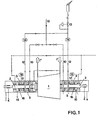
- zeigt eine Turbomaschinenanlage mit Trockengasdichtungen in schematischer Form;
- Fig. 2
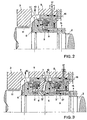
- zeigt einen Detailausschnitt einer einfachen Trockengasdichtungsanordnung einer Wellendurchführung zur Verwendung in der in Fig. 1 dargestellten Turbomaschinenanlage;
- Fig. 3
- zeigt einen Detailausschnitt einer Tandem-Trockengasdichtung für die gleiche Verwendung.
- Fig. 1
- shows a turbomachine system with dry gas seals in schematic form;
- Fig. 2
- shows a detail of a simple dry gas sealing arrangement of a shaft bushing for use in the turbomachine system shown in Fig. 1;
- Fig. 3
- shows a detail of a tandem dry gas seal for the same use.
Bei dem in den Figuren dargestellten Beispiel einer Turbomaschinenanlage mit einem Turbokompressor 1 ist die Rotorwelle 2 durch das nur im Durchführungsteil im Detail wiedergegebene Turbomaschinengehäuse 3 beidseits hindurchgeführt und in geeigneter Weise, beispielsweise in Magnetlagern 4 gelagert. Gegen das Gehäuse 3 ist die Welle 2 mittels Trockengasdichtungen 5 abgedichtet, welche den Gasaustritt aus dem Inneren der Turbomaschine 1 sowohl an der Gaseintrittsseite 1' als auch an der Austrittsseite 1'' bis auf eine unschädliche Leckage verhindern. Somit wird vermieden, dass das in der Maschine unter einem gewissen Druck stehende Gas in die Umgebung gelangt, und insbesondere im Falle eines toxischen oder explosiven Druckgases eine gefährliche Situation hervorrufen kann.In the example of a turbomachine system with a
Die Dichtungsanordnung 5 weist, wie insbesondere aus Fig. 2 ersichtlich ist, eine mitrotierende Wellenbüchse 6 auf, die einen Dichtkörper 7 trägt, beispielsweise aus Siliziumkarbid oder einem anderen geeigneten Material. Auf der Gegenseite weist die Dichtung einen in das Gehäuse 3 eingelassenen stationären Dichtungshalter 8 auf, der an seiner Innenseite einen axial etwas verschiebbaren Gleitring 9 trägt, beispielsweise mit einer Gleitfläche aus einem kohlekeramischen Werkstoff.As can be seen in particular from FIG. 2, the
Ueber eine Leitung 10 wird der inneren Trockengasdichtung 5 ein trockenes und sauberes Sperrgas mit einem gewissen Druck, der höher ist als der Druck im Gehäuseinneren zugeführt. Dieses Sperrgas blockiert dadurch einerseits den Austritt des Druckgases aus dem Gehäuseinneren, wobei eine weitere Dichtung 11, die als Labyrinthdichtung oder als weitere Trockengasdichtung ausgebildet sein kann, an der Innenseite der Wellendurchführung vorgesehen ist. Weiterhin gelangt das Sperrgas auf die Rückseite des stationären Gleitringes 9 und drückt diesen, gegebenenfalls unterstützt durch Federkraft, gegen den rotierenden Dichtkörper 7 an der Wellenbüchse 6, so dass zwischen Gleitring und Dichtkörper ein Gasfilm mit einem minimalen Spalt gebildet wird. Die durch die Trockengasdichtung 5 bzw. den Dichtspalt doch noch hindurchtretende Leckage wird über die Leckageleitung 17 auf unschädliche Weise abgeführt, beispielsweise aufgefangen oder abgefackelt. In der Leckageleitung 17 ist weiter eine Stauvorrichtung in der Form einer die Welle 2 umschliessenden, ringförmigen Stauscheibe 16 vorgesehen sowie eine Messeinrichtung 18, welche ein Signal auslöst, sobald die Leckage in Leitung 17 ein vorgegebenes Mass überschreitet, und somit das Bedienungspersonal auf einen möglichen oder beginnenden Defekt der Trockengasdichtung hinweist, bzw. die Turbomaschine ohne Verzögerung automatisch abschaltet.A dry and clean sealing gas with a certain pressure which is higher than the pressure inside the housing is supplied to the inner
Bei dem in Fig. 3 dargestellten Beispiel ist einer inneren primären Trockengasdichtung 5' eine analog aufgebaute äussere sekundäre Trockengasdichtung 5" nachgeschaltet, welche zwischen dem primären Leckageraum 12' und der Aussenseite 15 des Gehäuses arbeitet. Solange die Primärleckage 12 gering ist, läuft die sekundäre Trockengasdichtung 5" nahezu leer mit, in dem sie nur einen geringen Druckunterschied überbrücken muss, da der für ein Druckbegrenzungsventil 13 in der primären Leckageleitung 12 vorgegebene Druck nicht erreicht ist. Sobald jedoch die Leckage im primären Leckageraum 12', beispielsweise infolge einer langsamen Verschlechterung oder eines Defektes der primären Dichtung 5' zunimmt, wird mittels eines Druckmessgerätes 14 in der primären Leckageleitung 12 ein Signal erzeugt, sobald der durch das Ventil 13 aufgestaute Druck einen bestimmten Wert übersteigt, so dass das Bedienungspersonal gewarnt und alarmiert wird, andererseits erfüllt nun die sekundäre Dichtung 5" die Funktion einer Sicherheitsdichtung und fängt die sich aufbauende Druckdifferenz auf. Im Falle eines Defektes der Primärdichtung 5' kommt also die Sekundärdichtung 5" zum Einsatz und verhindert einen Gasaustritt aus dem Gehäuseinneren. Normalerweise ist dadurch auch im Falle eines Defektes der primären inneren Gasdichtung eine ausreichende Sicherheit gegen das Austreten von Gas gegeben, und es steht eine gewisse Zeit zur Verfügung, um die Ursache der vergrösserten primären Leckage festzustellen, ohne die Anlage unverzüglich abstellen zu müssen.In the example shown in FIG. 3, an inner primary dry gas seal 5 'is followed by an analogue outer secondary
Es ist jedoch möglich, dass auch die normalerweise leer mitlaufende sekundäre äussere Gasdichtung im Laufe der langen Betriebszeit nachlässt oder defekt wird, ohne dass dies bemerkt wird, da ja die sekundäre Dichtung in der Regel keine Funktion zu erfüllen hat, solange die primäre innere Gasdichtung einwandfrei arbeitet. In diesem Fall würde bei einem Defekt der inneren Gasdichtung die nachgeschaltete äussere Gasdichtung ebenfalls versagen und es würde gefährliches Gas austreten.However, it is possible that the secondary outer gas seal, which normally runs idle, will deteriorate or become defective in the course of the long operating time without this being noticed, since the secondary seal generally has no function to perform as long as the primary inner gas seal is in good condition is working. In this case, if the inner gas seal were defective, the downstream outer gas seal would also fail and dangerous gas would escape.
Um dies zu verhindern, ist an der Ausgangsseite der äusseren sekundären Gasdichtung 5" eine kreisringförmige Stauscheibe 16 vorgesehen, welche die sekundäre Leckage in einem Drucküberwachungsgerät 18, welches an die Leckageleitung 17 bzw. den sekundären Leckageraum 17' angeschlossen ist, aufstaut. Sobald der Staudruck in der Drucküberwachungseinrichtung 18 einen vorgegebenen Druckwert überschreitet, wird die Turbomaschine 1 automatisch abgeschaltet, und zwar auf direktem Wege durch die Sekundärleckage selbst, d.h. ohne den Umweg über andere Messeinrichtungen und ohne Zeitverzögerung. Somit wird auch bei dem wenig wahrscheinlichen gleichzeitigen Ausfall der primären und der sekundären Gasdichtungen eine Gefahrensituation mit grösstmöglicher Sicherheit verhindert.To prevent this, an
Mit Vorteil wird auch die sekundäre äussere Gasdichtung 5" mit einem kleinen, konstanten Druck beaufschlagt, der mittels des Druckbegrenzungsventils 13 gehalten wird. Dieser kleine Druck ist geeignet, die Funktionsfähigkeit der Sekundärdichtung 5'' dauernd zu überprüfen, auch wenn die Primärdichtung 5' noch in einwandfreiem Zustand ist.The secondary
Als Alternative zur Abzweigung 12 zum Druckbegrenzungsventil 13 könnte analog zur Sekundärdichtung 5" nach der Primärdichtung 5' ebenfalls eine Stauscheibe mit entsprechender Druckmessung zur Ueberwachung der Primärleckage vorgesehen werden.As an alternative to the
Die Messung des Staudruckes kann durch direkte Druckmessung erfolgen, oder durch Bestimmung einer vom Druck abhängigen Messgrösse, z.B. der Durchflussmenge, die sich aus der Druckdifferenz und dem Strömungswiderstand der Leitungen ergibt.The measurement of the dynamic pressure can take place by direct pressure measurement, or by determining one of the Pressure-dependent measurement variable, e.g. the flow rate, which results from the pressure difference and the flow resistance of the lines.
Das Staudrucksignal kann wahlweise zur Alarmierung des Bedienungspersonals dienen, oder zur automatischen Abschaltung der Anlage. Bei der Ausbildung als Tandem-oder Mehrfachdichtung kann zwar ebenfalls durch jede Dichtung wahlweise ein Alarmsignal oder ein Abschaltbefehl ausgelöst werden, mit besonderem Vorteil kann jedoch durch den Staudruck der inneren Dichtung, oder im Falle von drei oder mehr Dichtungen, der inneren Dichtungen, ein Alarmsignal erzeugt und durch den Staudruck der äusseren Dichtung die Maschinenanlage automatisch abgeschaltet werden.The dynamic pressure signal can either be used to alert the operating personnel or to automatically switch off the system. In the case of training as a tandem or multiple seal, an alarm signal or a switch-off command can also be triggered by each seal, but an alarm signal can be particularly advantageous due to the dynamic pressure of the inner seal, or in the case of three or more seals, the inner seals generated and the machine system are automatically switched off by the dynamic pressure of the outer seal.
Claims (6)
- Turbo-machine comprising an axial sealing arrangement (5) provided at a rotor shaft (2) that leads through the machine housing (3) at at least one end, the axial sealing arrangement having at least one dry gas sliding ring seal (7, 9), which seals against a higher internal pressure and which is acted on by blocking gas and the leakage of which is led away via a leakage line,
characterized in that
a circular ring shaped static disc (16) surrounding the shaft (2) is arranged at the leakage side of the dry gas sliding ring seal (7, 9), and can be connected firmly to the housing (3) for the formation of a closed space (17) and for accumulation of the leakage of the seal (7, 9), and in that a pressure monitoring device (17, 18) is connected to this space in order to detect an accumulation pressure growing with increased leakage, and to provide a signal transmission on exceeding a predetermined accumulation pressure. - Turbo-machine in accordance with claim 1,
characterized in that
the accumulation pressure monitoring device (17, 18) is designed to switch off the turbo-machine (1) on exceeding a predetermined accumulation pressure. - Turbo-machine in accordance with claim 1 or claim 2,
characterized in that
the accumulation pressure monitoring device (17, 18) is designed to trigger an alarm or warning signal as soon as the accumulation pressure exceeds a predetermined threshold value. - Turbo-machine in accordance with one of the claims 1 to 3,
characterized in that
the seal arrangement (5) has at least two dry gas sliding ring seals (5', 5") arranged in series, with the outermost dry gas sliding ring seal (5") being equipped with the static disc (16) by means of which the turbo-machine can be switched off on exceeding a predetermined accumulation pressure. - Turbo-machine in accordance with claim 4,
characterized in that
the inner dry gas sliding ring seal (5') is equipped at the leakage side with a branch (12) to a pressure restrictor valve (13), by means of which a warning or alarm signal can be triggered via a built-in pressure measuring device (14) on exceeding a predetermined accumulation pressure. - Turbo-machine in accordance with claim 5,
characterized in that
a small, constantly maintained pressure can be fed into the branch (12) in order to permanently check the ability of the second ring seal (5") to function.
Applications Claiming Priority (2)
| Application Number | Priority Date | Filing Date | Title |
|---|---|---|---|
| CH208892A CH686525A5 (en) | 1992-07-02 | 1992-07-02 | Turbomachinery. |
| CH2088/92 | 1992-07-02 |
Publications (2)
| Publication Number | Publication Date |
|---|---|
| EP0576859A1 EP0576859A1 (en) | 1994-01-05 |
| EP0576859B1 true EP0576859B1 (en) | 1996-08-14 |
Family
ID=4225615
Family Applications (1)
| Application Number | Title | Priority Date | Filing Date |
|---|---|---|---|
| EP93108994A Revoked EP0576859B1 (en) | 1992-07-02 | 1993-06-04 | Turbo machine with axial dry gas seal |
Country Status (6)
| Country | Link |
|---|---|
| US (1) | US5412977A (en) |
| EP (1) | EP0576859B1 (en) |
| JP (1) | JPH06105055B2 (en) |
| CH (1) | CH686525A5 (en) |
| CZ (1) | CZ284460B6 (en) |
| DE (2) | DE4225642C1 (en) |
Cited By (1)
| Publication number | Priority date | Publication date | Assignee | Title |
|---|---|---|---|---|
| CN110470434A (en) * | 2019-08-07 | 2019-11-19 | 中国北方发动机研究所(天津) | A kind of air leakage test device and the test method of turbocharger |
Families Citing this family (96)
| Publication number | Priority date | Publication date | Assignee | Title |
|---|---|---|---|---|
| DE4328856C2 (en) * | 1993-08-27 | 1997-02-13 | Thyssen Stahl Ag | Seal gas sealing on a shaft of a passage of a pressurized housing, in particular a top gas expansion turbine |
| DE4419379A1 (en) * | 1994-05-27 | 1995-12-07 | Mannesmann Ag | Turbocompressor system for gases |
| DE4422594A1 (en) * | 1994-06-28 | 1996-01-04 | Abb Patent Gmbh | Condensation turbine with at least two seals for sealing the turbine housing |
| DE19501900A1 (en) * | 1995-01-23 | 1996-07-25 | Klein Schanzlin & Becker Ag | Mechanical seal for boiler feed pumps |
| JP2766875B2 (en) * | 1995-04-10 | 1998-06-18 | 日本ピラー工業株式会社 | Shaft sealing system device |
| GB2300028B (en) * | 1995-04-20 | 1999-02-10 | Dresser Rand Co | A shaft seal |
| DE19523713C2 (en) * | 1995-06-22 | 1997-04-24 | Mannesmann Ag | Method and device for ensuring the functionality of gas seals in turbocompressors |
| AU1192897A (en) | 1995-06-23 | 1997-01-22 | Revolve Technologies Inc. | Dry seal contamination prevention system |
| EP0781948A1 (en) * | 1995-12-29 | 1997-07-02 | Sulzer Turbo AG | Turbomachine for non-perfect gas |
| JP3911047B2 (en) | 1996-04-30 | 2007-05-09 | ソニー株式会社 | Recording reservation control system and recording reservation control method |
| US5753799A (en) * | 1996-10-25 | 1998-05-19 | Assen Exports, Inc. | Life cycle testing of swivel joints |
| DE19724308A1 (en) * | 1997-06-09 | 1998-12-10 | Burgmann Dichtungswerk Feodor | Diagnostic system for mechanical seals |
| US6623238B2 (en) | 1998-08-21 | 2003-09-23 | Honeywell International, Inc. | Air turbine starter with seal assembly |
| US6318958B1 (en) | 1998-08-21 | 2001-11-20 | Alliedsignal, Inc. | Air turbine starter with seal assembly |
| EP1008759A1 (en) * | 1998-12-10 | 2000-06-14 | Dresser Rand S.A | Gas compressor |
| EP1207310B1 (en) * | 1999-07-23 | 2011-04-20 | Hitachi Plant Technologies, Ltd. | Dry gas seal for turbo fluid machinery |
| US6330790B1 (en) | 1999-10-27 | 2001-12-18 | Alliedsignal, Inc. | Oil sump buffer seal |
| WO2001040756A2 (en) * | 1999-12-06 | 2001-06-07 | John Crane Inc. | Monitoring seal system |
| GB0001801D0 (en) | 2000-01-26 | 2000-03-22 | Cryostar France Sa | Apparatus for reliquiefying compressed vapour |
| GB0004239D0 (en) | 2000-02-24 | 2000-04-12 | Crane John Uk Ltd | Seal assemblies |
| US6802689B2 (en) * | 2000-03-09 | 2004-10-12 | Hitachi, Ltd. | Turbo type fluid machine and dry gas seal for use therefor |
| KR100739615B1 (en) * | 2000-12-01 | 2007-07-13 | 엘지전자 주식회사 | drum type washing machine |
| US6565095B2 (en) * | 2001-07-12 | 2003-05-20 | Honeywell International, Inc. | Face seal with internal drain |
| ITMI20022337A1 (en) * | 2002-11-05 | 2004-05-06 | Nuovo Pignone Spa | AXIAL THRUST BALANCING ASSEMBLY FOR ONE |
| DE20217585U1 (en) * | 2002-11-14 | 2004-04-01 | M.E.F. Financing Establishment | Barrier pressure seal with pump function |
| EP1460320B1 (en) | 2003-03-20 | 2007-05-30 | Aesseal PLC | Gas seals for rotary machines |
| GB0306402D0 (en) * | 2003-03-20 | 2003-04-23 | Corac Group Plc | Modular gas seals cartridge |
| US7118114B2 (en) * | 2003-05-15 | 2006-10-10 | Woodward Governor Company | Dynamic sealing arrangement for movable shaft |
| US7513141B2 (en) * | 2003-09-09 | 2009-04-07 | Applied Films Corporation | Method for differentially pumping endblock seal cavity |
| GB0402887D0 (en) * | 2004-02-10 | 2004-03-17 | Aesseal Plc | Applications for controlling liquid flow through a seal when using a forced circulation barrier fluid suppport system |
| DE102005015212A1 (en) * | 2005-04-02 | 2006-10-05 | Leybold Vacuum Gmbh | Shaft sealing for e.g. rotary screw pump, has seal gap connected with locking gas chamber, and discharge opening connected with gas chamber and suction chamber, where seal gap is arranged between inner and outer sealing rings |
| EP1712816A1 (en) * | 2005-04-14 | 2006-10-18 | Siemens Aktiengesellschaft | Sealing system for sealing a process gas chamber from a chamber to be sealed |
| US20080260539A1 (en) * | 2005-10-07 | 2008-10-23 | Aker Kvaerner Subsea As | Apparatus and Method For Controlling Supply of Barrier Gas in a Compressor Module |
| BRPI0504326A (en) * | 2005-10-11 | 2007-06-26 | Brasil Compressores Sa | aerostatic bearing fluid compressor, aerostatic bearing compressor control system and aerostatic bearing compressor control method |
| US20070120084A1 (en) * | 2005-11-29 | 2007-05-31 | Stumbo Steven C | Fully independent, redundant fluid energized sealing solution with secondary containment |
| US7426936B2 (en) * | 2005-11-29 | 2008-09-23 | Woodward Governor Company | Fully independent, redundant fluid energized sealing solution with secondary containment |
| JP4857766B2 (en) * | 2005-12-28 | 2012-01-18 | 株式会社日立プラントテクノロジー | Centrifugal compressor and dry gas seal system used therefor |
| US7544039B1 (en) | 2006-06-14 | 2009-06-09 | Florida Turbine Technologies, Inc. | Dual spool shaft with intershaft seal |
| GB2442970B (en) * | 2006-07-11 | 2008-07-02 | Roper Ind Ltd | Packing case seal |
| US7784395B2 (en) * | 2007-03-28 | 2010-08-31 | Clyde Union Inc. | Zero emissions reciprocating pump |
| US8511219B2 (en) * | 2007-03-28 | 2013-08-20 | Clyde Union Inc. | Zero emissions reciprocating pump |
| DE102007026743A1 (en) | 2007-06-06 | 2008-12-11 | Burgmann Industries Gmbh & Co. Kg | Method and device for determining the current operating state of a mechanical seal |
| DE202008003418U1 (en) * | 2007-11-22 | 2008-05-08 | Burgmann Industries Gmbh & Co. Kg | Double seal arrangement |
| DE102008013315A1 (en) * | 2008-03-10 | 2009-09-17 | Gallus Druckmaschinen Gmbh | Printing unit and printing press |
| US8113764B2 (en) * | 2008-03-20 | 2012-02-14 | General Electric Company | Steam turbine and a method of determining leakage within a steam turbine |
| US8651801B2 (en) * | 2008-05-21 | 2014-02-18 | John Crane Inc. | Seal monitoring and control system |
| DE102008031980A1 (en) * | 2008-07-07 | 2010-01-21 | Siemens Aktiengesellschaft | Method of operating a machine with a shaft seal |
| CA2747119C (en) * | 2008-12-15 | 2015-09-01 | Flowserve Management Company | Seal leakage gas recovery system |
| US20110286835A1 (en) * | 2009-02-05 | 2011-11-24 | Patrick Van Der Span | Turbomachine having a compensating piston |
| DE102009012038B4 (en) * | 2009-03-10 | 2014-10-30 | Siemens Aktiengesellschaft | Shaft seal for a turbomachine |
| US8061984B2 (en) * | 2009-04-06 | 2011-11-22 | Dresser-Rand Company | Dry gas blow down seal |
| DE102009017614A1 (en) * | 2009-04-16 | 2010-10-28 | Siemens Aktiengesellschaft | Multi-stage turbocompressor |
| WO2010129274A2 (en) * | 2009-04-28 | 2010-11-11 | Concepts Eti, Inc. | Turbocompressor and system for a supercritical-fluid cycle |
| WO2011100158A2 (en) | 2010-02-10 | 2011-08-18 | Dresser-Rand Company | Separator fluid collector and method |
| CH703104A2 (en) * | 2010-05-04 | 2011-11-15 | Explo Engineering Gmbh | Seal and method for producing a durchzündsperre for druckwelle generators. |
| US8344676B2 (en) | 2010-06-17 | 2013-01-01 | General Electric Company | Seal leakage and seal oil contamination detection in generator |
| US8564237B2 (en) | 2010-06-17 | 2013-10-22 | General Electric Company | Seal leakage and seal oil contamination detection in generator |
| WO2012009159A2 (en) | 2010-07-15 | 2012-01-19 | Dresser-Rand Company | Radial vane pack for rotary separators |
| WO2012009158A2 (en) | 2010-07-15 | 2012-01-19 | Dresser-Rand Company | Enhanced in-line rotary separator |
| WO2012012018A2 (en) | 2010-07-20 | 2012-01-26 | Dresser-Rand Company | Combination of expansion and cooling to enhance separation |
| US8821362B2 (en) | 2010-07-21 | 2014-09-02 | Dresser-Rand Company | Multiple modular in-line rotary separator bundle |
| BR112013001930A2 (en) * | 2010-07-26 | 2016-05-24 | Dresser Rand Co | method and system for reducing gas seal consumption and regulating pressure reductions in high pressure compression systems |
| JP5936144B2 (en) | 2010-09-09 | 2016-06-15 | ドレッサー ランド カンパニーDresser−Rand Company | Drain pipe controlled to be washable |
| JP5231611B2 (en) * | 2010-10-22 | 2013-07-10 | 株式会社神戸製鋼所 | Compressor |
| CN102072322A (en) * | 2011-01-31 | 2011-05-25 | 江苏金鹰流体机械有限公司 | Combined type sealing device with double end faces |
| ITCO20110013A1 (en) * | 2011-03-29 | 2012-09-30 | Nuovo Pignone Spa | LOCKING SYSTEMS FOR TURBO-EXTRACTORS TO BE USED IN ORGANIC RANKINE CYCLES |
| DE102011007071A1 (en) * | 2011-04-08 | 2012-10-11 | Siemens Aktiengesellschaft | Shaft sealing insert |
| DE102011007073A1 (en) * | 2011-04-08 | 2012-10-11 | Siemens Aktiengesellschaft | A shaft seal assembly |
| US8955643B2 (en) | 2011-04-20 | 2015-02-17 | Dresser-Rand Company | Multi-degree of freedom resonator array |
| US8661876B2 (en) * | 2011-05-06 | 2014-03-04 | General Electric Company | Apparatus, system, and method for testing a turbocharger |
| US9448133B2 (en) | 2011-05-06 | 2016-09-20 | General Electric Company | Apparatus, system, and method for testing a turbocharger |
| AU2012290099B2 (en) * | 2011-08-03 | 2015-11-12 | John Crane Inc. | Seal gas monitoring and control system |
| EP2584188A1 (en) * | 2011-10-19 | 2013-04-24 | Cryostar SAS | Cryogenic liquid expansion turbine |
| US9140269B2 (en) * | 2012-03-29 | 2015-09-22 | Solar Turbines Incorporated | Dry gas seal assembly |
| US9664289B2 (en) * | 2012-06-06 | 2017-05-30 | General Electric Technology Gmbh | Pump sealing device |
| DE102012219520A1 (en) | 2012-10-25 | 2014-04-30 | Siemens Aktiengesellschaft | Process Gas gas turbine train |
| FR3000167B1 (en) | 2012-12-20 | 2015-08-21 | Cryostar Sas | GAS SEAL ASSEMBLY FOR CRYOGENIC LIQUID PUMPS |
| WO2015054482A1 (en) | 2013-10-10 | 2015-04-16 | Weir Slurry Group, Inc. | Shaft seal assembly with contaminant detection system |
| DE102013227208A1 (en) * | 2013-12-30 | 2015-07-02 | Siemens Aktiengesellschaft | Sealing system for a steam turbine and steam turbine |
| US9624785B2 (en) * | 2014-01-24 | 2017-04-18 | Solar Turbines Incorporated | System for monitoring health of a seal |
| JP6468859B2 (en) * | 2015-01-23 | 2019-02-13 | 三菱重工コンプレッサ株式会社 | Rotating machine system |
| MY188544A (en) * | 2015-06-15 | 2021-12-21 | 8 Rivers Capital Llc | System and method for startup of a power production plant |
| CN105466639B (en) * | 2016-01-07 | 2017-12-12 | 杭州高品自动化设备有限公司 | Rotor smoothness assembly leaks platform |
| BR122023003434B1 (en) | 2016-02-23 | 2024-01-30 | John Crane Uk Ltd | MECHANICAL SEAL SYSTEM CONFIGURED TO AUTONOMOUSLY DETECT A LOSS OF LUBRICATION WITHIN A SLIDING SEAL INTERFACE OF A MECHANICAL SEAL, MECHANICAL SEAL SYSTEM THAT HAS A CUSTOMIZABLE PREDICTIVE DIAGNOSTIC SUBSYSTEM CONFIGURED TO BE ADAPTED TO SUIT YOUR NEEDS INDIVIDUAL CUSTOMER AGES, CONDITIONS PARTICULAR ENVIRONMENTAL AND/OR APPLICATION SPECIFIC, AND MECHANICAL SEALING SYSTEM CONFIGURED TO DETECT OPERATING CONDITIONS AND PROVIDE REAL-TIME INTEGRITY ASSESSMENTS TO A USER DURING OPERATION |
| BR112018072425B1 (en) * | 2016-05-25 | 2022-09-27 | Sulzer Management Ag | DUAL MECHANICAL SEAL, STATIONARY SEALING FOR A DOUBLE MECHANICAL SEAL AND PUMP HOUSING IN A CENTRIFUGAL PUMP |
| CN106351867A (en) * | 2016-08-30 | 2017-01-25 | 柳州市酸王泵阀制造有限公司 | Split centrifugal pump seal box |
| JP6763034B2 (en) * | 2017-02-02 | 2020-09-30 | 三菱重工コンプレッサ株式会社 | Rotating machine |
| DE102017202038B4 (en) * | 2017-02-09 | 2022-05-05 | Eagleburgmann Germany Gmbh & Co. Kg | Mechanical seal arrangement with safety seal |
| IT201700029982A1 (en) * | 2017-03-17 | 2018-09-17 | Nuovo Pignone Tecnologie Srl | GAS SEALING |
| BR102017009824B1 (en) | 2017-05-10 | 2023-12-19 | Fmc Technologies Do Brasil Ltda | SYSTEM FOR GAS CIRCULATION IN ANNULAR SPACES OF ROTARY MACHINES |
| US11441487B2 (en) * | 2018-04-27 | 2022-09-13 | Concepts Nrec, Llc | Turbomachine with internal bearing and rotor-spline interface cooling and systems incorporating the same |
| DE102018123728A1 (en) * | 2018-09-26 | 2020-03-26 | Man Energy Solutions Se | Supply system of a sealing system of a turbomachine and turbomachine with a sealing and supply system |
| EP3786495A1 (en) | 2019-08-27 | 2021-03-03 | Burckhardt Compression AG | Method and device for testing the condition of a pressure package of a piston compressor |
| DE102019123658A1 (en) * | 2019-09-04 | 2021-03-04 | Andritz Küsters Gmbh | Method for monitoring sealing elements of a fluidically operated roller arrangement and roller arrangement |
| CN111577399A (en) * | 2020-04-29 | 2020-08-25 | 中国核动力研究设计院 | Double-dry-gas-sealed supercritical carbon dioxide turbine shaft end sealing method and device |
| CN114753890B (en) * | 2022-04-27 | 2023-10-24 | 重庆江增船舶重工有限公司 | Dry gas seal of supercritical carbon dioxide turbine and leakage monitoring method thereof |
Family Cites Families (13)
| Publication number | Priority date | Publication date | Assignee | Title |
|---|---|---|---|---|
| US3689908A (en) * | 1971-01-04 | 1972-09-05 | Jimmy C Ray | Rate of flow alarm |
| DE2343752A1 (en) * | 1973-08-30 | 1975-03-13 | Eickhoff Geb | DRIVE MOTOR FOR EXTRACTING MACHINES USED IN THE UNDERGROUND MINING, IN PARTICULAR ROLLER SHEARING MACHINES |
| US4193603A (en) * | 1978-12-21 | 1980-03-18 | Carrier Corporation | Sealing system for a turbomachine |
| US4573344A (en) * | 1984-06-19 | 1986-03-04 | Westinghouse Electric Corp. | Valve packing leakage monitoring device |
| GB2204366B (en) * | 1986-01-31 | 1989-11-15 | Flexibox Ltd | Mechanical seals |
| CA1326476C (en) * | 1988-09-30 | 1994-01-25 | Vaclav Kulle | Gas compressor having dry gas seals for balancing end thrust |
| CA1309996C (en) * | 1988-12-13 | 1992-11-10 | Vaclav Kulle | Axial thrust reducing arrangement for gas compressor having an overhung impeller shaft |
| CH680606A5 (en) * | 1989-07-12 | 1992-09-30 | Escher Wyss Ag | |
| GB8924733D0 (en) * | 1989-11-02 | 1989-12-20 | Flexibox Ltd | A mechanical seal |
| US5028205A (en) * | 1989-12-14 | 1991-07-02 | Ingersoll-Rand Company | Oil scavenger system for a seal for a rotary shaft |
| US5137284A (en) * | 1990-03-16 | 1992-08-11 | Stein Seal Company | Stationary seal ring assembly for use in dry gas face seal assemblies |
| US5141389A (en) * | 1990-03-20 | 1992-08-25 | Nova Corporation Of Alberta | Control system for regulating the axial loading of a rotor of a fluid machine |
| US5170659A (en) * | 1991-04-08 | 1992-12-15 | Kemp Development Corporation | Apparatus and method for detecting fluid leakage |
-
1992
- 1992-07-02 CH CH208892A patent/CH686525A5/en not_active IP Right Cessation
- 1992-08-03 DE DE4225642A patent/DE4225642C1/de not_active Expired - Fee Related
-
1993
- 1993-05-11 US US08/059,279 patent/US5412977A/en not_active Expired - Fee Related
- 1993-06-04 DE DE59303414T patent/DE59303414D1/en not_active Revoked
- 1993-06-04 EP EP93108994A patent/EP0576859B1/en not_active Revoked
- 1993-06-28 JP JP5157304A patent/JPH06105055B2/en not_active Expired - Lifetime
- 1993-06-29 CZ CZ931308A patent/CZ284460B6/en not_active IP Right Cessation
Cited By (2)
| Publication number | Priority date | Publication date | Assignee | Title |
|---|---|---|---|---|
| CN110470434A (en) * | 2019-08-07 | 2019-11-19 | 中国北方发动机研究所(天津) | A kind of air leakage test device and the test method of turbocharger |
| CN110470434B (en) * | 2019-08-07 | 2021-04-09 | 中国北方发动机研究所(天津) | Device and method for air leakage test of turbocharger |
Also Published As
| Publication number | Publication date |
|---|---|
| CH686525A5 (en) | 1996-04-15 |
| JPH06105055B2 (en) | 1994-12-21 |
| CZ284460B6 (en) | 1998-12-16 |
| EP0576859A1 (en) | 1994-01-05 |
| JPH0666158A (en) | 1994-03-08 |
| US5412977A (en) | 1995-05-09 |
| CZ130893A3 (en) | 1994-12-15 |
| DE4225642C1 (en) | 1993-07-29 |
| DE59303414D1 (en) | 1996-09-19 |
Similar Documents
| Publication | Publication Date | Title |
|---|---|---|
| EP0576859B1 (en) | Turbo machine with axial dry gas seal | |
| EP3450803B1 (en) | Seal arrangement and seal made from same | |
| DE4016004A1 (en) | Hydraulic drive for mining machinery with leakage monitor - produces alarm signal when actual value of pressure in hose falls below idling set-point value | |
| DE2701256A1 (en) | FLOW DETECTOR IN AN IRRIGATION SYSTEM | |
| EP0233302B1 (en) | Fluidic system with a measuring device | |
| EP0233301B1 (en) | Plug connection for several hose couplings | |
| DE2421563C3 (en) | Overpressure safety device for a high pressure system with pressure vessel | |
| EP2334958B1 (en) | Turbocompressor housing | |
| EP0772477B1 (en) | Device for the automatic closure of a shut-off fitting | |
| DE1270905B (en) | Shaft seal | |
| DE102014218937A1 (en) | Shaft seal, method of operation | |
| DE2823262A1 (en) | Domestic appliance hose leak preventing valve - has valve closing plate activated by pressure within double wall hose | |
| DE60311703T2 (en) | Sealing system for centrifugal compressors | |
| EP3956584B1 (en) | Roller | |
| DE887510C (en) | Safety device for steam turbine systems with quick-closing valve | |
| EP3103997A1 (en) | Cooling system of a motor vehicle | |
| CH660510A5 (en) | PROTECTABLE PROTECTIVE DEVICE FOR STEAM TURBINE PLANTS FOR YOUR FUNCTIONAL SAFETY. | |
| DE3921880A1 (en) | Bearing sealing system for turbo-supercharger - has additional seal which is operational under negative pressure difference | |
| DE1224972B (en) | Safety device for machines with rotating parts in plain bearings | |
| WO2023078877A1 (en) | Protection device for a boiler access point | |
| DE1653728C3 (en) | Device for sealing the pumped medium in centrifugal pumps | |
| SE425184B (en) | Safety valve | |
| DE102018123728A1 (en) | Supply system of a sealing system of a turbomachine and turbomachine with a sealing and supply system | |
| EP1257798B1 (en) | Tank leak indicator arrangement | |
| DE2317301C3 (en) | Device for leak detection |
Legal Events
| Date | Code | Title | Description |
|---|---|---|---|
| PUAI | Public reference made under article 153(3) epc to a published international application that has entered the european phase |
Free format text: ORIGINAL CODE: 0009012 |
|
| 17P | Request for examination filed |
Effective date: 19930604 |
|
| AK | Designated contracting states |
Kind code of ref document: A1 Designated state(s): DE FR GB IT NL |
|
| 17Q | First examination report despatched |
Effective date: 19950228 |
|
| GRAH | Despatch of communication of intention to grant a patent |
Free format text: ORIGINAL CODE: EPIDOS IGRA |
|
| RAP1 | Party data changed (applicant data changed or rights of an application transferred) |
Owner name: SULZER TURBO AG |
|
| GRAH | Despatch of communication of intention to grant a patent |
Free format text: ORIGINAL CODE: EPIDOS IGRA |
|
| GRAA | (expected) grant |
Free format text: ORIGINAL CODE: 0009210 |
|
| AK | Designated contracting states |
Kind code of ref document: B1 Designated state(s): DE FR GB IT NL |
|
| REF | Corresponds to: |
Ref document number: 59303414 Country of ref document: DE Date of ref document: 19960919 |
|
| ET | Fr: translation filed | ||
| GBT | Gb: translation of ep patent filed (gb section 77(6)(a)/1977) |
Effective date: 19960902 |
|
| ITF | It: translation for a ep patent filed |
Owner name: ING. ZINI MARANESI & C. S.R.L. |
|
| PLBQ | Unpublished change to opponent data |
Free format text: ORIGINAL CODE: EPIDOS OPPO |
|
| PLBI | Opposition filed |
Free format text: ORIGINAL CODE: 0009260 |
|
| PLBF | Reply of patent proprietor to notice(s) of opposition |
Free format text: ORIGINAL CODE: EPIDOS OBSO |
|
| 26 | Opposition filed |
Opponent name: ATLAS COPCO ENERGAS GMBH Effective date: 19970514 Opponent name: MANNESMANN AKTIENGESELLSCHAFT Effective date: 19970513 |
|
| NLR1 | Nl: opposition has been filed with the epo |
Opponent name: ATLAS COPCO ENERGAS GMBH Opponent name: MANNESMANN AKTIENGESELLSCHAFT |
|
| PLBF | Reply of patent proprietor to notice(s) of opposition |
Free format text: ORIGINAL CODE: EPIDOS OBSO |
|
| PLBF | Reply of patent proprietor to notice(s) of opposition |
Free format text: ORIGINAL CODE: EPIDOS OBSO |
|
| PLAB | Opposition data, opponent's data or that of the opponent's representative modified |
Free format text: ORIGINAL CODE: 0009299OPPO |
|
| R26 | Opposition filed (corrected) |
Opponent name: MANNESMANN AKTIENGESELLSCHAFT * 970512 ATLAS COPCO Effective date: 19970513 |
|
| PGFP | Annual fee paid to national office [announced via postgrant information from national office to epo] |
Ref country code: DE Payment date: 19980520 Year of fee payment: 6 |
|
| NLR1 | Nl: opposition has been filed with the epo |
Opponent name: ATLAS COPCO ENERGAS GMBH Opponent name: MANNESMANN AKTIENGESELLSCHAFT |
|
| RDAH | Patent revoked |
Free format text: ORIGINAL CODE: EPIDOS REVO |
|
| PGFP | Annual fee paid to national office [announced via postgrant information from national office to epo] |
Ref country code: GB Payment date: 19990511 Year of fee payment: 7 |
|
| PGFP | Annual fee paid to national office [announced via postgrant information from national office to epo] |
Ref country code: FR Payment date: 19990512 Year of fee payment: 7 |
|
| PGFP | Annual fee paid to national office [announced via postgrant information from national office to epo] |
Ref country code: NL Payment date: 19990527 Year of fee payment: 7 |
|
| RDAG | Patent revoked |
Free format text: ORIGINAL CODE: 0009271 |
|
| STAA | Information on the status of an ep patent application or granted ep patent |
Free format text: STATUS: PATENT REVOKED |
|
| 27W | Patent revoked |
Effective date: 19990307 |
|
| GBPR | Gb: patent revoked under art. 102 of the ep convention designating the uk as contracting state |
Free format text: 990307 |
|
| NLR2 | Nl: decision of opposition |