EP0576381A1 - Verfahren und Vorrichtung zur Servosteuerung eines magnetischen Feldes - Google Patents
Verfahren und Vorrichtung zur Servosteuerung eines magnetischen Feldes Download PDFInfo
- Publication number
- EP0576381A1 EP0576381A1 EP93440050A EP93440050A EP0576381A1 EP 0576381 A1 EP0576381 A1 EP 0576381A1 EP 93440050 A EP93440050 A EP 93440050A EP 93440050 A EP93440050 A EP 93440050A EP 0576381 A1 EP0576381 A1 EP 0576381A1
- Authority
- EP
- European Patent Office
- Prior art keywords
- signal
- magnetic field
- magnet
- power supply
- supply module
- Prior art date
- Legal status (The legal status is an assumption and is not a legal conclusion. Google has not performed a legal analysis and makes no representation as to the accuracy of the status listed.)
- Granted
Links
- 230000005291 magnetic effect Effects 0.000 title claims abstract description 32
- 238000000034 method Methods 0.000 title claims abstract description 8
- 238000005259 measurement Methods 0.000 claims abstract description 23
- 239000002223 garnet Substances 0.000 claims abstract description 8
- 238000012545 processing Methods 0.000 claims abstract description 6
- 238000007493 shaping process Methods 0.000 claims abstract description 4
- CWYNVVGOOAEACU-UHFFFAOYSA-N Fe2+ Chemical class [Fe+2] CWYNVVGOOAEACU-UHFFFAOYSA-N 0.000 claims description 7
- 229910052727 yttrium Inorganic materials 0.000 claims description 7
- VWQVUPCCIRVNHF-UHFFFAOYSA-N yttrium atom Chemical compound [Y] VWQVUPCCIRVNHF-UHFFFAOYSA-N 0.000 claims description 7
- 239000002131 composite material Substances 0.000 claims description 6
- 238000012937 correction Methods 0.000 claims description 6
- 150000001875 compounds Chemical group 0.000 claims description 3
- 238000001914 filtration Methods 0.000 claims description 3
- BGPVFRJUHWVFKM-UHFFFAOYSA-N N1=C2C=CC=CC2=[N+]([O-])C1(CC1)CCC21N=C1C=CC=CC1=[N+]2[O-] Chemical compound N1=C2C=CC=CC2=[N+]([O-])C1(CC1)CCC21N=C1C=CC=CC1=[N+]2[O-] BGPVFRJUHWVFKM-UHFFFAOYSA-N 0.000 description 3
- 230000005355 Hall effect Effects 0.000 description 1
- 238000005481 NMR spectroscopy Methods 0.000 description 1
- 238000010521 absorption reaction Methods 0.000 description 1
- 238000010586 diagram Methods 0.000 description 1
- 238000012986 modification Methods 0.000 description 1
- 230000004048 modification Effects 0.000 description 1
- 230000005298 paramagnetic effect Effects 0.000 description 1
- 239000000523 sample Substances 0.000 description 1
- 238000006467 substitution reaction Methods 0.000 description 1
Images
Classifications
-
- H—ELECTRICITY
- H03—ELECTRONIC CIRCUITRY
- H03L—AUTOMATIC CONTROL, STARTING, SYNCHRONISATION OR STABILISATION OF GENERATORS OF ELECTRONIC OSCILLATIONS OR PULSES
- H03L7/00—Automatic control of frequency or phase; Synchronisation
- H03L7/02—Automatic control of frequency or phase; Synchronisation using a frequency discriminator comprising a passive frequency-determining element
- H03L7/04—Automatic control of frequency or phase; Synchronisation using a frequency discriminator comprising a passive frequency-determining element wherein the frequency-determining element comprises distributed inductance and capacitance
-
- G—PHYSICS
- G05—CONTROLLING; REGULATING
- G05F—SYSTEMS FOR REGULATING ELECTRIC OR MAGNETIC VARIABLES
- G05F7/00—Regulating magnetic variables
Definitions
- the present invention relates to the field of command and control of parameters, in particular of the intensity, of a magnetic field and relates to a device for controlling a magnetic field, as well as a method implementing said device.
- Hall effect probes elements with variable resistance as a function of the surrounding magnetic field and gaussmeters with a rotating coil are known.
- each of these known measurement and control devices and methods has one or more drawbacks as to their performance or their possibilities of implementation, namely, a relatively low resolution or precision of measurement and control. , or a limited operating range, or the need for complex equipment, resulting, in particular, in long and tedious adjustments.
- the problem posed in the present invention therefore consists in designing a device for controlling a magnetic field having, on the one hand, a very good resolution, as well as a very good measurement and servo precision, of on the other hand, a wide operating range and, finally, a simple structure allowing rapid adjustment, more particularly of the set value of the magnetic field to be controlled.
- the present invention relates to a device for controlling a magnetic field, comprising a sensor placed in the magnetic field to be controlled and a control loop controlling the power supply module of the magnet generating said magnetic field, characterized in that the sensor is in the form of a garnet resonator microwave oscillator ferrous yttrium, the control loop being mainly composed, on the one hand, of a device for processing and shaping the measurement signal delivered by said sensor and, on the other hand, of a device for comparing the frequency of said measurement signal with that of a reference signal and of generation of a corrective signal, connected to the power supply module of the magnet to be checked.
- the invention also relates to a method for controlling a magnetic field, using the device described above and characterized in that it essentially consists in generating, by means of a resonator oscillator at ferrous yttrium garnet, a measurement signal whose frequency is proportional to the intensity of the magnetic field generated by the magnet to be checked, then mixing said measurement signal with a reference signal, then mixing, after filtering, the resulting composite signal with a setpoint signal, by means of a harmonic mixer, to demodulate the signal thus obtained by performing frequency discrimination and, finally, to deliver a correction signal, a function of the frequency difference between the compound signal and the setpoint signal, to the power supply module of the magnet generating the magnetic field to be controlled.
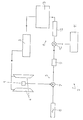
- the device for controlling a magnetic field comprises a sensor 1 in the form of a microwave oscillator with ferrous yttrium garnet resonator, the control loop 2 being mainly composed, on the one hand, of a device 5 for processing and shaping the measurement signal delivered by said sensor 1 and, on the other hand part, a device 6 for comparing the frequency of said measurement signal with that of a reference signal, and for generating a corrective signal, connected to the power supply module 3 of the magnet 4 to be checked.
- the processing device 5 consists of a harmonic mixer 7 combining the measurement signal coming from the sensor 1 with a reference signal delivered by a high stability oscillator 8, the resulting composite signal being subjected to a bandpass filter 9, the latter leaving only one of the frequency components of said composite signal.
- the device 6 for comparing and generating a corrective signal comprises a harmonic mixer 10 receiving the processed and shaped signal and combining it with a setpoint signal from a microwave synthesizer 11 programmable, and a consecutive frequency discriminator 12, connected to a generator 13 of corresponding correction signal, delivered to the power supply module 3.
- variable frequency difference between the filtered measurement signal and the setpoint signal supplied by the frequency synthesizer programmed by the user and which depends directly on the value of the magnetic field for which the magnet 4 must be controlled, is transformed into a signal with proportional variable amplitude, used by the correction signal generator 13.
- the subject of the invention is also a method for controlling the magnetic field, implementing the control device described above, essentially consisting in generating, by means of an oscillator 1 with a ferrous yttrium garnet resonator, a measurement signal whose frequency is proportional to the intensity of the magnetic field generated by the magnet to be checked, then mixing said measurement signal with a reference signal, then mixing, after filtering, the resulting composite signal with a signal instruction, by means of a harmonic mixer 10, to demodulate the signal thus obtained by performing frequency discrimination and, finally, to deliver a correction signal, function of the frequency difference between the compound signal and the signal setpoint, to the power supply module 3 of the magnet 4 generating the magnetic field to be controlled.
- the invention it is therefore possible to produce a magnetic field servo device making it possible to implement very high resolution and precision techniques of frequency measurement in the microwave domain, by means of an oscillator comprising a ferrous yttrium garnet resonator, the frequency of the signal emitted depends linearly on the surrounding magnetic field.
- the performance of the servo device according to the invention is therefore significantly higher than that of all existing systems.
Landscapes
- Engineering & Computer Science (AREA)
- Physics & Mathematics (AREA)
- Electromagnetism (AREA)
- General Physics & Mathematics (AREA)
- Radar, Positioning & Navigation (AREA)
- Automation & Control Theory (AREA)
- Control Of Motors That Do Not Use Commutators (AREA)
- Magnetic Resonance Imaging Apparatus (AREA)
Applications Claiming Priority (2)
| Application Number | Priority Date | Filing Date | Title |
|---|---|---|---|
| FR9207947 | 1992-06-24 | ||
| FR9207947A FR2693006A1 (fr) | 1992-06-24 | 1992-06-24 | Dispositif d'asservissement d'un champ magnétique et procédé mettant en Óoeuvre ledit dispositif. |
Publications (2)
| Publication Number | Publication Date |
|---|---|
| EP0576381A1 true EP0576381A1 (de) | 1993-12-29 |
| EP0576381B1 EP0576381B1 (de) | 1996-10-23 |
Family
ID=9431282
Family Applications (1)
| Application Number | Title | Priority Date | Filing Date |
|---|---|---|---|
| EP19930440050 Expired - Lifetime EP0576381B1 (de) | 1992-06-24 | 1993-06-23 | Verfahren und Vorrichtung zur Servosteuerung eines magnetischen Feldes |
Country Status (3)
| Country | Link |
|---|---|
| EP (1) | EP0576381B1 (de) |
| DE (1) | DE69305580T2 (de) |
| FR (1) | FR2693006A1 (de) |
Cited By (1)
| Publication number | Priority date | Publication date | Assignee | Title |
|---|---|---|---|---|
| CN107315445A (zh) * | 2017-07-07 | 2017-11-03 | 京东方科技集团股份有限公司 | 一种磁悬浮物体的控制方法和磁悬浮底座和磁悬浮物体 |
Citations (3)
| Publication number | Priority date | Publication date | Assignee | Title |
|---|---|---|---|---|
| FR2415387A1 (fr) * | 1978-01-18 | 1979-08-17 | Daumas Jean | Oscillateur a autoasservissement de phase |
| DE2953035A1 (de) * | 1979-01-24 | 1980-11-13 | Caspers Friedhelm | Vorrichtung zur stabilisierung von magnetfeldern |
| FR2597656A1 (fr) * | 1984-03-19 | 1987-10-23 | Enertec | Electro-aimant a champ reglable et application aux filtres a resonance gyromagnetique |
-
1992
- 1992-06-24 FR FR9207947A patent/FR2693006A1/fr active Granted
-
1993
- 1993-06-23 DE DE1993605580 patent/DE69305580T2/de not_active Expired - Fee Related
- 1993-06-23 EP EP19930440050 patent/EP0576381B1/de not_active Expired - Lifetime
Patent Citations (3)
| Publication number | Priority date | Publication date | Assignee | Title |
|---|---|---|---|---|
| FR2415387A1 (fr) * | 1978-01-18 | 1979-08-17 | Daumas Jean | Oscillateur a autoasservissement de phase |
| DE2953035A1 (de) * | 1979-01-24 | 1980-11-13 | Caspers Friedhelm | Vorrichtung zur stabilisierung von magnetfeldern |
| FR2597656A1 (fr) * | 1984-03-19 | 1987-10-23 | Enertec | Electro-aimant a champ reglable et application aux filtres a resonance gyromagnetique |
Cited By (1)
| Publication number | Priority date | Publication date | Assignee | Title |
|---|---|---|---|---|
| CN107315445A (zh) * | 2017-07-07 | 2017-11-03 | 京东方科技集团股份有限公司 | 一种磁悬浮物体的控制方法和磁悬浮底座和磁悬浮物体 |
Also Published As
| Publication number | Publication date |
|---|---|
| FR2693006A1 (fr) | 1993-12-31 |
| FR2693006B1 (de) | 1997-03-07 |
| DE69305580D1 (de) | 1996-11-28 |
| EP0576381B1 (de) | 1996-10-23 |
| DE69305580T2 (de) | 1997-05-28 |
Similar Documents
| Publication | Publication Date | Title |
|---|---|---|
| EP0333572B1 (de) | Vorrichtung zum Formatieren und Auswerten der von einem Gleichstrommotor generierten Induktionsströme, insbesondere zur Positionsregelung | |
| FR2543747A1 (fr) | Procede et dispositif de pompage optique d'une cellule de resonance magnetique nucleaire | |
| FR2787700A1 (fr) | Dispositif anti-eblouissant et procede pour commander un tel dispositif | |
| FR2473700A1 (fr) | Capteur de proximite | |
| EP0576381B1 (de) | Verfahren und Vorrichtung zur Servosteuerung eines magnetischen Feldes | |
| US6496255B2 (en) | Measurement of crystal face orientation | |
| EP0579537B1 (de) | Magnetometer mit polarisiertem Licht und gesteuertem Hochfrequenzfeld | |
| EP0642144A1 (de) | Vorrichtung zur Übertragung von elektrischen Leistungssignalen zu einem rotierenden System | |
| WO1997003488A1 (fr) | Source de lumiere a spectre large stabilise et gyroscope a fibre optique associe | |
| EP0380404B1 (de) | Regelverfahren und Schaltkreis eines Gleichstrommotors mittels der Regelspannung des Motors | |
| FR2894663A1 (fr) | Gyrolaser a etat solide active optiquement par biais alternatif | |
| EP0250292B1 (de) | Den Strom störende Sonde mit Resonanzschleife | |
| EP0562990B1 (de) | Verfahren zur Synchronisation ohne zeitliche Fluktuation eines aktiv modengekoppelten Lasers | |
| FR2552613A1 (fr) | Dispositif de chauffage par micro-ondes | |
| EP0520897B1 (de) | Steuereinrichtung für ein Kreuzspulanzeigegerät | |
| EP0699911B1 (de) | Verbesserter Drehzahlgeber sowie seine Verwendung, insbesondere bei drehenden Maschinen in Kraftwerken | |
| EP0995995B1 (de) | Messwertgeber für Drehgeschwindigkeit und Drehrichtung eines rotierenden Teils | |
| FR2505521A1 (fr) | Dispositif de commutation integre pour une commande par decoupage de phase au moyen d'un capteur a effet hall | |
| JPH06281887A (ja) | 光アイソレータ装置 | |
| FR2474689A1 (fr) | Capteur de course comportant un fil ferromagnetique de composition determinee | |
| FR2473731A1 (fr) | Dispositif de poursuite d'une cible par faisceau laser | |
| FR2496290A1 (fr) | Circuit d'asservissement numerique en fonction de la frequence | |
| CH638895A5 (fr) | Dispositif de mesure des niveaux vibratoires d'une machine tournante. | |
| FR2580442A1 (fr) | Dispositif de regulation d'un moteur electrique a courant continu et applications a un mesureur d'effort et a un dispositif d'exercice physique | |
| FR2668610A1 (fr) | Procede de reglage d'un magnetometre optique. |
Legal Events
| Date | Code | Title | Description |
|---|---|---|---|
| PUAI | Public reference made under article 153(3) epc to a published international application that has entered the european phase |
Free format text: ORIGINAL CODE: 0009012 |
|
| AK | Designated contracting states |
Kind code of ref document: A1 Designated state(s): BE CH DE FR GB LI |
|
| 17P | Request for examination filed |
Effective date: 19940315 |
|
| 17Q | First examination report despatched |
Effective date: 19940726 |
|
| GRAG | Despatch of communication of intention to grant |
Free format text: ORIGINAL CODE: EPIDOS AGRA |
|
| GRAG | Despatch of communication of intention to grant |
Free format text: ORIGINAL CODE: EPIDOS AGRA |
|
| GRAH | Despatch of communication of intention to grant a patent |
Free format text: ORIGINAL CODE: EPIDOS IGRA |
|
| GRAH | Despatch of communication of intention to grant a patent |
Free format text: ORIGINAL CODE: EPIDOS IGRA |
|
| GRAA | (expected) grant |
Free format text: ORIGINAL CODE: 0009210 |
|
| AK | Designated contracting states |
Kind code of ref document: B1 Designated state(s): BE CH DE FR GB LI |
|
| REF | Corresponds to: |
Ref document number: 69305580 Country of ref document: DE Date of ref document: 19961128 |
|
| REG | Reference to a national code |
Ref country code: CH Ref legal event code: NV Representative=s name: WERNER FENNER PATENTANWALT |
|
| GBT | Gb: translation of ep patent filed (gb section 77(6)(a)/1977) |
Effective date: 19970122 |
|
| PLBE | No opposition filed within time limit |
Free format text: ORIGINAL CODE: 0009261 |
|
| STAA | Information on the status of an ep patent application or granted ep patent |
Free format text: STATUS: NO OPPOSITION FILED WITHIN TIME LIMIT |
|
| 26N | No opposition filed | ||
| REG | Reference to a national code |
Ref country code: FR Ref legal event code: CD |
|
| REG | Reference to a national code |
Ref country code: CH Ref legal event code: PFA Free format text: SADIS BRUKER SPECTROSPIN, SOCIETE ANONYME DE DIFFUSION DE L'INSTRUMENTATION SCIENTIFIQUE BRUKER SPECTROSPIN TRANSFER- BRUKER SA Ref country code: CH Ref legal event code: NV Representative=s name: PATENTANWALTSBUERO FELDMANN AG |
|
| REG | Reference to a national code |
Ref country code: CH Ref legal event code: PK Ref country code: CH Ref legal event code: NV Representative=s name: WERNER FENNER PATENTANWALT |
|
| REG | Reference to a national code |
Ref country code: GB Ref legal event code: IF02 |
|
| REG | Reference to a national code |
Ref country code: FR Ref legal event code: CD |
|
| REG | Reference to a national code |
Ref country code: FR Ref legal event code: CD |
|
| REG | Reference to a national code |
Ref country code: CH Ref legal event code: PFA Free format text: BRUKER SA TRANSFER- BRUKER BIOSPIN SA |
|
| PGFP | Annual fee paid to national office [announced via postgrant information from national office to epo] |
Ref country code: BE Payment date: 20070622 Year of fee payment: 15 |
|
| PGFP | Annual fee paid to national office [announced via postgrant information from national office to epo] |
Ref country code: DE Payment date: 20070627 Year of fee payment: 15 |
|
| PGFP | Annual fee paid to national office [announced via postgrant information from national office to epo] |
Ref country code: GB Payment date: 20070514 Year of fee payment: 15 Ref country code: CH Payment date: 20070925 Year of fee payment: 15 |
|
| PGFP | Annual fee paid to national office [announced via postgrant information from national office to epo] |
Ref country code: FR Payment date: 20070419 Year of fee payment: 15 |
|
| BERE | Be: lapsed |
Owner name: S.A. *BRUKER BIOSPIN Effective date: 20080630 |
|
| REG | Reference to a national code |
Ref country code: CH Ref legal event code: PL |
|
| GBPC | Gb: european patent ceased through non-payment of renewal fee |
Effective date: 20080623 |
|
| PG25 | Lapsed in a contracting state [announced via postgrant information from national office to epo] |
Ref country code: BE Free format text: LAPSE BECAUSE OF NON-PAYMENT OF DUE FEES Effective date: 20080630 |
|
| REG | Reference to a national code |
Ref country code: FR Ref legal event code: ST Effective date: 20090228 |
|
| PG25 | Lapsed in a contracting state [announced via postgrant information from national office to epo] |
Ref country code: DE Free format text: LAPSE BECAUSE OF NON-PAYMENT OF DUE FEES Effective date: 20090101 |
|
| PG25 | Lapsed in a contracting state [announced via postgrant information from national office to epo] |
Ref country code: LI Free format text: LAPSE BECAUSE OF NON-PAYMENT OF DUE FEES Effective date: 20080630 Ref country code: GB Free format text: LAPSE BECAUSE OF NON-PAYMENT OF DUE FEES Effective date: 20080623 Ref country code: CH Free format text: LAPSE BECAUSE OF NON-PAYMENT OF DUE FEES Effective date: 20080630 |
|
| PG25 | Lapsed in a contracting state [announced via postgrant information from national office to epo] |
Ref country code: FR Free format text: LAPSE BECAUSE OF NON-PAYMENT OF DUE FEES Effective date: 20080630 |