EP0576381A1 - Method and device for the servo-control of a magnetic field - Google Patents
Method and device for the servo-control of a magnetic field Download PDFInfo
- Publication number
- EP0576381A1 EP0576381A1 EP93440050A EP93440050A EP0576381A1 EP 0576381 A1 EP0576381 A1 EP 0576381A1 EP 93440050 A EP93440050 A EP 93440050A EP 93440050 A EP93440050 A EP 93440050A EP 0576381 A1 EP0576381 A1 EP 0576381A1
- Authority
- EP
- European Patent Office
- Prior art keywords
- signal
- magnetic field
- magnet
- power supply
- supply module
- Prior art date
- Legal status (The legal status is an assumption and is not a legal conclusion. Google has not performed a legal analysis and makes no representation as to the accuracy of the status listed.)
- Granted
Links
Images
Classifications
-
- H—ELECTRICITY
- H03—ELECTRONIC CIRCUITRY
- H03L—AUTOMATIC CONTROL, STARTING, SYNCHRONISATION, OR STABILISATION OF GENERATORS OF ELECTRONIC OSCILLATIONS OR PULSES
- H03L7/00—Automatic control of frequency or phase; Synchronisation
- H03L7/02—Automatic control of frequency or phase; Synchronisation using a frequency discriminator comprising a passive frequency-determining element
- H03L7/04—Automatic control of frequency or phase; Synchronisation using a frequency discriminator comprising a passive frequency-determining element wherein the frequency-determining element comprises distributed inductance and capacitance
-
- G—PHYSICS
- G05—CONTROLLING; REGULATING
- G05F—SYSTEMS FOR REGULATING ELECTRIC OR MAGNETIC VARIABLES
- G05F7/00—Regulating magnetic variables
Definitions
- the present invention relates to the field of command and control of parameters, in particular of the intensity, of a magnetic field and relates to a device for controlling a magnetic field, as well as a method implementing said device.
- Hall effect probes elements with variable resistance as a function of the surrounding magnetic field and gaussmeters with a rotating coil are known.
- each of these known measurement and control devices and methods has one or more drawbacks as to their performance or their possibilities of implementation, namely, a relatively low resolution or precision of measurement and control. , or a limited operating range, or the need for complex equipment, resulting, in particular, in long and tedious adjustments.
- the problem posed in the present invention therefore consists in designing a device for controlling a magnetic field having, on the one hand, a very good resolution, as well as a very good measurement and servo precision, of on the other hand, a wide operating range and, finally, a simple structure allowing rapid adjustment, more particularly of the set value of the magnetic field to be controlled.
- the present invention relates to a device for controlling a magnetic field, comprising a sensor placed in the magnetic field to be controlled and a control loop controlling the power supply module of the magnet generating said magnetic field, characterized in that the sensor is in the form of a garnet resonator microwave oscillator ferrous yttrium, the control loop being mainly composed, on the one hand, of a device for processing and shaping the measurement signal delivered by said sensor and, on the other hand, of a device for comparing the frequency of said measurement signal with that of a reference signal and of generation of a corrective signal, connected to the power supply module of the magnet to be checked.
- the invention also relates to a method for controlling a magnetic field, using the device described above and characterized in that it essentially consists in generating, by means of a resonator oscillator at ferrous yttrium garnet, a measurement signal whose frequency is proportional to the intensity of the magnetic field generated by the magnet to be checked, then mixing said measurement signal with a reference signal, then mixing, after filtering, the resulting composite signal with a setpoint signal, by means of a harmonic mixer, to demodulate the signal thus obtained by performing frequency discrimination and, finally, to deliver a correction signal, a function of the frequency difference between the compound signal and the setpoint signal, to the power supply module of the magnet generating the magnetic field to be controlled.
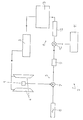
- the device for controlling a magnetic field comprises a sensor 1 in the form of a microwave oscillator with ferrous yttrium garnet resonator, the control loop 2 being mainly composed, on the one hand, of a device 5 for processing and shaping the measurement signal delivered by said sensor 1 and, on the other hand part, a device 6 for comparing the frequency of said measurement signal with that of a reference signal, and for generating a corrective signal, connected to the power supply module 3 of the magnet 4 to be checked.
- the processing device 5 consists of a harmonic mixer 7 combining the measurement signal coming from the sensor 1 with a reference signal delivered by a high stability oscillator 8, the resulting composite signal being subjected to a bandpass filter 9, the latter leaving only one of the frequency components of said composite signal.
- the device 6 for comparing and generating a corrective signal comprises a harmonic mixer 10 receiving the processed and shaped signal and combining it with a setpoint signal from a microwave synthesizer 11 programmable, and a consecutive frequency discriminator 12, connected to a generator 13 of corresponding correction signal, delivered to the power supply module 3.
- variable frequency difference between the filtered measurement signal and the setpoint signal supplied by the frequency synthesizer programmed by the user and which depends directly on the value of the magnetic field for which the magnet 4 must be controlled, is transformed into a signal with proportional variable amplitude, used by the correction signal generator 13.
- the subject of the invention is also a method for controlling the magnetic field, implementing the control device described above, essentially consisting in generating, by means of an oscillator 1 with a ferrous yttrium garnet resonator, a measurement signal whose frequency is proportional to the intensity of the magnetic field generated by the magnet to be checked, then mixing said measurement signal with a reference signal, then mixing, after filtering, the resulting composite signal with a signal instruction, by means of a harmonic mixer 10, to demodulate the signal thus obtained by performing frequency discrimination and, finally, to deliver a correction signal, function of the frequency difference between the compound signal and the signal setpoint, to the power supply module 3 of the magnet 4 generating the magnetic field to be controlled.
- the invention it is therefore possible to produce a magnetic field servo device making it possible to implement very high resolution and precision techniques of frequency measurement in the microwave domain, by means of an oscillator comprising a ferrous yttrium garnet resonator, the frequency of the signal emitted depends linearly on the surrounding magnetic field.
- the performance of the servo device according to the invention is therefore significantly higher than that of all existing systems.
Abstract
Description
La présente invention concerne le domaine de la commande et du contrôle des paramètres, notamment de l'intensité, d'un champ magnétique et a pour objet un dispositif d'asservissement d'un champ magnétique, ainsi qu'un procédé mettant en oeuvre ledit dispositif.The present invention relates to the field of command and control of parameters, in particular of the intensity, of a magnetic field and relates to a device for controlling a magnetic field, as well as a method implementing said device.
Il existe actuellement déjà différents dispositifs pour la mesure et l'asservissement d'un champ magnétique.There are currently already various devices for measuring and controlling a magnetic field.
Ainsi, on connaît notamment, en tant que capteurs de mesure, faisant partie de dispositifs d'asservissement, les sondes à effet Hall, les éléments à résistance variable en fonction du champ magnétique environnant et les gaussmètres à bobine tournante.Thus, in particular, as measurement sensors, forming part of servo-control devices, Hall effect probes, elements with variable resistance as a function of the surrounding magnetic field and gaussmeters with a rotating coil are known.
En outre, il est également connu de réaliser un asservissement d'un champ magnétique basé sur un signal d'absorption de résonance paramagnétique électronique ou de résonance magnétique nucléaire.In addition, it is also known to produce a control of a magnetic field based on an absorption signal of electronic paramagnetic resonance or nuclear magnetic resonance.
Néanmoins, chacun de ces dispositifs et procédés de mesure et d'asservissements connus présente un ou plusieurs inconvénients quant à leurs performances ou à leurs possibilités de mise en oeuvre, à savoir, soit une résolution ou une précision de mesure et d'asservissement relativement faible, soit une plage de fonctionnement limitée, ou encore la nécessité de disposer d'un appareillage complexe, entraînant, notamment, des réglages longs et fastidieux.However, each of these known measurement and control devices and methods has one or more drawbacks as to their performance or their possibilities of implementation, namely, a relatively low resolution or precision of measurement and control. , or a limited operating range, or the need for complex equipment, resulting, in particular, in long and tedious adjustments.
Le problème posé à la présente invention consiste par conséquent à concevoir un dispositif d'asservissement d'un champ magnétique présentant, d'une part, une très bonne résolution, ainsi qu'une très bonne précision de mesure et d'asservissement, d'autre part, une large plage de fonctionnement et, enfin, une structure simple permettant un réglage rapide, plus particulièrement de la valeur de consigne du champ magnétique à asservir.The problem posed in the present invention therefore consists in designing a device for controlling a magnetic field having, on the one hand, a very good resolution, as well as a very good measurement and servo precision, of on the other hand, a wide operating range and, finally, a simple structure allowing rapid adjustment, more particularly of the set value of the magnetic field to be controlled.
A cet effet, la présente invention a pour objet un dispositif d'asservissement d'un champ magnétique, comportant un capteur disposé dans le champ magnétique à asservir et une boucle d'asservissement contrôlant le module d'alimentation de l'aimant générateur dudit champ magnétique, caractérisé en ce que le capteur se présente sous la forme d'un oscillateur hyperfréquence à résonateur au grenat d'yttrium ferreux, la boucle d'asservissement étant principalement composée, d'une part, d'un dispositif de traitement et de mise en forme du signal de mesure délivré par ledit capteur et, d'autre part, d'un dispositif de comparaison de la fréquence dudit signal de mesure avec celle d'un signal de référence et de génération d'un signal correcteur, relié au module d'alimentation de l'aimant à contrôler.To this end, the present invention relates to a device for controlling a magnetic field, comprising a sensor placed in the magnetic field to be controlled and a control loop controlling the power supply module of the magnet generating said magnetic field, characterized in that the sensor is in the form of a garnet resonator microwave oscillator ferrous yttrium, the control loop being mainly composed, on the one hand, of a device for processing and shaping the measurement signal delivered by said sensor and, on the other hand, of a device for comparing the frequency of said measurement signal with that of a reference signal and of generation of a corrective signal, connected to the power supply module of the magnet to be checked.
L'invention a également pour objet un procédé d'asservissement d'un champ magnétique, mettant en oeuvre le dispositif décrit ci-dessus et caractérisé en ce qu'il consiste essentiellement à générer, par l'intermédiaire d'un oscillateur à résonateur au grenat d'yttrium ferreux, un signal de mesure dont la fréquence est proportionnelle à l'intensité du champ magnétique généré par l'aimant à contrôler, à mélanger ensuite ledit signal de mesure avec un signal de référence, puis à mélanger, après filtrage, le signal composé résultant avec un signal de consigne, au moyen d'un mélangeur harmonique, à démoduler le signal ainsi obtenu en effectuant une discrimination de fréquence et, enfin, à délivrer un signal de correction, fonction de l'écart de fréquence entre le signal composé et le signal de consigne, au module d'alimentation de l'aimant générateur du champ magnétique à asservir.The invention also relates to a method for controlling a magnetic field, using the device described above and characterized in that it essentially consists in generating, by means of a resonator oscillator at ferrous yttrium garnet, a measurement signal whose frequency is proportional to the intensity of the magnetic field generated by the magnet to be checked, then mixing said measurement signal with a reference signal, then mixing, after filtering, the resulting composite signal with a setpoint signal, by means of a harmonic mixer, to demodulate the signal thus obtained by performing frequency discrimination and, finally, to deliver a correction signal, a function of the frequency difference between the compound signal and the setpoint signal, to the power supply module of the magnet generating the magnetic field to be controlled.
L'invention sera mieux comprise grâce à la description ci-après, qui se rapporte à un mode de réalisation préféré, donné à titre d'exemple non limitatif, et expliqué avec référence au dessin annexé, dont la figure unique est un schéma synoptique du dispositif d'asservissement selon l'invention.The invention will be better understood thanks to the description below, which relates to a preferred embodiment, given by way of nonlimiting example, and explained with reference to the appended drawing, the single figure of which is a block diagram of the servo device according to the invention.
Conformément à l'invention, et comme le montre la figure du dessin annexé, le dispositif d'asservissement d'un champ magnétique comporte un capteur 1 sous la forme d'un oscillateur hyperfréquence à résonateur au grenat d'yttrium ferreux, la boucle d'asservissement 2 étant principalement composée, d'une part, d'un dispositif 5 de traitement et de mise en forme du signal de mesure délivré par ledit capteur 1 et, d'autre part, d'un dispositif 6 de comparaison de la fréquence dudit signal de mesure avec celle d'un signal de référence, et de génération d'un signal correcteur, relié au module d'alimentation 3 de l'aimant 4 à contrôler.According to the invention, and as shown in the figure of the accompanying drawing, the device for controlling a magnetic field comprises a sensor 1 in the form of a microwave oscillator with ferrous yttrium garnet resonator, the
Selon une première caractéristique de l'invention, le dispositif 5 de traitement est constitué par un mélangeur harmonique 7 combinant le signal de mesure issu du capteur 1 avec un signal de référence délivré par un oscillateur 8 à grande stabilité, le signal composé résultant étant soumis à un filtre passe-bande 9, ce dernier ne laissant subsister qu'une des composantes fréquentielles dudit signal composé.According to a first characteristic of the invention, the processing device 5 consists of a
Comme le montre également la figure du dessin annexé, le dispositif 6 de comparaison et de génération d'un signal correcteur comporte un mélangeur harmonique 10 recevant le signal traité et mis en forme et le combinant avec un signal de consigne issu d'un synthétiseur hyperfréquence 11 programmable, et un discriminateur de fréquence 12 consécutif, relié à un générateur 13 de signal de correction correspondant, délivré au module d'alimentation 3.As also shown in the figure of the appended drawing, the device 6 for comparing and generating a corrective signal comprises a
Ainsi, la différence de fréquences variable entre le signal de mesure filtré et le signal de consigne, fourni par le synthétiseur de fréquence programmé par l'utilisateur et qui dépend directement de la valeur du champ magnétique pour laquelle l'aimant 4 doit être asservi, est transformée en un signal à amplitude variable proportionnelle, exploité par le générateur de signal de correction 13.Thus, the variable frequency difference between the filtered measurement signal and the setpoint signal, supplied by the frequency synthesizer programmed by the user and which depends directly on the value of the magnetic field for which the
La constitution et le mode de fonctionnement des différents dispositifs électroniques 1, 3 et 5 à 13 décrits ci-dessus, connus de l'homme de métier, ne seront pas décrits de manière plus précise dans la présente demande.The constitution and the mode of operation of the various electronic devices 1, 3 and 5 to 13 described above, known to those skilled in the art, will not be described in more detail in the present application.
L'invention a également pour objet un procédé d'asservissement de champ magnétique, mettant en oeuvre le dispositif d'asservissement décrit précédemment, consistant essentiellement à générer par l'intermédiaire d'un oscillateur 1 à résonateur au grenat d'yttrium ferreux, un signal de mesure dont la fréquence est proportionnelle à l'intensité du champ magnétique généré par l'aimant à contrôler, à mélanger ensuite ledit signal de mesure avec un signal de référence, puis à mélanger, après filtrage, le signal composé résultant avec un signal de consigne, au moyen d'un mélangeur harmonique 10, à démoduler le signal ainsi obtenu en effectuant une discrimination de fréquence et, enfin, à délivrer un signal de correction, fonction de l'écart de fréquence entre le signal composé et le signal de consigne, au module d'alimentation 3 de l'aimant 4 générateur du champ magnétique à asservir.The subject of the invention is also a method for controlling the magnetic field, implementing the control device described above, essentially consisting in generating, by means of an oscillator 1 with a ferrous yttrium garnet resonator, a measurement signal whose frequency is proportional to the intensity of the magnetic field generated by the magnet to be checked, then mixing said measurement signal with a reference signal, then mixing, after filtering, the resulting composite signal with a signal instruction, by means of a
Grâce à l'invention, il est donc possible de réaliser un dispositif d'asservissement de champ magnétique permettant de mettre en oeuvre les techniques à très hautes résolution et précision de la mesure de fréquence dans le domaine des hyperfréquences, par l'intermédiaire d'un oscillatcur comportant un résonateur à grenat d'yttrium ferreux, dont la fréquence du signal émis dépend linéairement du champ magnétique environnant.Thanks to the invention, it is therefore possible to produce a magnetic field servo device making it possible to implement very high resolution and precision techniques of frequency measurement in the microwave domain, by means of an oscillator comprising a ferrous yttrium garnet resonator, the frequency of the signal emitted depends linearly on the surrounding magnetic field.
Les performances du dispositif d'asservissement conforme à l'invention sont de ce fait nettement supérieures à celles de l'ensemble des systèmes existant.The performance of the servo device according to the invention is therefore significantly higher than that of all existing systems.
En effet, il permet d'atteindre une précision de mesure et d'asservissement du champ magnétique de l'ordre de 10⁻⁶ avec une résolution d'environ 10⁻⁷ T et une plage opérationnelle s'étendant de 0,1 T à 1,2 T.Indeed, it makes it possible to achieve measurement and servo precision of the magnetic field of the order of 10⁻⁶ with a resolution of around 10 d'environ T and an operational range extending from 0.1 T to 1.2 T.
Bien entendu, l'invention n'est pas limitée au mode de réalisation décrit et représenté au dessin annexé. Des modifications restent possibles, notamment du point de vue de la constitution des divers éléments, ou par substitution d'équivalents techniques, sans sortir pour autant du domaine de protection de l'invention.Of course, the invention is not limited to the embodiment described and shown in the accompanying drawing. Modifications remain possible, in particular from the point of view of the constitution of the various elements, or by substitution of technical equivalents, without thereby departing from the scope of protection of the invention.
Claims (4)
Applications Claiming Priority (2)
| Application Number | Priority Date | Filing Date | Title |
|---|---|---|---|
| FR9207947 | 1992-06-24 | ||
| FR9207947A FR2693006A1 (en) | 1992-06-24 | 1992-06-24 | Device for controlling a magnetic field and method implementing said device. |
Publications (2)
| Publication Number | Publication Date |
|---|---|
| EP0576381A1 true EP0576381A1 (en) | 1993-12-29 |
| EP0576381B1 EP0576381B1 (en) | 1996-10-23 |
Family
ID=9431282
Family Applications (1)
| Application Number | Title | Priority Date | Filing Date |
|---|---|---|---|
| EP19930440050 Expired - Lifetime EP0576381B1 (en) | 1992-06-24 | 1993-06-23 | Method and device for the servo-control of a magnetic field |
Country Status (3)
| Country | Link |
|---|---|
| EP (1) | EP0576381B1 (en) |
| DE (1) | DE69305580T2 (en) |
| FR (1) | FR2693006A1 (en) |
Cited By (1)
| Publication number | Priority date | Publication date | Assignee | Title |
|---|---|---|---|---|
| CN107315445A (en) * | 2017-07-07 | 2017-11-03 | 京东方科技集团股份有限公司 | The control method and magnetic suspended basement and magnetically levitated object of a kind of magnetically levitated object |
Citations (3)
| Publication number | Priority date | Publication date | Assignee | Title |
|---|---|---|---|---|
| FR2415387A1 (en) * | 1978-01-18 | 1979-08-17 | Daumas Jean | Stabilised frequency phase loop oscillator - uses analogue or digital delay line to produce phase difference between two signals |
| DE2953035A1 (en) * | 1979-01-24 | 1980-11-13 | Caspers Friedhelm | Magnetic field stabilising circuit - employs YIG probe operating in conjunction with FM microwave oscillator to produce compensating excitation |
| FR2597656A1 (en) * | 1984-03-19 | 1987-10-23 | Enertec | Adjustable-field electromagnet and application to gyromagnetic-resonance filters |
-
1992
- 1992-06-24 FR FR9207947A patent/FR2693006A1/en active Granted
-
1993
- 1993-06-23 EP EP19930440050 patent/EP0576381B1/en not_active Expired - Lifetime
- 1993-06-23 DE DE1993605580 patent/DE69305580T2/en not_active Expired - Fee Related
Patent Citations (3)
| Publication number | Priority date | Publication date | Assignee | Title |
|---|---|---|---|---|
| FR2415387A1 (en) * | 1978-01-18 | 1979-08-17 | Daumas Jean | Stabilised frequency phase loop oscillator - uses analogue or digital delay line to produce phase difference between two signals |
| DE2953035A1 (en) * | 1979-01-24 | 1980-11-13 | Caspers Friedhelm | Magnetic field stabilising circuit - employs YIG probe operating in conjunction with FM microwave oscillator to produce compensating excitation |
| FR2597656A1 (en) * | 1984-03-19 | 1987-10-23 | Enertec | Adjustable-field electromagnet and application to gyromagnetic-resonance filters |
Cited By (1)
| Publication number | Priority date | Publication date | Assignee | Title |
|---|---|---|---|---|
| CN107315445A (en) * | 2017-07-07 | 2017-11-03 | 京东方科技集团股份有限公司 | The control method and magnetic suspended basement and magnetically levitated object of a kind of magnetically levitated object |
Also Published As
| Publication number | Publication date |
|---|---|
| DE69305580T2 (en) | 1997-05-28 |
| FR2693006B1 (en) | 1997-03-07 |
| EP0576381B1 (en) | 1996-10-23 |
| FR2693006A1 (en) | 1993-12-31 |
| DE69305580D1 (en) | 1996-11-28 |
Similar Documents
| Publication | Publication Date | Title |
|---|---|---|
| EP0333572B1 (en) | Formatting and utilisation device for induced waves generated by a dc motor, especially for position control | |
| FR2543747A1 (en) | METHOD AND APPARATUS FOR OPTICALLY PUMPING A NUCLEAR MAGNETIC RESONANCE CELL | |
| CH635948A5 (en) | POSITION CONTROL DEVICE. | |
| CH629689A5 (en) | Ultrasonic oscillator and ultrasonic machine tool using this oscillator | |
| EP0576381B1 (en) | Method and device for the servo-control of a magnetic field | |
| US6496255B2 (en) | Measurement of crystal face orientation | |
| EP0579537B1 (en) | Magnetometer with polarized light and servo-controlled radio frequency field | |
| FR2713347A1 (en) | Light polarization magnetometer coupled to radio frequency field. | |
| EP0642144A1 (en) | Device for the transmission of electric power signals to a rotating system | |
| WO1997003488A1 (en) | Stabilised broad-spectrum light source and related fibre-optic gyroscope | |
| EP0353153A1 (en) | Magnetic oscillation and guiding device for charged particles for the amplification of an electromagnetic emission | |
| FR2493628A1 (en) | DEVICE FOR STOPPING THE ROTATION OF A MOTOR | |
| EP0380404B1 (en) | Method and circuit for the speed control of a DC motor by the motor control voltage | |
| FR2894663A1 (en) | OPTICALLY ACTIVE SOLID STATE GYROLASER THROUGH ALTERNATIVE BIAIS | |
| EP0250292B1 (en) | Interference current probe comprising a resonant loop | |
| EP0562990B1 (en) | Method of synchronisation of an active mode locked laser without temporal fluctuations | |
| EP0520897B1 (en) | Controller for a crossed-coil meter | |
| EP0995995B1 (en) | Transducer for measurement of speed and direction of rotation of a body | |
| FR2505521A1 (en) | INTEGRATED SWITCHING DEVICE FOR PHASE CUTTING CONTROL USING A HALL EFFECT SENSOR | |
| JPH0669583A (en) | Wavelength stabilizing equipment | |
| JPH06281887A (en) | Optical isolator | |
| FR2474689A1 (en) | Distance transducer assembly - has ferromagnetic wire moving w.r.t. coils and supplied with excitation current with different coil field strengths | |
| FR2473731A1 (en) | Laser beam tracking system - uses synchronous detector comparing phase of received beam and oscillator output to provide control signals operating motor to move mirror | |
| FR2496290A1 (en) | DIGITAL RELAY CIRCUIT BASED ON FREQUENCY | |
| CH638895A5 (en) | DEVICE FOR MEASURING THE VIBRATORY LEVELS OF A ROTATING MACHINE. |
Legal Events
| Date | Code | Title | Description |
|---|---|---|---|
| PUAI | Public reference made under article 153(3) epc to a published international application that has entered the european phase |
Free format text: ORIGINAL CODE: 0009012 |
|
| AK | Designated contracting states |
Kind code of ref document: A1 Designated state(s): BE CH DE FR GB LI |
|
| 17P | Request for examination filed |
Effective date: 19940315 |
|
| 17Q | First examination report despatched |
Effective date: 19940726 |
|
| GRAG | Despatch of communication of intention to grant |
Free format text: ORIGINAL CODE: EPIDOS AGRA |
|
| GRAG | Despatch of communication of intention to grant |
Free format text: ORIGINAL CODE: EPIDOS AGRA |
|
| GRAH | Despatch of communication of intention to grant a patent |
Free format text: ORIGINAL CODE: EPIDOS IGRA |
|
| GRAH | Despatch of communication of intention to grant a patent |
Free format text: ORIGINAL CODE: EPIDOS IGRA |
|
| GRAA | (expected) grant |
Free format text: ORIGINAL CODE: 0009210 |
|
| AK | Designated contracting states |
Kind code of ref document: B1 Designated state(s): BE CH DE FR GB LI |
|
| REF | Corresponds to: |
Ref document number: 69305580 Country of ref document: DE Date of ref document: 19961128 |
|
| REG | Reference to a national code |
Ref country code: CH Ref legal event code: NV Representative=s name: WERNER FENNER PATENTANWALT |
|
| GBT | Gb: translation of ep patent filed (gb section 77(6)(a)/1977) |
Effective date: 19970122 |
|
| PLBE | No opposition filed within time limit |
Free format text: ORIGINAL CODE: 0009261 |
|
| STAA | Information on the status of an ep patent application or granted ep patent |
Free format text: STATUS: NO OPPOSITION FILED WITHIN TIME LIMIT |
|
| 26N | No opposition filed | ||
| REG | Reference to a national code |
Ref country code: FR Ref legal event code: CD |
|
| REG | Reference to a national code |
Ref country code: CH Ref legal event code: PFA Free format text: SADIS BRUKER SPECTROSPIN, SOCIETE ANONYME DE DIFFUSION DE L'INSTRUMENTATION SCIENTIFIQUE BRUKER SPECTROSPIN TRANSFER- BRUKER SA Ref country code: CH Ref legal event code: NV Representative=s name: PATENTANWALTSBUERO FELDMANN AG |
|
| REG | Reference to a national code |
Ref country code: CH Ref legal event code: PK Ref country code: CH Ref legal event code: NV Representative=s name: WERNER FENNER PATENTANWALT |
|
| REG | Reference to a national code |
Ref country code: GB Ref legal event code: IF02 |
|
| REG | Reference to a national code |
Ref country code: FR Ref legal event code: CD |
|
| REG | Reference to a national code |
Ref country code: FR Ref legal event code: CD |
|
| REG | Reference to a national code |
Ref country code: CH Ref legal event code: PFA Free format text: BRUKER SA TRANSFER- BRUKER BIOSPIN SA |
|
| PGFP | Annual fee paid to national office [announced via postgrant information from national office to epo] |
Ref country code: BE Payment date: 20070622 Year of fee payment: 15 |
|
| PGFP | Annual fee paid to national office [announced via postgrant information from national office to epo] |
Ref country code: DE Payment date: 20070627 Year of fee payment: 15 |
|
| PGFP | Annual fee paid to national office [announced via postgrant information from national office to epo] |
Ref country code: GB Payment date: 20070514 Year of fee payment: 15 Ref country code: CH Payment date: 20070925 Year of fee payment: 15 |
|
| PGFP | Annual fee paid to national office [announced via postgrant information from national office to epo] |
Ref country code: FR Payment date: 20070419 Year of fee payment: 15 |
|
| BERE | Be: lapsed |
Owner name: S.A. *BRUKER BIOSPIN Effective date: 20080630 |
|
| REG | Reference to a national code |
Ref country code: CH Ref legal event code: PL |
|
| GBPC | Gb: european patent ceased through non-payment of renewal fee |
Effective date: 20080623 |
|
| PG25 | Lapsed in a contracting state [announced via postgrant information from national office to epo] |
Ref country code: BE Free format text: LAPSE BECAUSE OF NON-PAYMENT OF DUE FEES Effective date: 20080630 |
|
| REG | Reference to a national code |
Ref country code: FR Ref legal event code: ST Effective date: 20090228 |
|
| PG25 | Lapsed in a contracting state [announced via postgrant information from national office to epo] |
Ref country code: DE Free format text: LAPSE BECAUSE OF NON-PAYMENT OF DUE FEES Effective date: 20090101 |
|
| PG25 | Lapsed in a contracting state [announced via postgrant information from national office to epo] |
Ref country code: LI Free format text: LAPSE BECAUSE OF NON-PAYMENT OF DUE FEES Effective date: 20080630 Ref country code: GB Free format text: LAPSE BECAUSE OF NON-PAYMENT OF DUE FEES Effective date: 20080623 Ref country code: CH Free format text: LAPSE BECAUSE OF NON-PAYMENT OF DUE FEES Effective date: 20080630 |
|
| PG25 | Lapsed in a contracting state [announced via postgrant information from national office to epo] |
Ref country code: FR Free format text: LAPSE BECAUSE OF NON-PAYMENT OF DUE FEES Effective date: 20080630 |